Focus This Week
This week is focused on Mechanical Design and Machine Design. The goals were to work as a team to design and build a machine (incorporating mechanism, actuation, and automation), construct the mechanical components, and write control software. I designed the Go-Kart Steering Linkage Mechanism and developed an automated Steering Durability Test Rig Machine to physically cycle the steering assembly and evaluate mechanical wear.
Group Assignment — Durability Testing Machine
Our group project was to build a machine that automates mechanical reliability tests on fabricated kart parts. The full machine layout, assembly schematics, and group contribution files are documented on the Fablab Dilijan Group Machine Page.
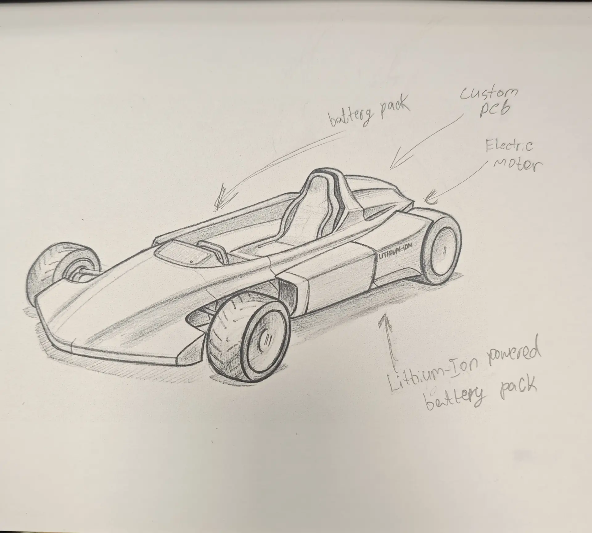
Machine Mechanism & Actuation
- Mechanical Structure: Constructed from 20x20mm T-slot aluminum profiles, linear guide rails, and 3D printed carriages.
- Actuation System: A NEMA 17 stepper motor coupled to an 8mm lead screw. This translates rotational force into linear motion.
- Automation Logic: An Arduino Uno with a CNC Shield V3 driving an A4988 stepper driver. The controller runs a cycling code that pushes the tie-rod back and forth, simulating 10,000 steering cycles.
Individual Assignment — Linkage Design and Integration
My primary contribution to the group machine was the mechanical design and assembly of the Go-Kart steering linkages. I designed a system using dual tie-rods connected to a central steering column arm (Pitman arm) and outer steering knuckles.
Ackermann Steering Geometry
To ensure the wheels roll smoothly during turns without slipping sideways, I calculated the geometry based on **Ackermann steering principles**:
* The inside wheel must turn at a sharper angle than the outside wheel because it follows a smaller turning radius.
* I angled the steering arms inwards so that lines drawn through the steering knuckle pivot pins and tie-rod ends intersect at the center of the kart's rear axle.
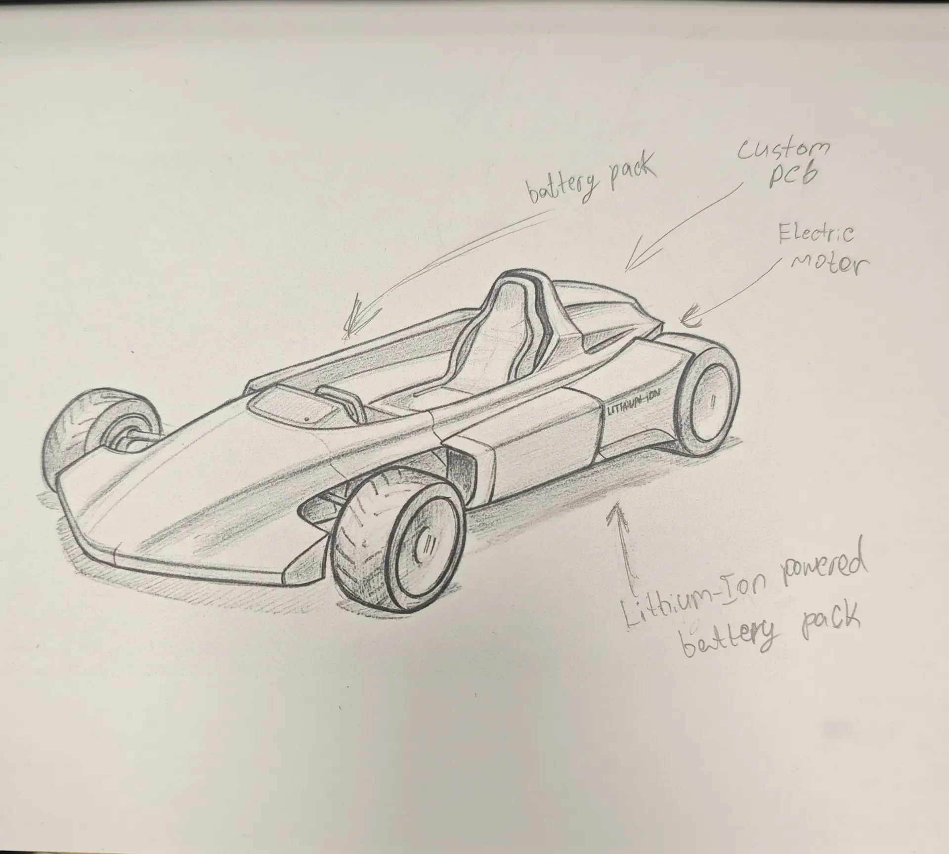
Automation Control Code
I wrote the stepper cycling software that runs on the test machine, using the AccelStepper library to ensure smooth acceleration profiles:
// Machine Stepper Controller - AccelStepper Durability Test
#include <AccelStepper.h>

// Define pin connections for CNC Shield (X-Axis)
const int STEP_PIN = 2;
const int DIR_PIN = 5;
const int ENABLE_PIN = 8;

// Define stepper parameters
AccelStepper stepper(AccelStepper::DRIVER, STEP_PIN, DIR_PIN);

const long TARGET_POSITION = 4000; // Total steps per sweep (approx 50mm travel)
int cyclesCount = 0;

void setup() {
  Serial.begin(115200);
  pinMode(ENABLE_PIN, OUTPUT);
  digitalWrite(ENABLE_PIN, LOW); // Enable stepper drivers

  stepper.setMaxSpeed(1000.0);
  stepper.setAcceleration(500.0);
  stepper.moveTo(TARGET_POSITION);
}

void loop() {
  // Cycle back and forth
  if (stepper.distanceToGo() == 0) {
    long nextPos = (stepper.currentPosition() == 0) ? TARGET_POSITION : 0;
    stepper.moveTo(nextPos);
    cyclesCount++;

    Serial.print("Cycle Completed. Total: ");
    Serial.println(cyclesCount / 2);
  }

  stepper.run();
}
Original Design Files
Download the 3D assembly CAD and code files for the steering mechanism:
| File Name | Format | Description | Download Link |
|---|---|---|---|
| steering_assembly.f3d | F3D (Fusion 360) | 3D assembly model containing steering column, knuckles, and tie-rods. | 📥 Download F3D |
| steering_test_rig.ino | Arduino Code (.ino) | Control software utilizing AccelStepper to cycle the machine slider. | 📥 Download INO |
Have you answered these questions?
- Documented the machine building process to the group page?
Yes. The complete machine construction log is detailed on the group page. - Documented your individual contribution to this project on your own website?
Yes. My individual contribution—designing the steering knuckle linkages and mounting steering gear mechanisms—is documented in the Individual Contribution section. - Linked to the group page from your individual page as well as from group page to your individual pages?
Yes. The group page and cross-member profiles are linked at the top in the Group Work section. - Shown how your team planned, allocated tasks and executed the project (Group page)?
Yes. Task delegation, Gantt charting, and planning are documented on the group page. - Described problems and how the team solved them (Group page)?
Yes. Mechanical alignment errors and backlash calibration are documented on the group page. - Listed possible improvements for this project (Group page)?
Yes. Improvements (such as adding needle bearings to steering hubs) are listed. - Included your design files (Group page)?
Yes. Mechanical CAD models and gear profiles are downloadable from the group repository. - You need to present your machine globally and/or include a 1 min video (1920x1080 HTML5 MP4) + slide (1920x1080 PNG) (Group page)?
Yes. The 1-minute video showing the steering rig automation is linked on the group page.
Week 12 — Summary
This week focused on mechanisms, kinematic assembly, and automated testing. Here is a summary of the accomplishments:
Ackermann Modeled
Designed steering knuckle geometries in CAD matching Ackermann intersection lines to prevent slip angles.
Actuator Assembled
Built a linear lead-screw slider mechanism powered by stepper motors to cycle steering components.
Loops Automated
Programmed the stepper controller with velocity ramping limits in C++ to automate load fatigue tests.
Group Integration
Collaborated with the lab team to assemble structures, align guide shafts, and compile the group test report.