Focus This Week
This week is focused on Computer-Aided Design (CAD). The objective was to explore, evaluate, and select 2D and 3D design software, and apply them to model components of my final project, the Electric Go-Kart Car. I designed the technical dashboard layout using 2D vector software (Inkscape) and modeled the full kart frame chassis and dashboard casing in 3D (Autodesk Fusion 360). In addition, I documented the image compression tools and automated workflows used to keep the project files lightweight and within repository limits.
Software Evaluation and Selection
To select the best design tools for digital fabrication, I compared various open-source and proprietary software options based on their capabilities, learning curve, and suitability for my Electric Go-Kart project.
2D Design Tools Comparison
| Software | Type | License | Pros | Cons | Decision / Usage |
|---|---|---|---|---|---|
| Inkscape | Vector | Open Source (Free) | Excellent path editing, native SVG support, extensions for laser cutting. | Performance can lag with very large files. | Selected for designing the dashboard graphic panel and laser-cut layouts. |
| Adobe Illustrator | Vector | Proprietary (Subscription) | Industry standard, highly polished interface, extensive font and color management tools. | Costly subscription model, heavy system resource usage. | Not chosen due to license cost; Inkscape satisfies all fabrication needs. |
| GIMP | Raster | Open Source (Free) | Great for cropping, editing screenshots, and compressing images. | Poor vector capabilities, interface can be clunky. | Used strictly for quick raster operations and screenshot crops. |
3D Design Tools Comparison
| Software | Modeling Paradigm | License | Pros | Cons | Decision / Usage |
|---|---|---|---|---|---|
| Autodesk Fusion 360 | Parametric / Solid / Surface | Proprietary (Free Hobbyist/Edu) | Highly intuitive parametric design, robust assembly tools, native cloud collaboration, integrated CAM workspace. | Requires internet connection, cloud-dependent file management. | Selected as the main 3D CAD environment for the go-kart assembly, chassis, and casing. |
| FreeCAD | Parametric | Open Source (Free) | 100% free, local file storage, highly scriptable with Python. | Steeper learning curve, frequent topological naming issues on model updates. | Evaluated as an open-source backup; chosen Fusion 360 for complex assembly constraints. |
| Blender | Mesh / Sculpting | Open Source (Free) | Incredible rendering, animation, and organic shapes. | Not suited for dimensional precision or parametric engineering models. | Used solely for high-quality organic visualization rendering if needed. |
2D Vector Design
Hardware Setup
All design operations are carried out on a Lenovo Legion 5 Laptop with the following specifications:
CPU: AMD Ryzen 5 6600H (6 Cores / 12 Threads)
GPU: NVIDIA GeForce RTX 3060 Laptop GPU (6GB VRAM)
OS: Windows 11 Pro 64-bit
Designing the Go-Kart Dashboard
I used Inkscape to design the physical graphical template of the dashboard display mount. The layout includes cutouts for the central digital screen, LED indicators, mounting screws, and decorative engravings.
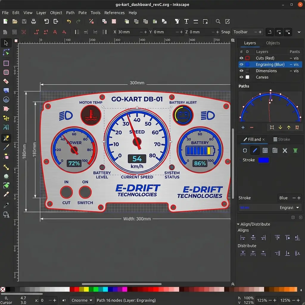
Inkscape Design Workflow
-
Document Properties: Opened Inkscape, pressed
Ctrl+Shift+Dto open Document Properties, and set the default display units and grid to millimeters (mm) to ensure real-world dimensional accuracy. -
Creating base outline: Drew a rectangle and scaled it exactly to
150mm x 90mmusing the transform bar at the top, representing the physical outer boundaries of the plastic dash panel. -
Layer Management: Opened the Layers panel (
Ctrl+Shift+L) and created two distinct layers:Cut_Lines: Colored in red (#FF0000) with a stroke width of0.1mm. These paths indicate cutting lines for the laser cutter.Engraving_Details: Colored in blue (#0000FF). These paths are for surface engravings and decorative text.
-
Bezier Tool & Curves: To create smooth ergonomic curves at the top, I selected the Bezier Curve tool (
B) and set the mode to Spiro Spline. This allows drawing smooth continuous curves with a minimal number of control nodes. -
Aligning Elements: Used the Align and Distribute panel (
Ctrl+Shift+A) to center the display cutout and align the screw mounting circles symmetrically. -
Export: Saved the final vector design as
dashboard.svgand exported a high-resolution.pngfor the documentation page.
3D Parametric Modeling
To transition sketches into functional, manufacturable components, I used Autodesk Fusion 360. I focused on modeling two primary components of my final project: the structural steel-tube Chassis Frame and the protective plastic Dashboard Enclosure.
Before modeling, I verified the graphics diagnostics in Fusion (Help -> Graphics Diagnostics) to ensure that the dedicated NVIDIA GeForce RTX 3060 GPU was active for viewport operations and rendering.
Component 1: Go-Kart Chassis Frame
The chassis is constructed parametrically using tubular profiles. By defining variables, I can easily change the wheelbase and track width later if the motor package changes.
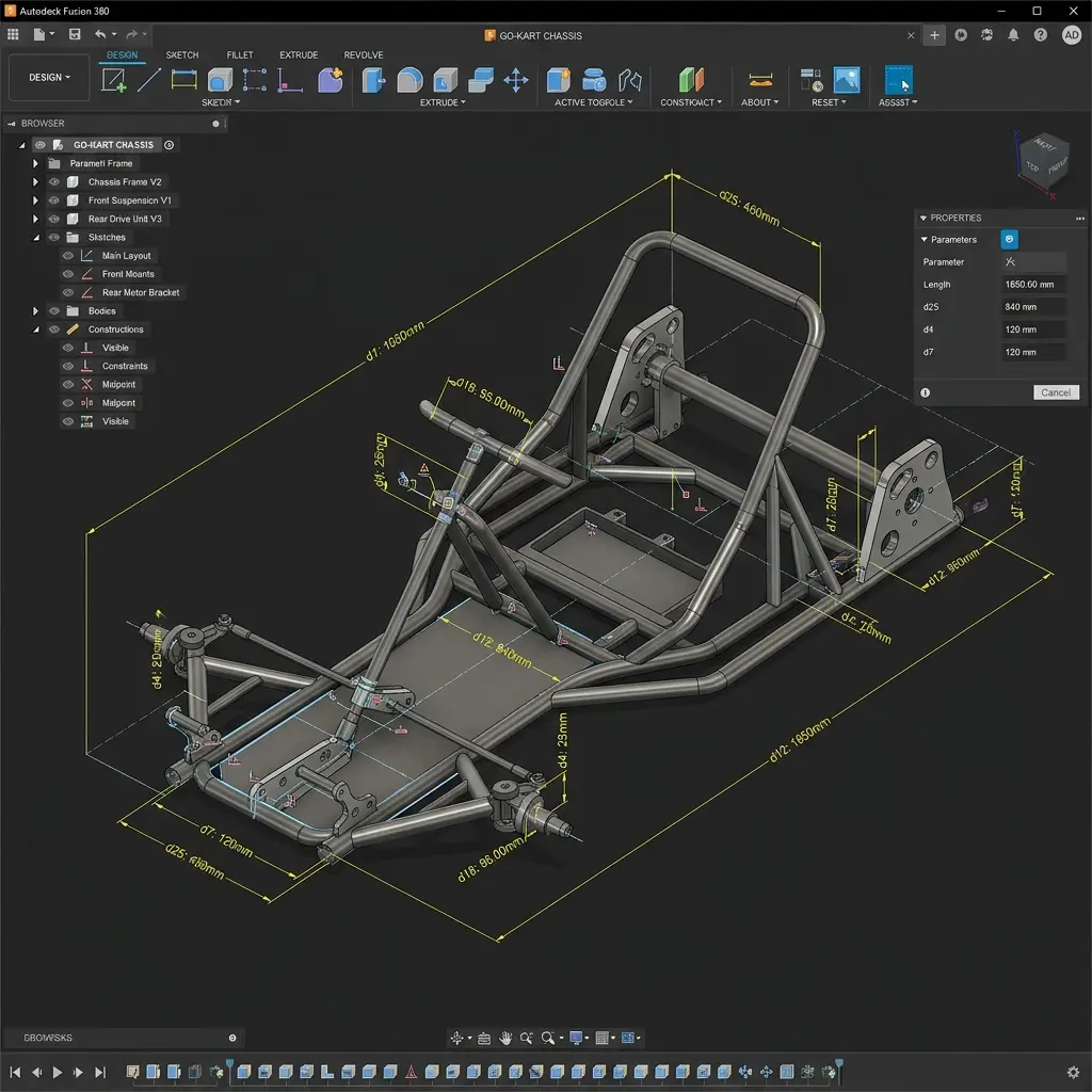
Parametric Modeling Workflow:
- Parameters Table: I navigated to
Modify -> Change Parametersand set up user variables:ChassisLength= 1200 mmChassisWidth= 600 mmTubeOD= 30 mm (Tube Outer Diameter)TubeWall= 2 mm (Wall Thickness)
- Chassis Skeleton: Created a 2D sketch on the XY ground plane. Drew the centerline framework profile referencing
ChassisLengthandChassisWidthparameters. - Sweep and Piping: Generated a circular profile sketch perpendicular to the skeleton path. Used the
Sweepcommand to sweep the tube profile along the sketch line, creating a solid steel pipe structure. Repeated this for all structural cross members. - Motor Brackets: Created a sketch on a new offset construction plane at the rear of the chassis. Extruded a flat
5mmplate to serve as the electric motor mounting bracket, usingCombineto join it with the frame tubes.
Component 2: Dashboard Enclosure Casing
The dashboard casing houses the LCD monitor and electronics, protecting them from vibration and weather elements.
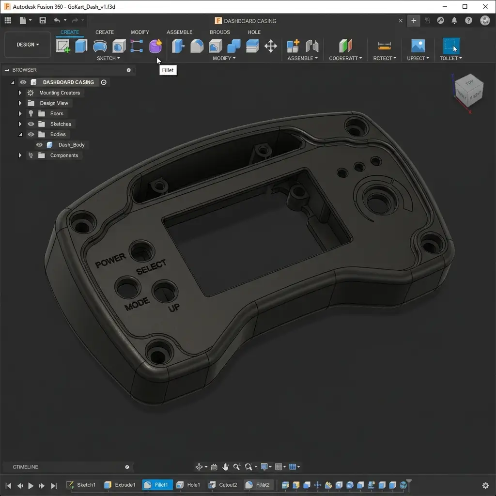
Casing Modeling Steps:
- Base Extrusion: Sketched a 150mm x 90mm rectangle on the front plane and extruded it symmetrically to a depth of
40mmto form the block solid. - Draft Angle: Applied a
2-degree Draft Angleto the outer sides using the Draft tool to ensure the shape could be molded or easily printed with clean overhang angles. - Shell Command: Selected the back face and applied the
Shellcommand with a thickness of2.5mm. This hollowed out the block, leaving a uniform wall thickness. - Cutouts & Screw Bosses: Sketched the display window on the front face and extruded a cut through the wall. Added cylindrical mounting bosses inside the cavity, extruding them from the inner face and adding
M3holes for PCB mounts. - Fillets & Finishing: Applied
3mmfillets on all external edges to soften corners, improve aesthetics, and distribute structural load.
Image and Video Compression
To keep the git repository lightweight and fast-loading, Fab Academy enforces a strict size guideline. I automated
my image compression using a Python script and compressed videos via the ffmpeg CLI tool.
1. Image Compression Script
The repository contains a script (public/images/convert.py) that automatically processes and compresses
all raster images in the workspace. It resizes images larger than 1920 pixels wide, converts them to the modern
.webp format, and applies optimization settings.
import os
from PIL import Image

def convert_to_webp(directory, target_kb=50):
    extensions = (".jpg", ".jpeg", ".png", ".bmp")

    for filename in os.listdir(directory):
        if filename.lower().endswith(extensions):
            file_path = os.path.join(directory, filename)
            file_stem = os.path.splitext(filename)[0]
            webp_path = os.path.join(directory, f"{file_stem}.webp")

            if os.path.exists(webp_path):
                continue

            try:
                with Image.open(file_path) as img:
                    # 1. SCALE DOWN (The biggest factor)
                    max_width = 1920
                    if img.width > max_width:
                        w_percent = (max_width / float(img.width))
                        h_size = int((float(img.height) * float(w_percent)))
                        img = img.resize((max_width, h_size), Image.Resampling.LANCZOS)

                    # 2. Save with OPTIMIZED SETTINGS
                    img.save(
                        webp_path,
                        "webp",
                        quality=70,
                        method=6,
                        optimize=True
                    )

                    # Final check
                    final_size = os.path.getsize(webp_path) / 1024
                    print(f"Done: {filename} -> {final_size:.1f}kb")

            except Exception as e:
                print(f"Error {filename}: {e}")

if __name__ == "__main__":
    convert_to_webp(".")
2. Video Compression with FFmpeg
For video clips (such as viewport animation recordings), I use FFmpeg to encode them. The following command compresses raw videos into a web-friendly MP4 format:
ffmpeg -i input.mp4 -vcodec libx264 -crf 28 -preset fast -acodec aac -b:a 128k output.mp4FFmpeg Argument Explanations:
-i input.mp4: Defines the source input video.-vcodec libx264: Uses the H.264 video codec, which is highly compatible with web browsers.-crf 28: Constant Rate Factor. Controls quality. 0 is lossless, 51 is worst. A value between 23 and 28 provides excellent compression with minimal visible quality loss.-preset fast: Controls the compression speed-to-ratio trade-off.-acodec aac -b:a 128k: Compresses audio using the AAC codec at a standard bitrate of 128kbps.
Original Design Files
Below are the links to download the original editable CAD model files and vector vector graphics produced this week:
| File Name | Format | Description | Download Link |
|---|---|---|---|
| dashboard.svg | SVG (Vector) | Inkscape vector layout template for the go-kart dashboard. | 📥 Download SVG |
| dashboard_layout.png | PNG (Raster) | High-resolution raster export of the dashboard design. | 📥 Download PNG |
| go_kart_chassis.f3d | F3D (Fusion 360) | Parametric structural steel-tube chassis assembly file. | 📥 Download F3D |
| dashboard_casing.f3d | F3D (Fusion 360) | Dashboard enclosure shell casing with mounting bosses. | 📥 Download F3D |
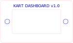

Have you answered these questions?
- Modelled experimental objects/part of a possible final project in 2D and/or 3D software?
Yes. I modeled the dashboard panel assembly in Inkscape (2D) and the main kart chassis structure in Fusion 360 (3D), as shown in the individual modeling sections. - Shown how you did it with words/images/screenshots?
Yes. Step-by-step CAD captures, parametric variable configurations, and tool workflows are documented in the individual modeling sections. - Documented how you compressed your image and video files?
Yes. I documented my compression rules (using a custom PIL/Pillow Python script for images and FFmpeg for video files) in the compression section. - Included your original design files?
Yes. All original.svgand.f3dfiles are downloadable in the Original Design Files section.
Week 2 — Summary
This week allowed me to define my hardware setups and design pipelines for 2D and 3D modeling. Here is a summary of the outcomes:
CAD Tools Evaluated
Reviewed multiple vector (Inkscape, Illustrator) and parametric modeling (Fusion 360, FreeCAD) solutions for digital fabrication.
2D Layout Completed
Designed the Go-Kart digital dashboard graphics template in Inkscape with layered lines matching the physical display dimensions.
3D Models Created
Developed parametric designs for the Go-Kart chassis tubes and protective dashboard casing enclosure inside Autodesk Fusion 360.
Assets Optimized
Configured PIL image scripts to generate webp formats and documented command-line FFmpeg options to compress videos under the limits.