Group Assignment
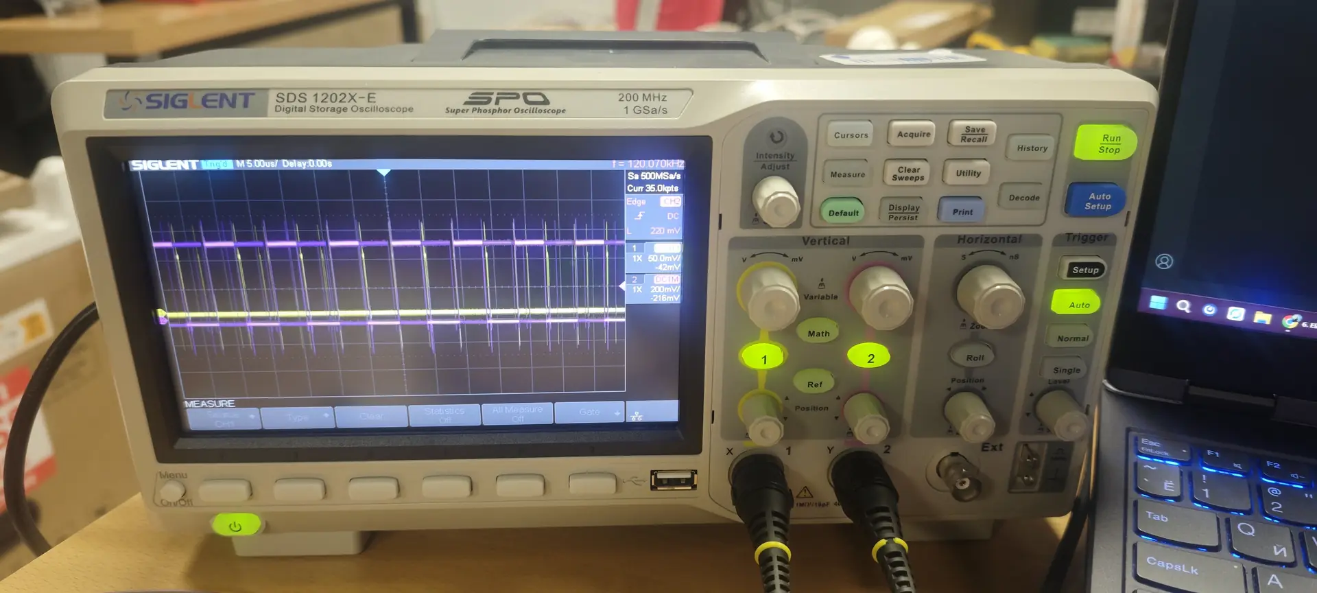
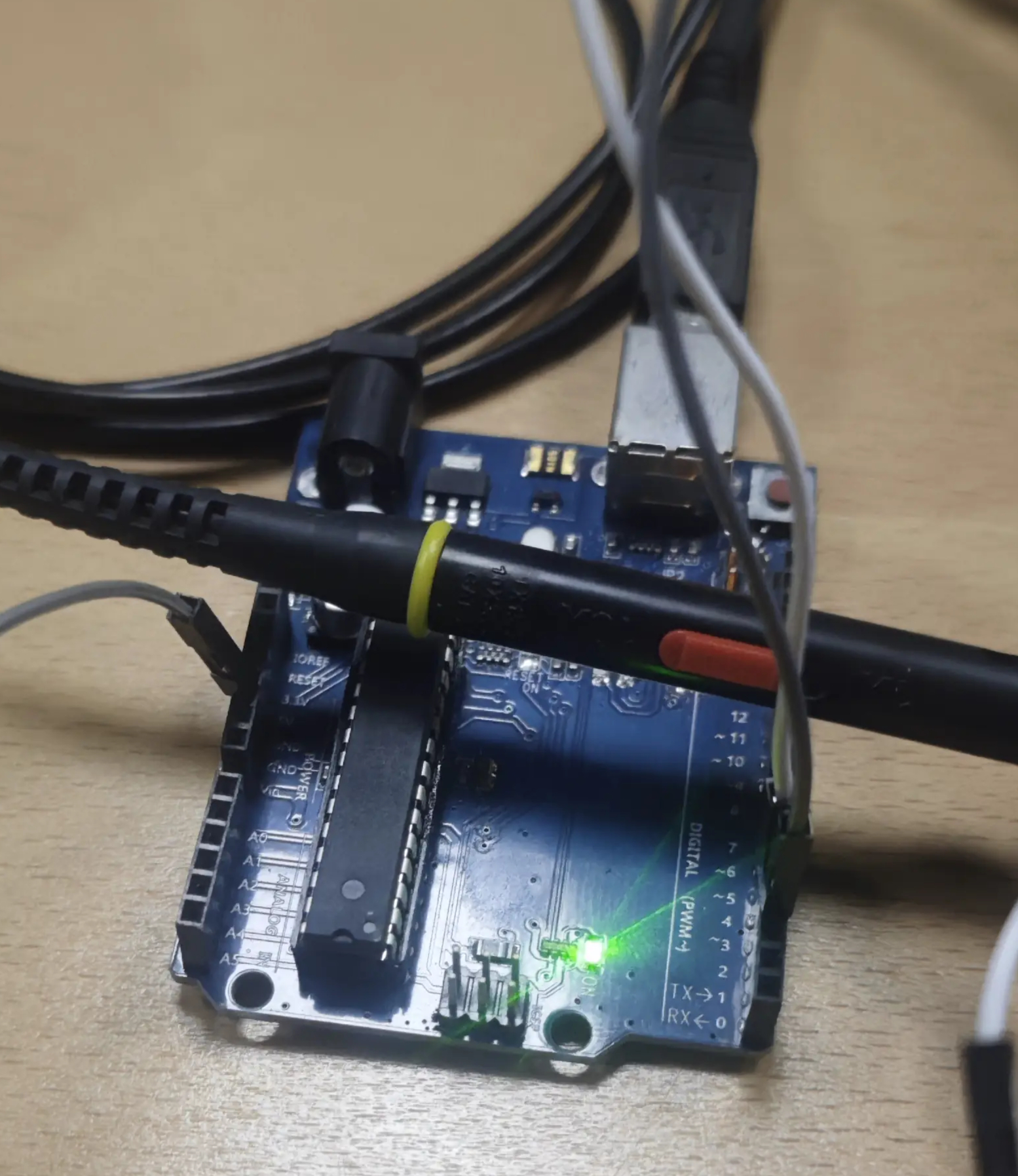
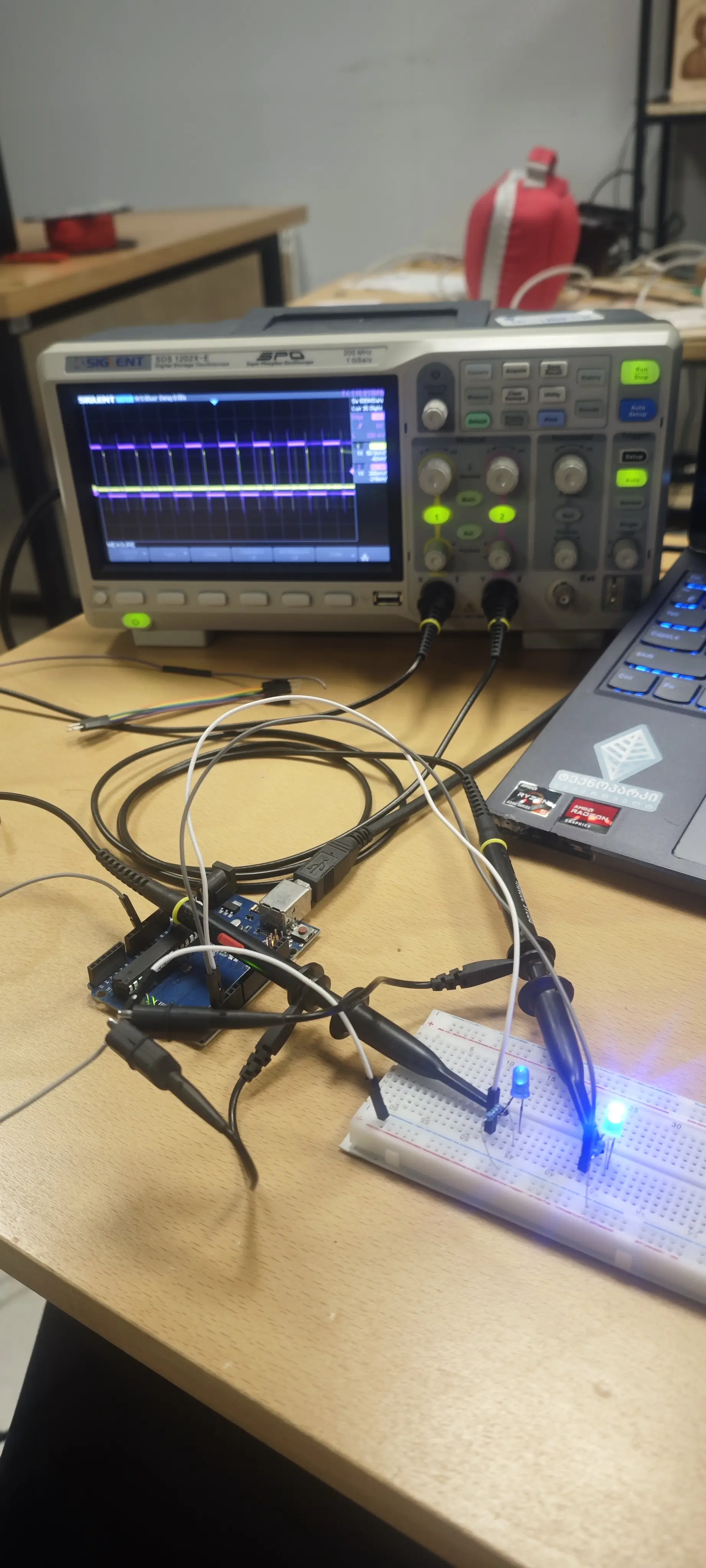
For this week group assignment we should use the test equipment in your lab to observe the operation of a microcontroller circuit board. The complete group testing report is available on the Fablab Dilijan Group Assignment Page. I'm using Siglent SDS 1202x-e digital oscilloscope for testing arduino uno board two led digitalwrite to digitalwriteFast comparison.
Siglent SDS 1202x-e Specifications:
- Bandwidth: 200 MHz
- Channels: 2 Analog
- Sample Rate: 1 GSa/s (Max)
- Memory Depth: 14 Mpts
- Waveform Capture Rate: 100,000 wfm/s (Normal mode)
- Serial Decoding: Free standard support for I2C, SPI, UART, CAN, and LIN.
- Display: 7-inch color TFT-LCD with 256-level intensity grading.
and used this code to compare digitalwrite and digitalwriteFast.
#include "digitalWriteFast.h"
void setup() {
// put your setup code here, to run once:
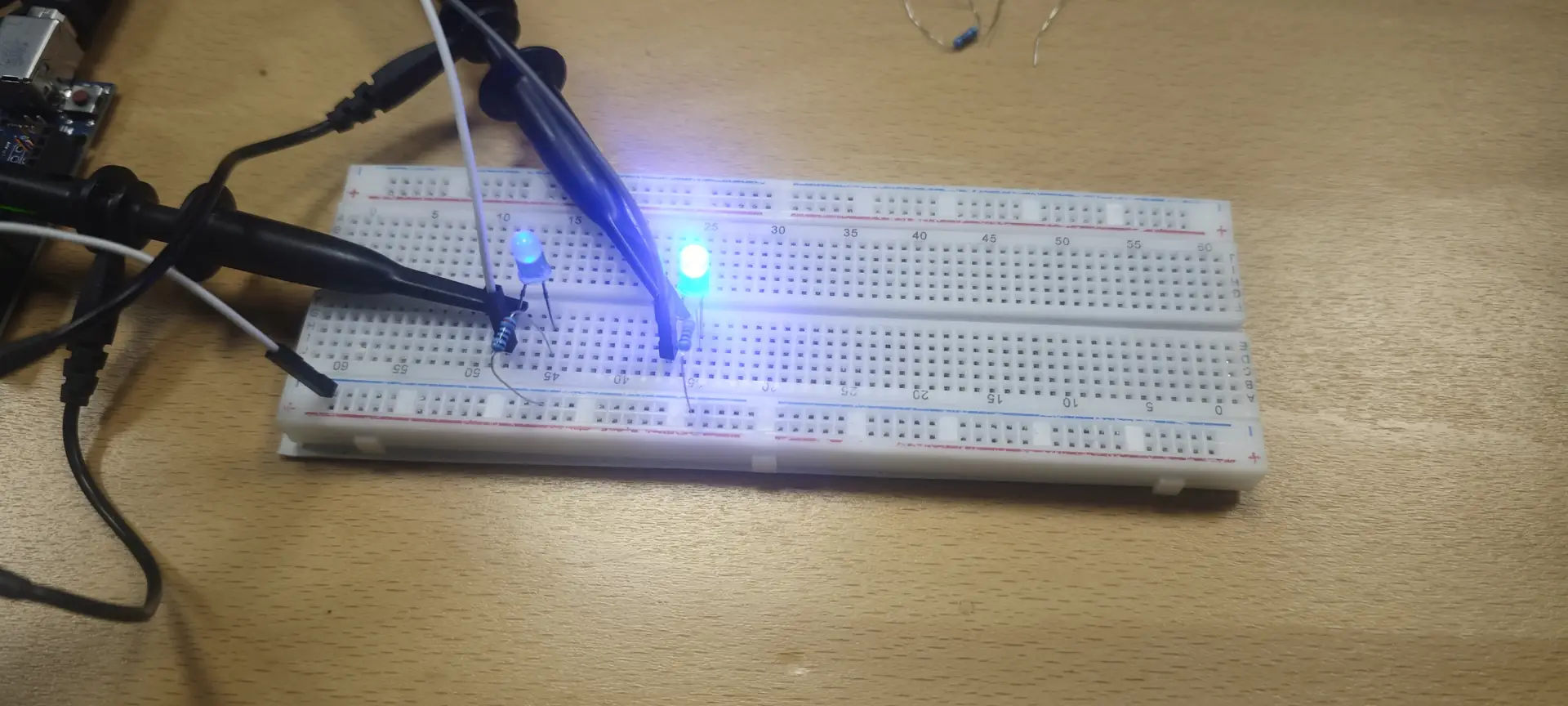
pinMode(3,OUTPUT); // led 1 pin
pinMode(4,OUTPUT); // led 2 pin
}
void loop() {
// Test Digitalwrite on led 1
digitalWrite(3, HIGH);
digitalWrite(3, LOW);
// Test DigitalWriteFast on led 2
digitalWriteFast(4,HIGH);
digitalWriteFast(4,LOW);
}
Oscilloscope Setup:
- Grounding: Connect the probe’s ground clip to the Arduino GND.
- Coupling: Use DC Coupling.
- Horizontal Scale (Timebase): Start at 5us for standard digitalWrite and dial down to 100ns for the fast version.
- Trigger: Set the trigger to Rising Edge and adjust the level to about 1.5V.
Test Results:
| Device | DigitalWrite Speed | DigitalWriteFast Speed | Speed Factor |
|---|---|---|---|
| Arduino Uno | ~6000 ns | ~125 ns | ~48x faster |
| ESP32 | ~500 ns | ~50 ns | ~10x faster |
Individual Assignment
The goal this week was to design a custom development board from scratch. The board must include a microcontroller and peripherals to allow for interaction (input/output) and communication (serial/programming).
I chose KiCad 9.0 as my EDA (Electronic Design Automation) tool, because i had a little experience with Easyeda and wanted to try something new.
Before designing, I integrated the Fab Academy 2026 library to ensure all parts used are available in our lab's inventory.
-
Symbols: Preferences > Manage Symbol Libraries -> Added fab.kicad_sym. -
Footprints: Preferences > Manage Footprint Libraries -> Added fab.pretty.
I designed a board based on the Seeed Studio XIAO ESP32C3 (or your preferred MCU from the inventory). Components Used:
- Microcontroller: Seeed Studio XIAO ESP32C3.
- Input: 1x Push Button (OMRON B3F-1000).
- Output: 1x LED (1206 SMD) with a 330 ohm current-limiting resistor.
- Power: $10\mu F$ Decoupling Capacitor to stabilize the voltage.
- Connectors: 1x6 Pin Header for external communication/FTDI.
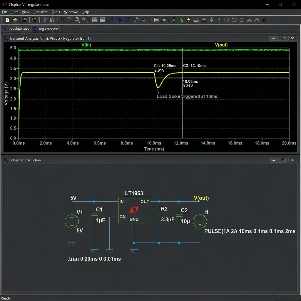
To verify the circuit before fabrication, I simulated the LED trigger logic.
I also exported the netlist to LTspice to perform a more granular stress test on the power regulation, simulating the voltage drop when the ESP32 switches from Sleep to Active mode.
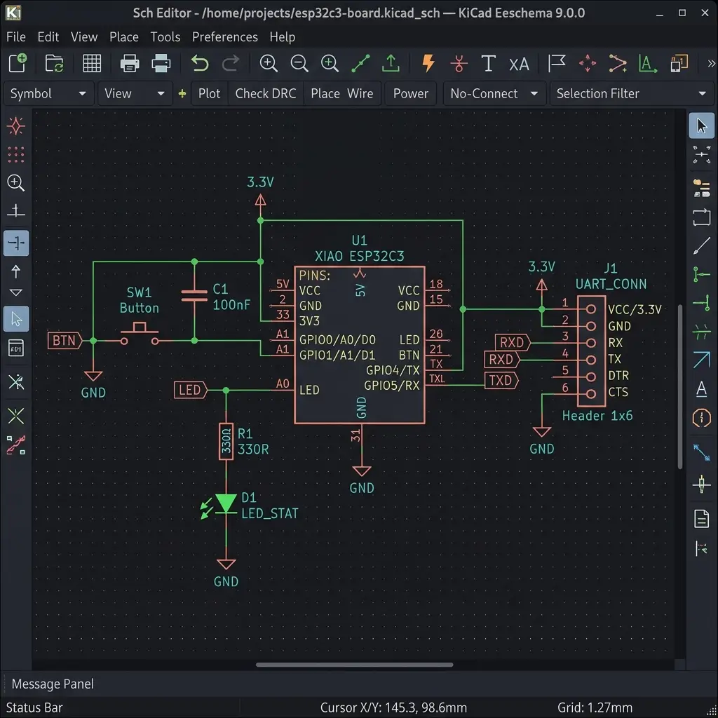
Schematic Design in KiCad
I connected the XIAO pins to peripherals: GPIO2 is mapped to the output LED, GPIO3 to the input push button (with an internal pull-up resistor enabled in software), and the UART TX/RX pins are routed to the 1x6 header for serial debugging and firmware flashing.
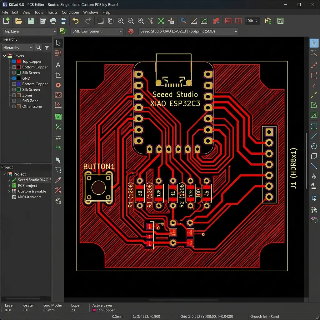
PCB Layout & Routing
- Assigning Footprints: I matched schematic symbols to hand-solderable 1206 SMD footprints from the Fab library.
- Routing Traces: I used a
0.4mmtrace width to ensure traces can be milled reliably on our CNC router without lifting. Power traces (VCC and GND) were routed with0.6mmwidth to support higher current spikes. - Design Rule Check (DRC): Configured minimum clearance to
0.4mm(based on our 1/64" PCB milling bit size) and ran the DRC. No errors or disconnected nets were found.
Original Design Files
Download the KiCad project files and schematic exports below:
| File Name | Format | Description | Download Link |
|---|---|---|---|
| dashboard_mcu.kicad_sch | KiCad Schematic (.kicad_sch) | Schematic capture file for the ESP32C3 dashboard board. | 📥 Download SCH |
| dashboard_mcu.kicad_pcb | KiCad PCB (.kicad_pcb) | PCB layout and copper routing file. | 📥 Download PCB |
| power_transient.asc | LTspice Schematic (.asc) | Simulation model for power regulator transient load spikes. | 📥 Download ASC |
Have you answered these questions?
- Linked to the group assignment page?
Yes. Linked to the Siglent oscilloscope test page in the Group Assignment section. - Documented what you have learned in electronics design?
Yes. Schematic signal routing, pull-up configurations, trace layout rules for CNC mechanical isolation (0.4mm traces), and ground fill design are detailed in the individual section. - Checked your board can be fabricated?
Yes. Run Design Rule Check (DRC) in KiCad 9.0 using a minimum trace clearance of 0.4mm matching our 1/64" PCB mill bit, as detailed in the PCB Layout section. - Explained problems and how you fixed them?
Yes. Described checking schematic errors, resolving crossing traces by rerouting, and verifying power stability using LTspice transient current load simulations. - Included original design files (Eagle, KiCad, etc.)?
Yes. Download links for.kicad_sch,.kicad_pcb, and LTspice.ascmodels are in the Original Design Files section. - Included a ‘hero shot’?
Yes. Top-level schematic captures and routed 2D layout planes are displayed.
Week 6 — Summary
This week focused on EDA schematics, routing constraints, and testing. Here is a summary of the accomplishments:
Oscilloscope Profiling
Used digital oscilloscopes to profile digitalWrite timing, showing a 48x performance gain with static direct register writes.
Schematic Captured
Designed a custom XIAO ESP32C3 dashboard development board schematic using the Fab Academy library.
PCB routed and DRC Checked
Routed all copper traces with 0.4mm clearances and passed all Design Rule Checks for CNC mechanical isolation.
Circuit Simulated
Performed SPICE transient simulations in LTspice to verify power supply decoupling stability under microcontroller wakeup cycles.