Focus This Week
This week is focused on Computer-Controlled Cutting. The learning outcomes involve understanding safety protocols and operational workflows for laser cutters and vinyl plotters, calibrating the kerf for press-fit joints, and creating a parametric design that assembles without adhesives. I completed the safety training, characterized our lab's CO2 laser cutter (Bodor BCL-1309XUF), designed and fabricated a modular cardboard construction kit, and cut a safety warning sticker for the laser cutter using the Mimaki CG-130FXII vinyl plotter.
Group Assignment — Safety and Characterization
The group assignment for this week was to perform safety training, characterize the laser cutter's focus, power, speed, joint clearance, and kerf. The complete group page can be viewed on the Fablab Dilijan Group Assignment Page.
1) Safety Training
Before operating the laser cutter, we follow strict safety rules in our lab to prevent fire hazards, toxic fumes, and equipment damage.
1. Never Leave the Laser Unattended
The laser cutter must never be left unattended while operating.
Even if the cutting job takes a long time, we stay in the same room and continuously monitor the process.
Laser cutting plywood or cardboard can ignite unexpectedly. Immediate reaction is critical to prevent fire.
2. Extra Care with Plywood and Cardboard
When cutting plywood or cardboard, we take additional precautions because:
- These materials are highly flammable
- Glue layers in plywood can ignite
- Cardboard can burn quickly if power/speed settings are incorrect
We carefully monitor flame formation and are ready to stop the machine immediately if necessary.
3. Industrial Ventilation System
Our lab uses an extra industrial ventilation module.
- The exhaust duct extends above the building roof
- This prevents smoke from spreading inside the building
- It protects other workers and nearby animals from harmful fumes
Proper ventilation is essential because laser cutting produces smoke and fine particles.
4. Water Cooling / Chiller System Check
Before every cutting session, we:
- Check the water cooling (chiller) system
- Confirm water circulation is working
- Ensure the temperature is within a safe operating range
Laser tubes can overheat and be permanently damaged if cooling fails.
5. Additional Safety Measures
- Never cut PVC or unknown plastics (to avoid toxic chlorine gas)
- Keep a fire extinguisher accessible
- Clean the cutting bed before operation
- Turn on air assist during cutting
2) Laser Cutter Characterization
To understand the capabilities of our cutting machinery, we characterized the Bodor BCL-1309XUF laser engraving and cutting machine. Below is the documentation of the hardware setup and parameter matrix.
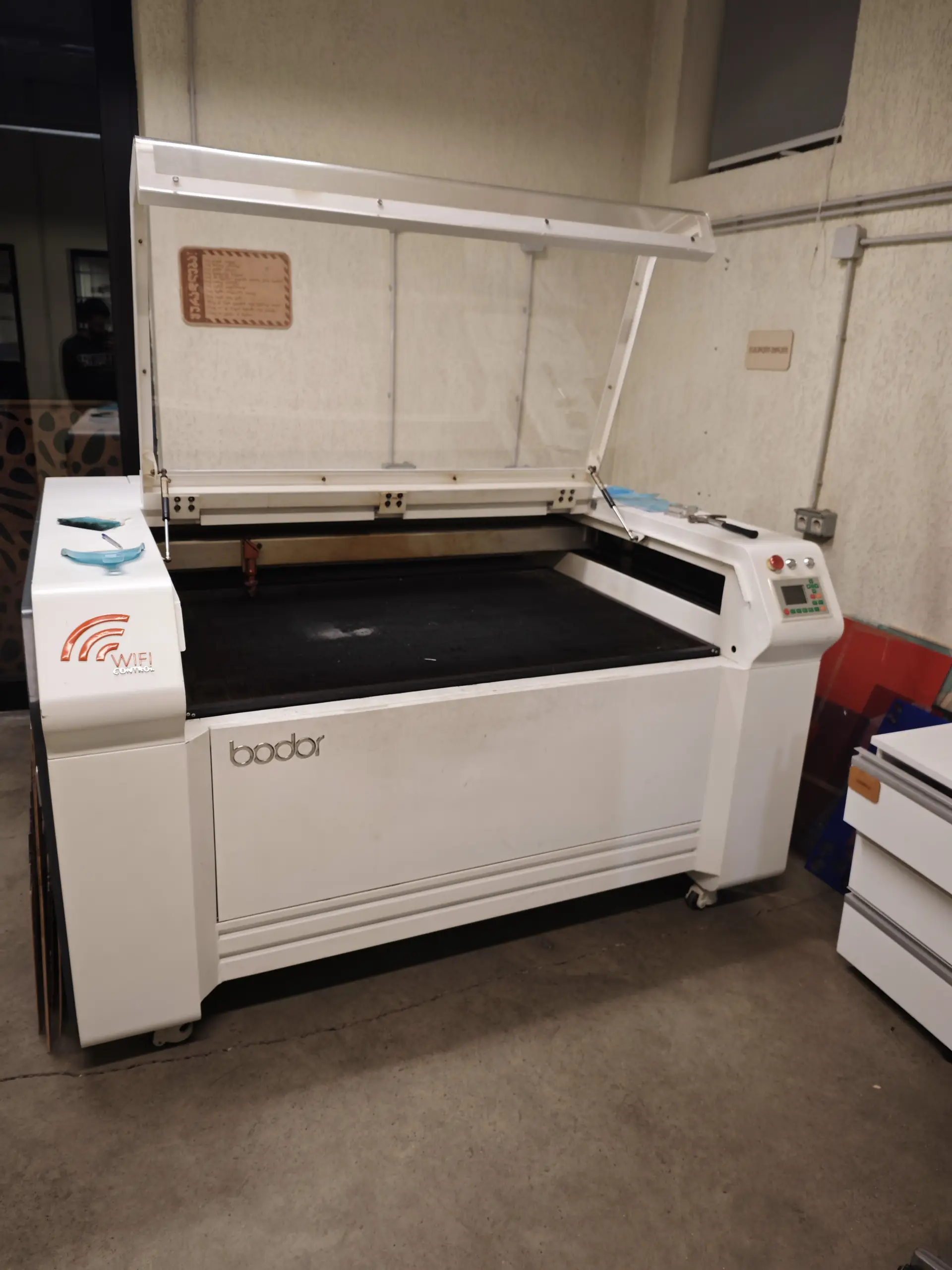
Bodor BCL-1309XUF Laser Cutter
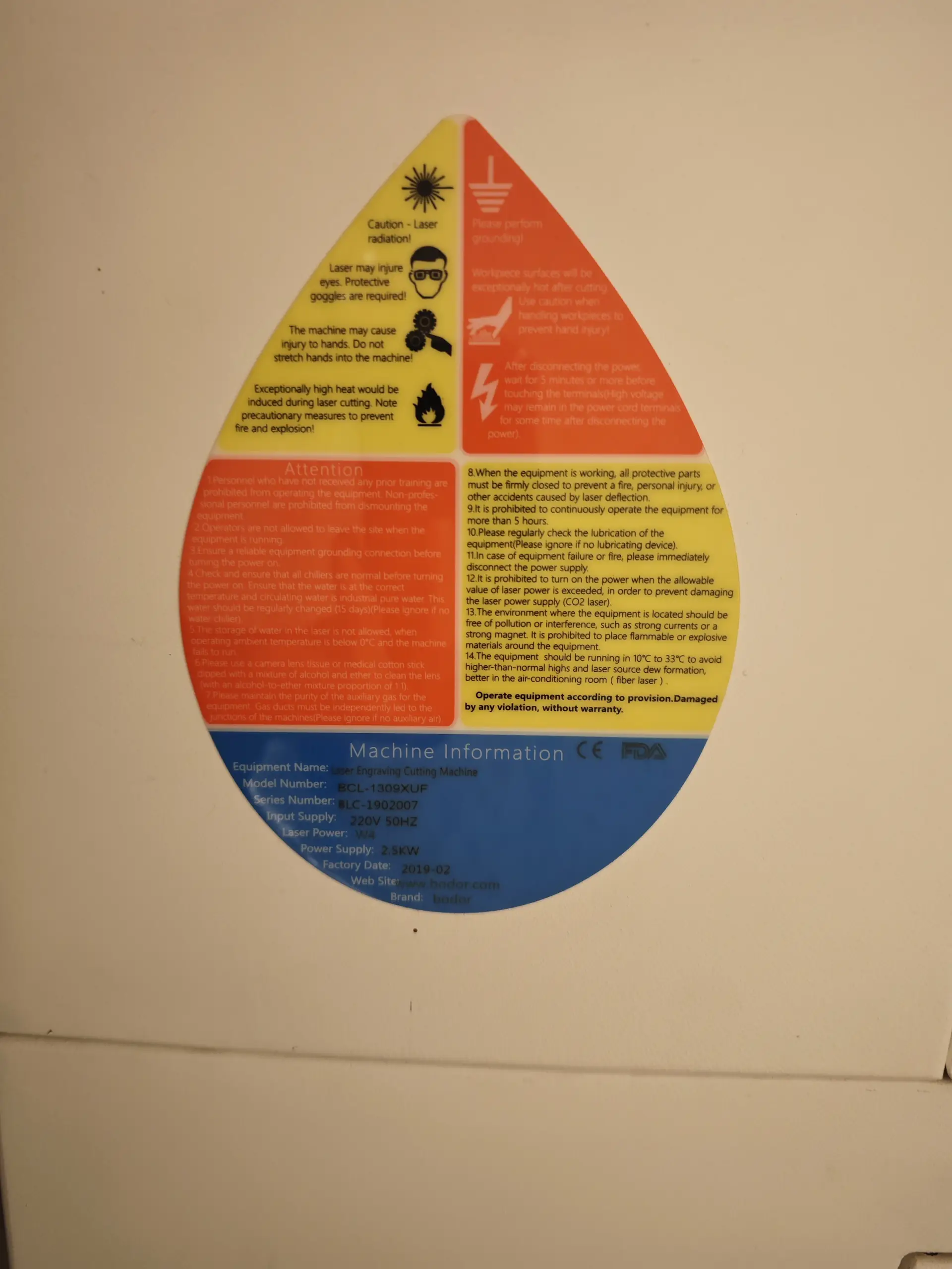
Machine Specifications Label
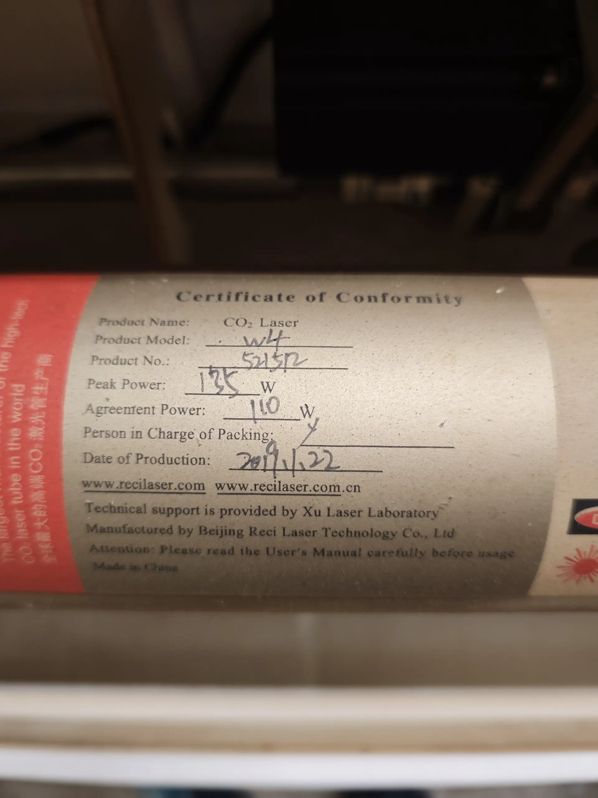
Reci W4 135W CO2 Laser Tube
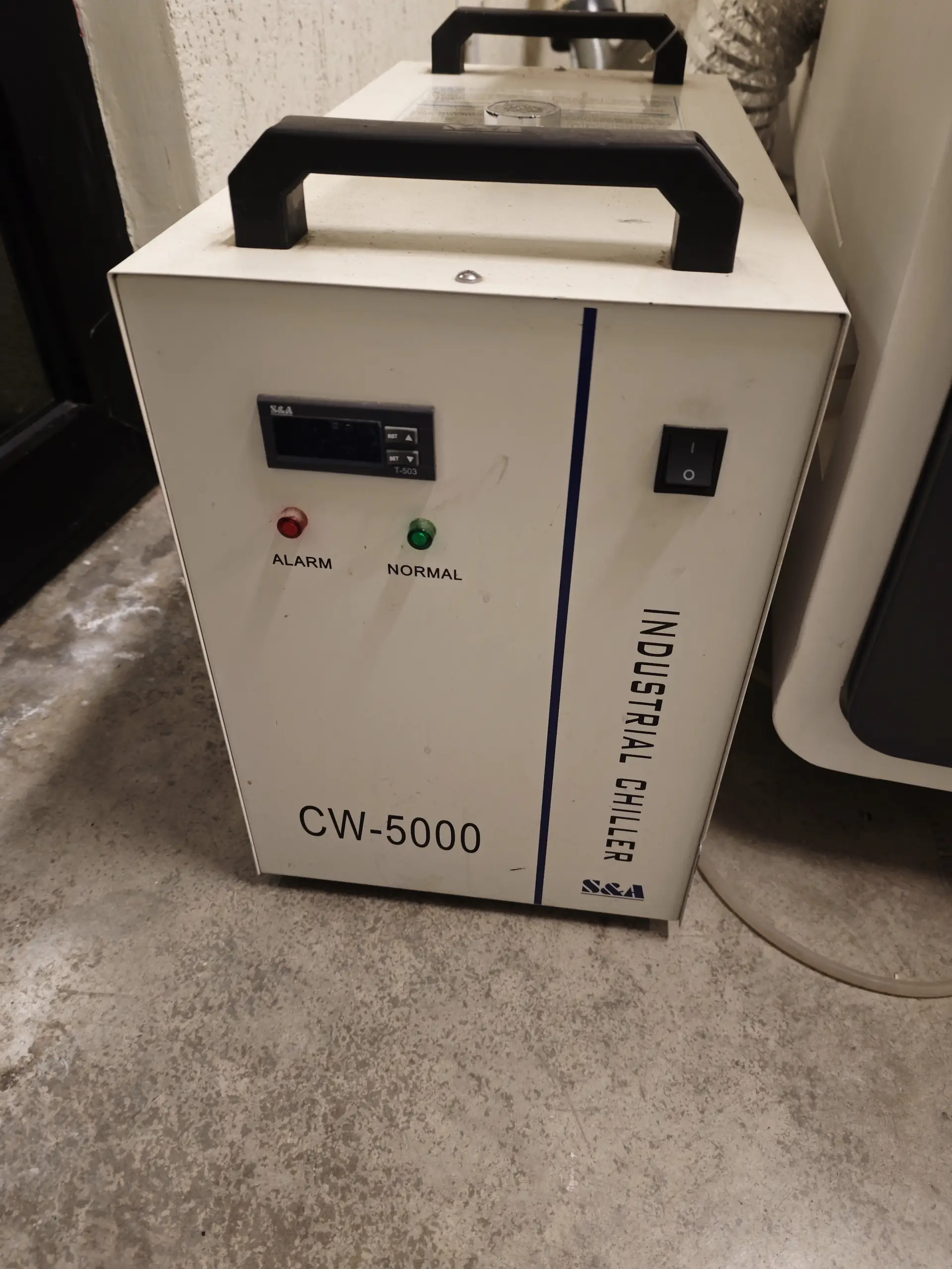
S&A CW-5000 Industrial Chiller
Machine Overview
- Model: Bodor BCL-1309XUF (1300mm x 900mm cutting bed)
- Laser Source: Beijing Reci Laser Technology Co., Ltd. Model W4 CO2 Glass Laser Tube (Peak Power: 135W, Agreement Power: 110W)
- Cooling System: S&A CW-5000 Industrial Water Chiller (recycles water to keep the tube below 22°C)
- Operating Software: RDWorks (via Wi-Fi/USB interface)
Kerf & Joint Characterization Test
Laser kerf is the width of material that is burned away by the laser beam during cutting. It is critical to measure
this value because it dictates how snug our press-fit slots will fit. To measure the kerf, we designed a slot
comb test block containing slots ranging from 3.7mm to 4.2mm.
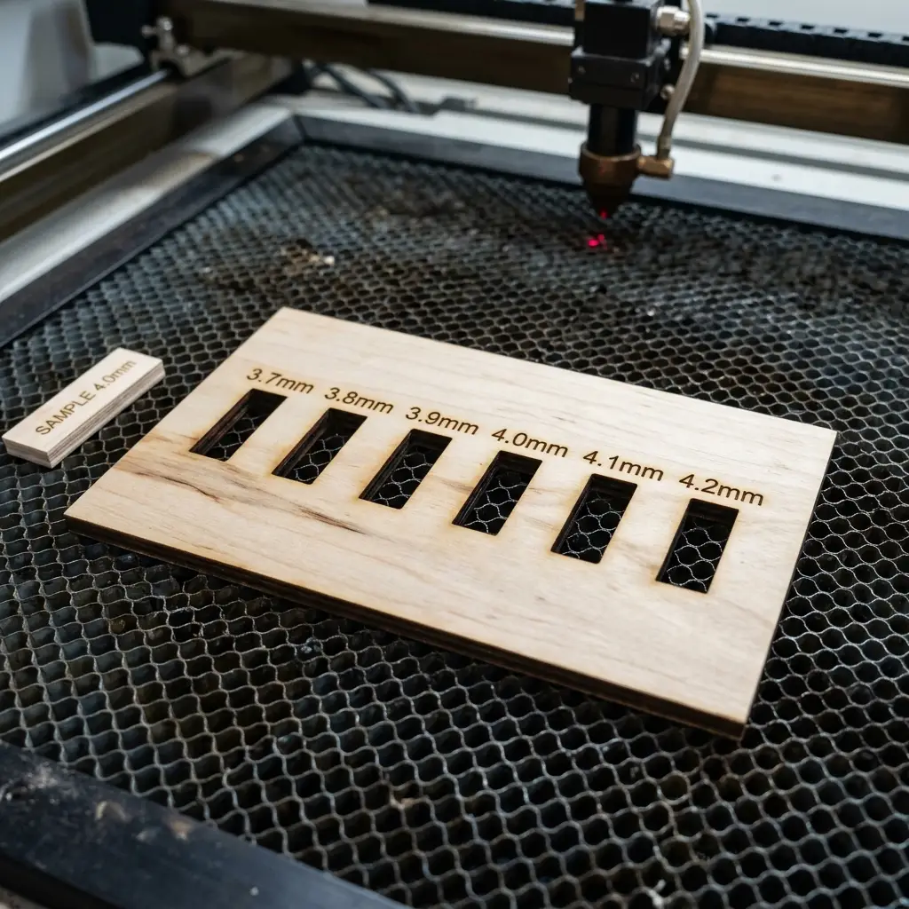
Characterization Workflow and Kerf Calculation:
-
Focus Calibration: Standardized focus distance by using a
7mmacrylic focal gauge spacer between the laser nozzle and the top of the cutting material. -
Kerf Measurement: We cut a rectangular strip measuring exactly
100.00 mmin width, containing 10 vertical cuts. By squeezing the resulting blocks together and measuring the combined width difference with calipers:
Measured Gap = 98.00 mm(Difference of 2.00 mm over 10 cuts)
Kerf = 2.00 mm / 10 cuts = 0.20 mm -
Clearance Determination: When designing a slot joint, the nominal socket size should be:
Slot Width = Material Thickness - Kerf. For a 4.0mm cardboard sheet, the target slot width is3.80mm.
Individual Assignment — Parametric Press-Fit Kit
Parametric Design Concept
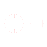
For my press-fit construction kit, I designed a modular geometrical connector block. The kit contains two main pieces: a circular center connector hub with slots offset at 45-degree angles, and a rectangular connector rod. I modeled this in Autodesk Fusion 360 using user parameters to handle dimensions dynamically.
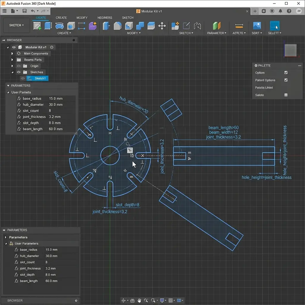
Parameters Table
material_thickness= 4.0 mmlaser_kerf= 0.20 mmslot_width=material_thickness - laser_kerf= 3.80 mmslot_depth= 10.0 mmhub_radius= 40.0 mm
Because the slots are bound to the slot_width parameter, if the material changes (e.g. to a 3.0mm board),
updating the material_thickness parameter will automatically adjust all slot cutouts across the entire sketch,
saving the trouble of manual scaling.
Fabrication and Assembly
I cut the pieces from a sheet of 4mm corrugated cardboard on the Bodor BCL-1309XUF laser cutter.
The cutting parameters utilized:
Cardboard Settings (4mm): Speed: 45 mm/s | Power: 35% | Frequency/Rate: 20000 Hz
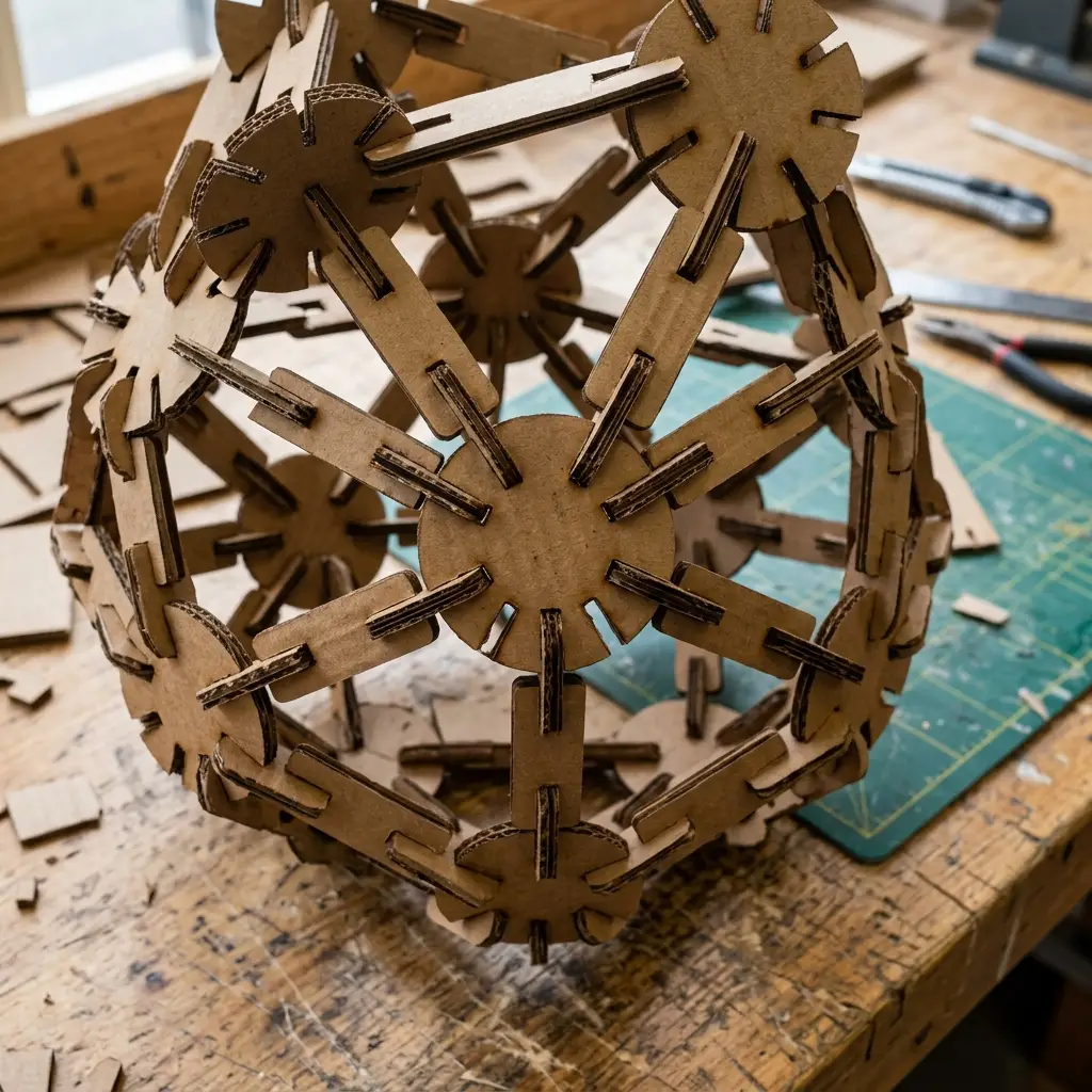
The resulting connectors hold together tightly due to the kerf compensation, allowing building complex 3D structures such as the geometric dome shown above. The parts stay rigid and do not collapse when lifted.
Vinyl Cutting Project
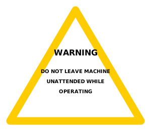
For the vinyl cutting assignment, I designed and fabricated a custom safety warning decal for our lab's laser cutter: "WARNING: DO NOT LEAVE MACHINE UNATTENDED WHILE OPERATING". This helps reinforce lab safety and satisfies the requirement of using the vinyl plotter to cut something useful.
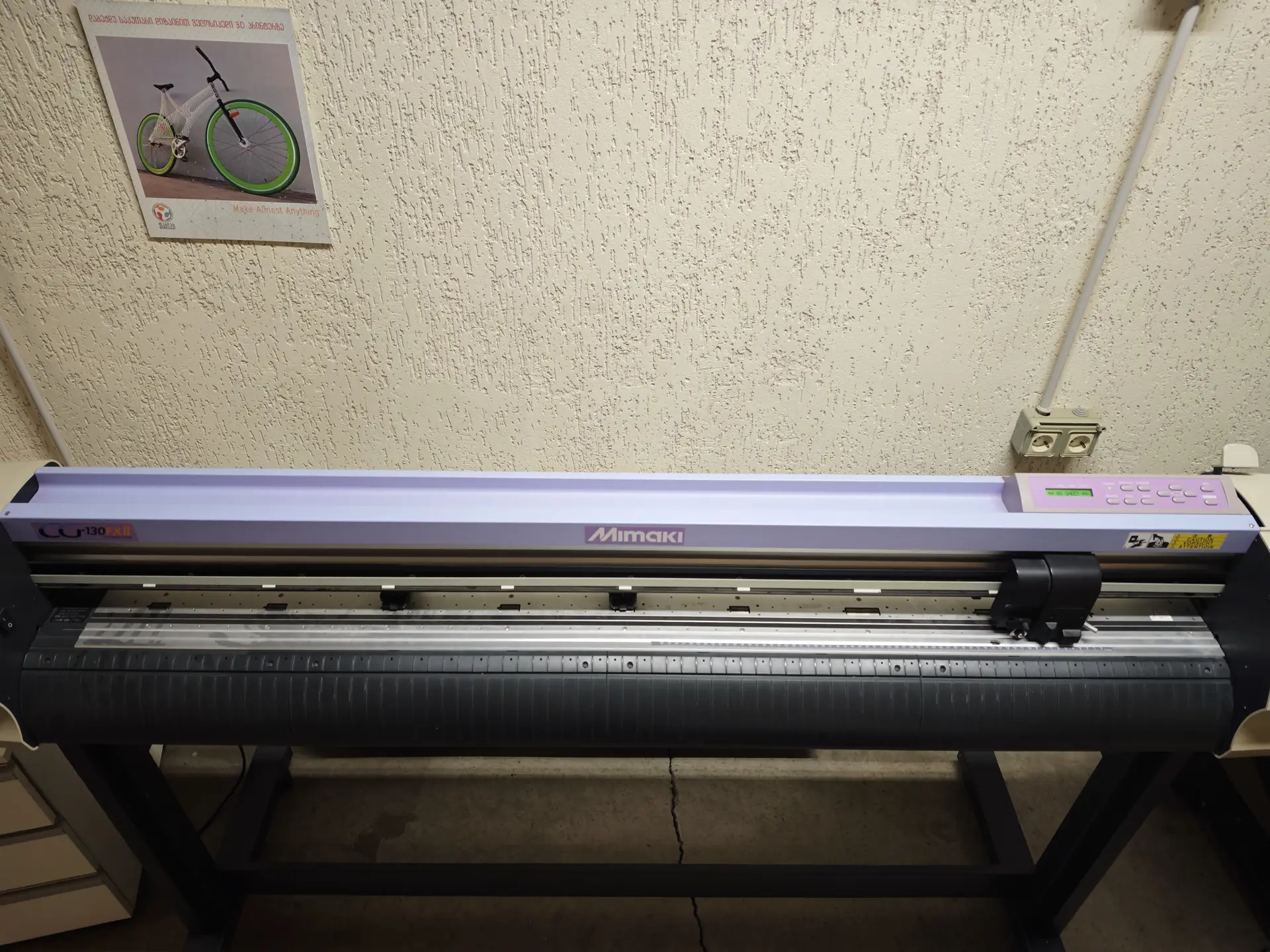
Mimaki CG-130FXII Plotter
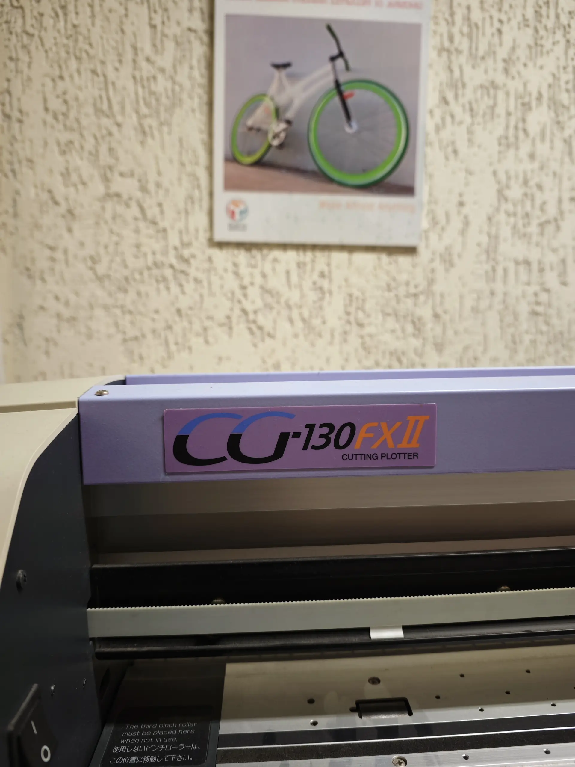
Plotter Brand Label
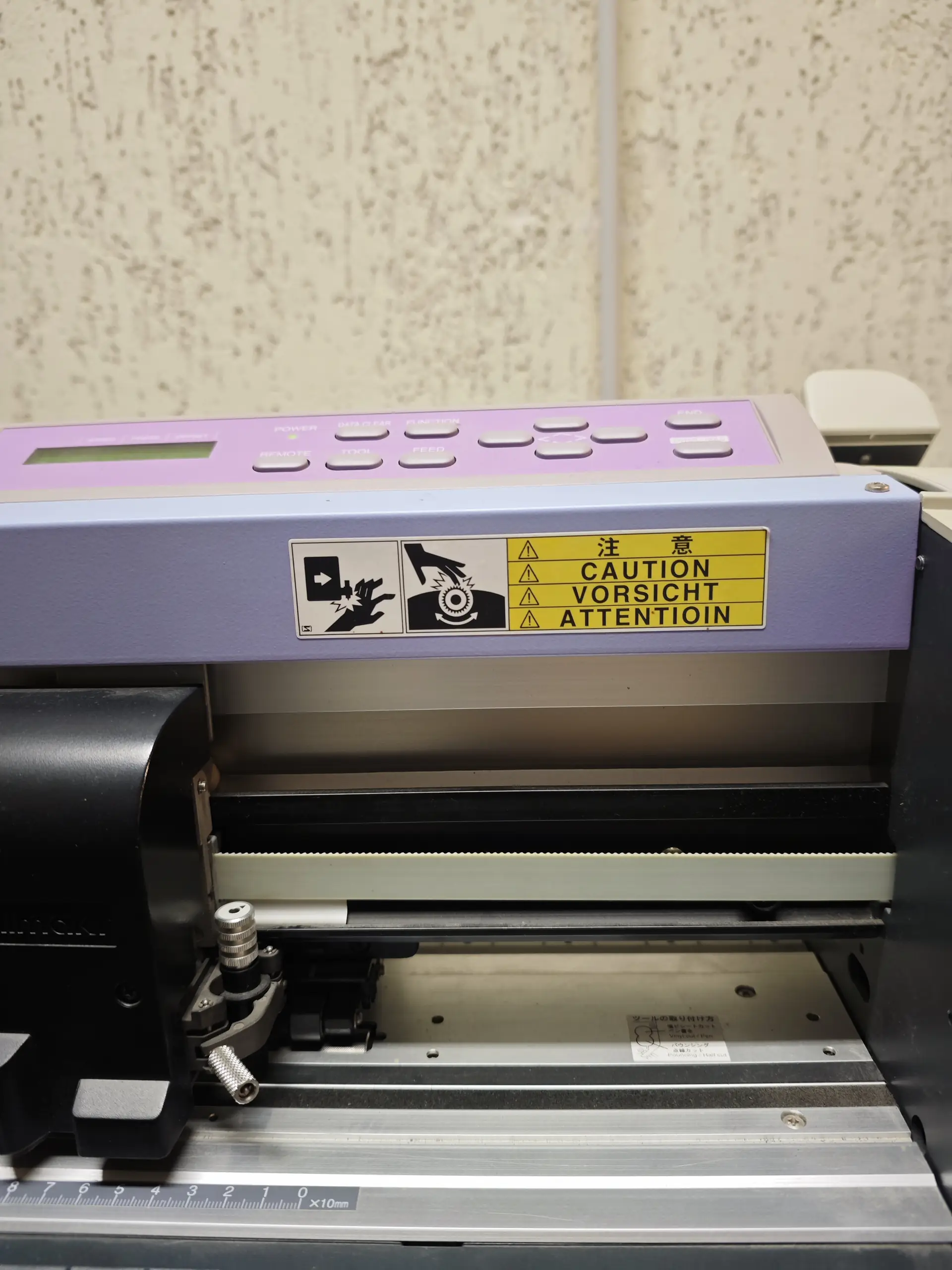
Tool Carriage Head
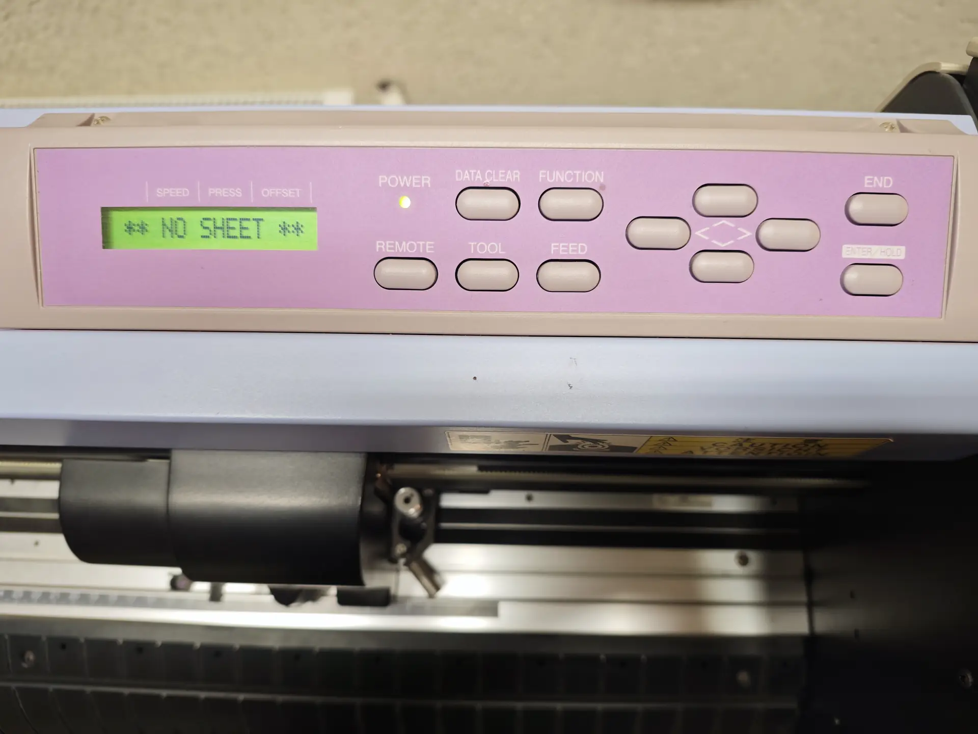
Control Panel Interface
Plotter Specifications & Materials
- Machine: Mimaki CG-130FXII (1300mm cutting width plotter)
- Material: 0.1mm high-gloss yellow adhesive vinyl roll
- Software: Inkscape + FineCut9 plug-in
Step-by-Step Cutting Workflow
-
Design Vector: Designed the safety sign in Inkscape by drawing a triangle and adding warning text. Converted all text to paths (
Path -> Object to Path) so the cutting software can follow the letter outlines. - Loading Material: Loaded the yellow vinyl sheet roll into the back rollers of the Mimaki plotter. Pulled the sheet forward, aligned it with the grid marks, and locked the rear pinch-roller clamps.
-
Plotter Initialization: Turned on the plotter. The screen displayed
** NO SHEET **(Image 4). Selected the Roll option on the panel, and the machine automatically scanned the media width. -
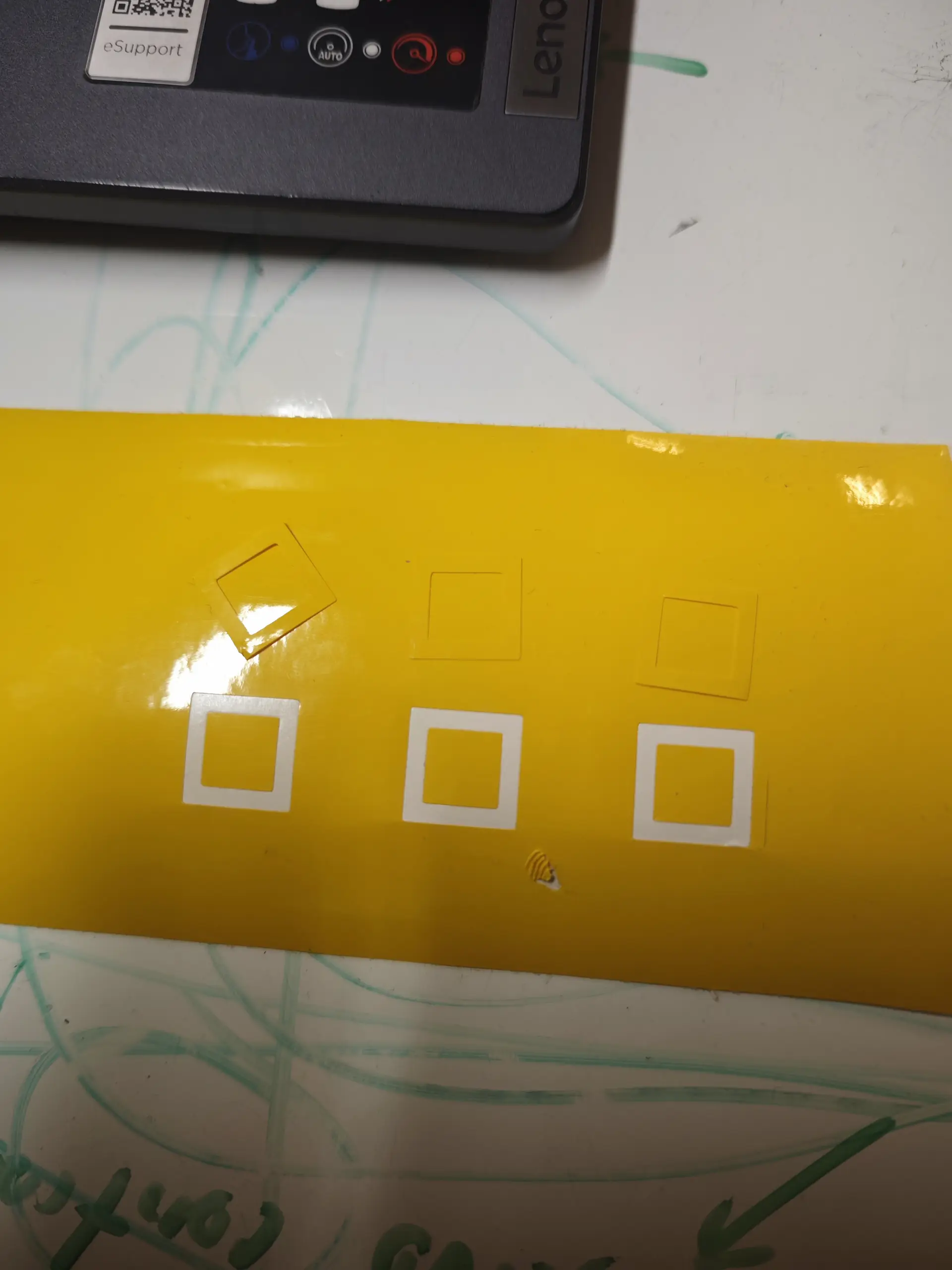
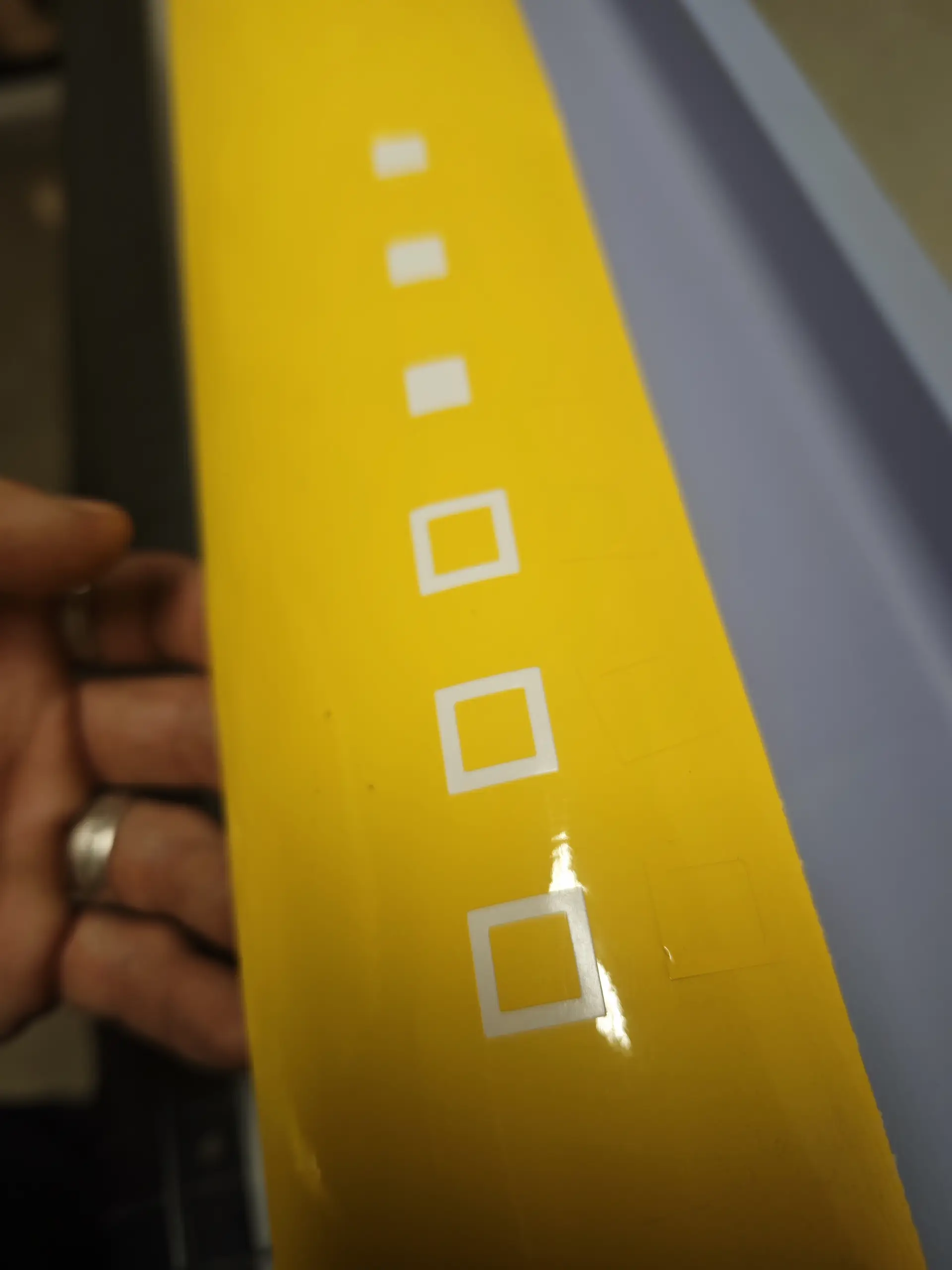
Calibration Cuts: Calibrated the cutter blade depth and cutting force. I ran test cuts of nested squares (shown in Images 5, 6, and 7) on the margin of the vinyl:
- If the square doesn't peel easily, blade force is too low.
- If the backing paper is cut, the blade force is too high.
- Optimal settings determined: Cut Speed:
20 cm/s| Cut Force:65 g| Blade Offset:0.25 mm.
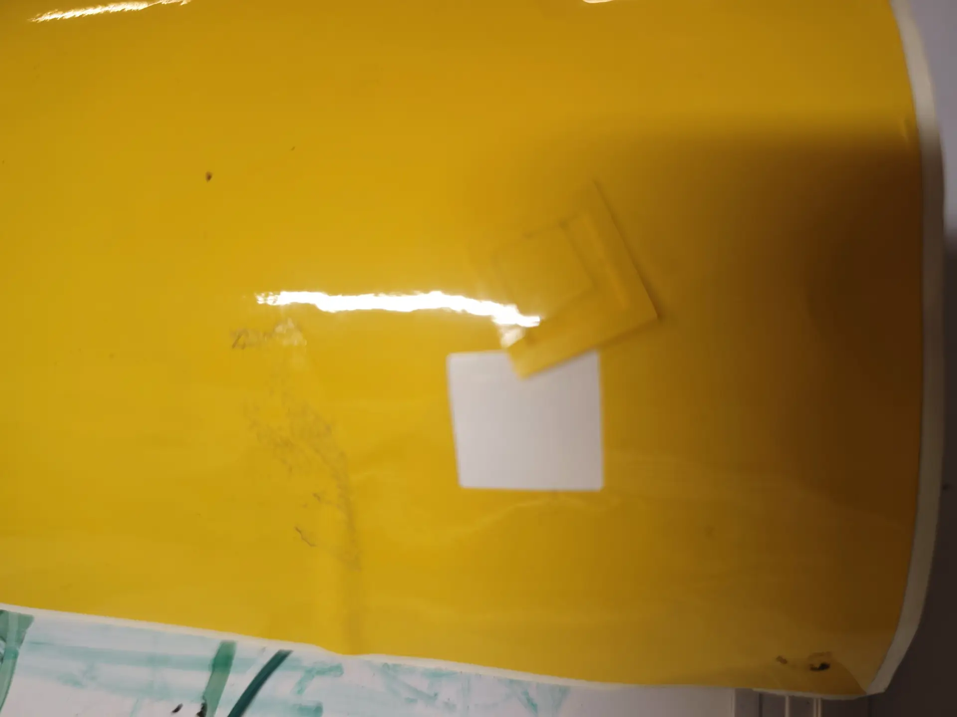
1. Calibration Square Test
2. Evaluating Peeling
3. Calibrated Margin Cuts
- Weeding and Transfer: Sent the job via FineCut. Once cut, I cut off the sheet section. I peeled away (weeded) the background yellow vinyl surrounding the letters and inside the triangle, leaving only the warning frame and letters. Then I applied transfer tape over the weeded decal, pressed it firmly with a squeegee, and peeled the backing paper off.
- Final Application: Cleaned the side surface of the Bodor laser cutter using isopropyl alcohol, carefully applied the transfer tape with the sticker, rubbed it down, and peeled back the transfer tape slowly.
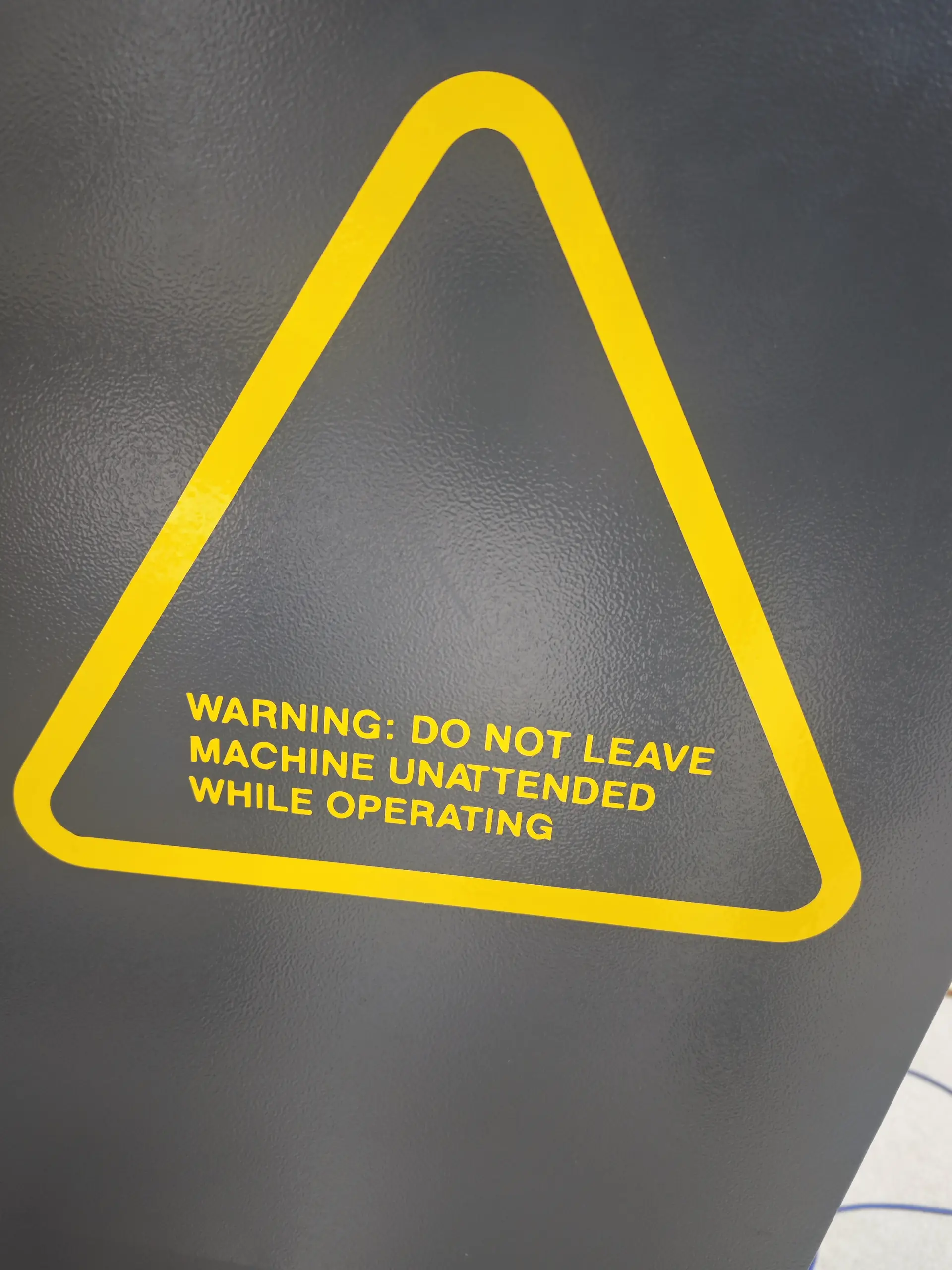
Original Design Files
Download the editable vector drawings and CAD project files produced for the Week 3 tasks:
| File Name | Format | Description | Download Link |
|---|---|---|---|
| pressfit_kit.svg | SVG (Vector) | Press-fit joint connector paths for laser cutting. | 📥 Download SVG |
| pressfit_kit.f3d | F3D (Fusion 360) | Parametric CAD assembly file for the press-fit pieces. | 📥 Download F3D |
| warning_sticker.svg | SVG (Vector) | Warning triangle sticker graphic design for the vinyl cutter. | 📥 Download SVG |
Have you answered these questions?
- Linked to the group assignment page?
Yes. The link is provided in the Group Assignment section. - Reflected on your individual page what you learned of your labs safety training?
Yes. Safety rules for the CO2 laser cutter (exhaust ventilation, fire extinguishing, material restrictions) are documented in the Safety Training section. - Explained how you created your parametric design?
Yes. The parametric joint and kerf parameters configured in Fusion 360 are explained in the Chassis Design section. - Documented how you made your press-fit construction kit?
Yes. Step-by-step laser parameters (Bodor laser cutter power/speed), kerf test (0.2mm), cutting, and assembly of the cardboard chassis kit are documented in the Press-Fit Kit section. - Documented how you made something with the vinyl cutter?
Yes. Designing, weeding, transferring, and plotting a transfer sticker on the Mimaki CG-130FXII plotter are documented in the Vinyl Cutting section. - Included your original design files?
Yes. Download links for cardboard CAD and vinyl vector files are included in the Design Files table. - Included hero shots of your results?
Yes. Hero shots of the assembled go-kart cardboard model and vinyl logo are displayed on the page.
Week 3 — Summary
This week focused on 2D digital fabrication via laser and vinyl cutting. Here is the checklist of accomplishments:
Safety and Specs
Completed lab safety training and characterized the Bodor BCL-1309XUF CO2 laser cutter and chiller.
Parametric Design
Designed a slotted construction kit in Fusion 360, compensating for the 0.2mm laser cut kerf.
Laser Fabricated
Cut and assembled a cardboard modular dome kit that fits snugly and stays together without adhesive.
Vinyl Cut Decal
Designed, calibrated, weeded, and transferred a safety warning vinyl sign onto the laser cutter body.