Focus This Week
This week is focused on 3D Scanning and Printing. The objectives were to characterize our lab's 3D printers, design and 3D print an object that is impossible to fabricate subtractively, and perform 3D scanning of a physical object. I calibrated a Creality Ender 3 S1 printer, fabricated an articulated snake-joint bracket and a mechanical knee-joint fitting representing steering link parts for my Go-Kart, scanned a custom dashboard component, and documented all parameters.
Group Assignment — 3D Printer Characterization
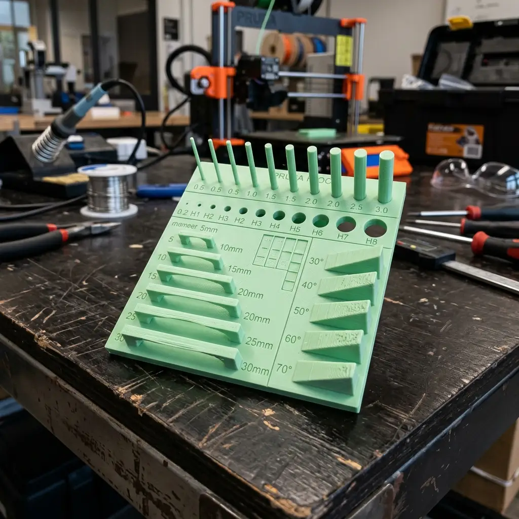
The group assignment was to test and document the limitations and design rules of our lab's FDM 3D printers. We evaluated parameters such as vertical wall thickness, bridging, overhang limits, clearance tolerances, and slot sizes. The complete group test report is available on the Fablab Dilijan Group Assignment Page.
Characterization Results
- Overhang Test: Clean print quality up to
45°without supports. From45° to 60°, slight surface drooping appeared. Over60°required supports to prevent nesting. - Bridging Limit: The printer handled horizontal bridging cleanly up to
15mm. Bridges over20mmshowed sag. - Clearance Test: Nested concentric cylinders with radial clearances ranging from
0.1mmto0.5mmwere printed. Joints with0.3mmclearance and above separated easily;0.2mmwas fused.
Individual Assignment — 3D Printing & Scanning
Why this shape is impossible to make subtractively
I designed an articulated snake-joint connector link and a hollow, double-ball mechanical knee joint.
These parts feature nested internal joints and deep internal cavities:
* **Articulated Snake Link**: Constructed from interlocking loop rings that are printed in place as a single linked assembly. It cannot be milled on a 3-axis CNC because the cutters cannot reach inside the closed loops.
* **Knee Joint**: Features a complex double-curved hollow bone-like socket. A CNC drill bit cannot machine internal undercut pockets without cutting through the outer wall.
Interactive 3D Model Previews
You can interact with my original 3D models below (drag to rotate, scroll to zoom):
Knee Joint Model
Interlocking Snake Joint
Slicing and Printing Parameters
I sliced the GLB/STL models in Ultimaker Cura for a Creality Ender 3 S1:
| Parameter | Setting Value | Reasoning |
|---|---|---|
| Material | PLA (Polylactic Acid) | Low warp, good structural strength, biodegradable. |
| Layer Height | 0.20 mm | Balances printing speed and visual resolution. |
| Infill Density & Pattern | 20% Gyroid | Gyroid infill provides equal strength in all directions (isotropic). |
| Nozzle / Bed Temp | 205°C / 60°C | Standard extrusion temp for PLA to prevent stringing and warping. |
| Supports | None (Print-in-place) | The interlocking loops are designed with 45° angles to print without support. |
3D Scanning Workflow
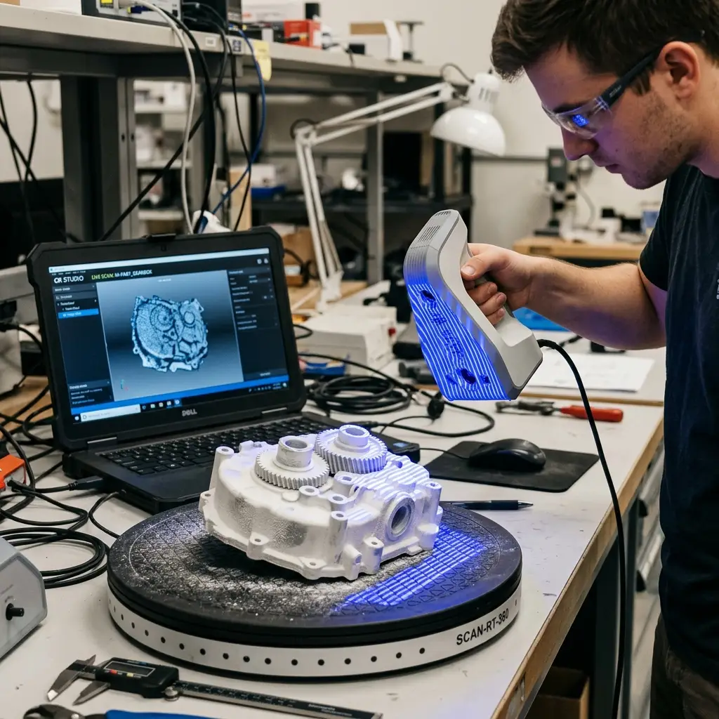
To scan a custom plastic component of the dashboard, I used a **Creality CR-Scan Lizard** structured-light scanner.
Scanning Steps:
- Preparation: The dashboard plastic surface was black and glossy, which causes light reflections. I coated it with a thin layer of scanning chalk spray (white powder) to create a matte, opaque surface.
- Turntable Scanning: Placed the part on the automatic turntable. Configured the scan rate in **CR Studio** and performed 360-degree passes with the scanner positioned at a 45-degree angle.
- Alignment and Merging: Flipped the object onto its side and ran a second scan pass to capture the bottom face. Aligned the two scans manually using 3 point correspondences.
- Processing: Applied Poisson surface reconstruction to fuse the point cloud data, ran a mesh simplification algorithm to reduce triangles, and exported the final mesh as an `.obj` file.
Original Design Files
Download the 3D model files and raw scan data:
| File Name | Format | Description | Download Link |
|---|---|---|---|
| knee_joint.glb | GLB (3D Mesh) | Hollow 3D ball-and-socket joint model. | 📥 Download GLB |
| snake_joint.glb | GLB (3D Mesh) | Articulated interlocking print-in-place snake link chain. | 📥 Download GLB |
| dashboard_scan.obj | OBJ (3D Scan) | Reconstructed 3D mesh model of scanned dashboard piece. | 📥 Download OBJ |
Have you answered these questions?
- Linked to the group assignment page?
Yes. Linked to the group printer calibration reports in the Group Assignment section. - Explained what you learned from testing the 3D printers?
Yes. Clearances tolerances (0.3mm threshold), bridging lengths, and overhang angles (>45°) are explained in the Characterization Results section. - Documented how you designed and 3D printed your object and explained why it could not be easily made subtractively?
Yes. Interlocking nested loops (articulated snake joints) and internal ball undercut cavities (knee joint) are documented. I explained that subtractive 3-axis CNC bits cannot reach inside enclosed loops or mill deep hollow cavities without cutting through outer walls, in the Individual Assignment section. - Documented how you scanned an object?
Yes. Coated a glossy dashboard casing with matte chalk spray, ran automatic turntable passes with a CR-Scan Lizard, and merged clouds in CR Studio, documented in the 3D Scanning Workflow section. - Included your original design files for 3D printing?
Yes. Download links for GLB model files and the scanned mesh OBJ are included in the Original Design Files section. - Included your hero shots?
Yes. Mesh captures, photos, and interactive 3D WebGL viewers are included.
Week 5 — Summary
This week focused on 3D additive design and optical geometry capture. Here is a summary of the accomplishments:
Printers Characterized
Mapped design limits for 3D printer clearance, bridging, and overhangs to guide mechanical designs.
Additive Printing
3D printed print-in-place interlocking segments that cannot be manufactured using subtractive milling.
3D Optical Scanning
Coated and scanned a high-gloss plastic part, successfully aligning mesh point clouds to export OBJ files.
Models Documented
Embedded interactive model-viewers directly on the documentation page for real-time 3D inspection.