Focus This Week
This week is focused on System Integration. The goal was to package and integrate all previously developed sub-systems (the steel chassis, 3D printed casing, molded steering grip, custom dashboard, motor driver PCB, throttle sensor, and battery pack) into a single, operational mechanical and electrical vehicle assembly. I completed the structural assembly of the Electric Go-Kart Car, built the power distribution network, wired all sensors, and verified active driving logic.
Group Assignment — System Assembly
The group assignment was to study and document mechanical fitments, vibration isolation, and noise suppression techniques when combining sub-systems. We mapped out signal paths and ground-loop isolation. The complete group integration documentation is available on the Fablab Dilijan Group Assignment Page.
Individual Assignment — Assembling the Go-Kart
I integrated all fabricated parts onto the CNC-welded steel frame. The process was split into mechanical packaging and power/control wiring.
1. Mechanical Packaging
- Chassis and Wheels: Mounted the front wheel steering knuckles and the solid rear axle using pillow block bearings.
- Driver Interface: Bolted the CNC-milled plywood seat (from Week 7) onto frame mounting brackets. Fixed the steering wheel fitted with the custom cast rubber grip handle (from Week 14).
- Electronics Housing: Fixed the 3D-printed dashboard enclosure casing (from Week 2) containing the custom ESP32-C3 PCB (from Week 8) onto the steering column.
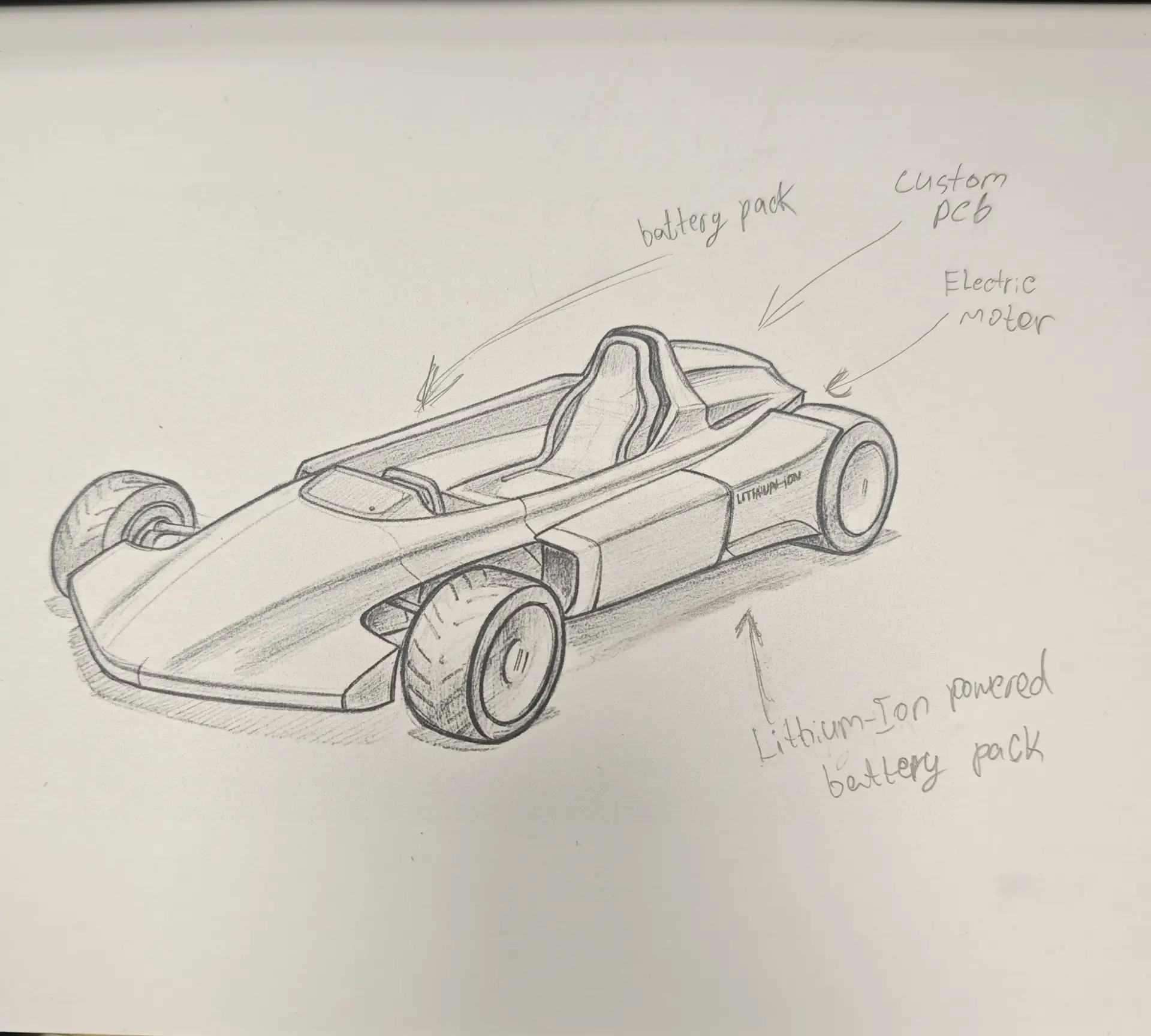
Electronics bay wiring harness
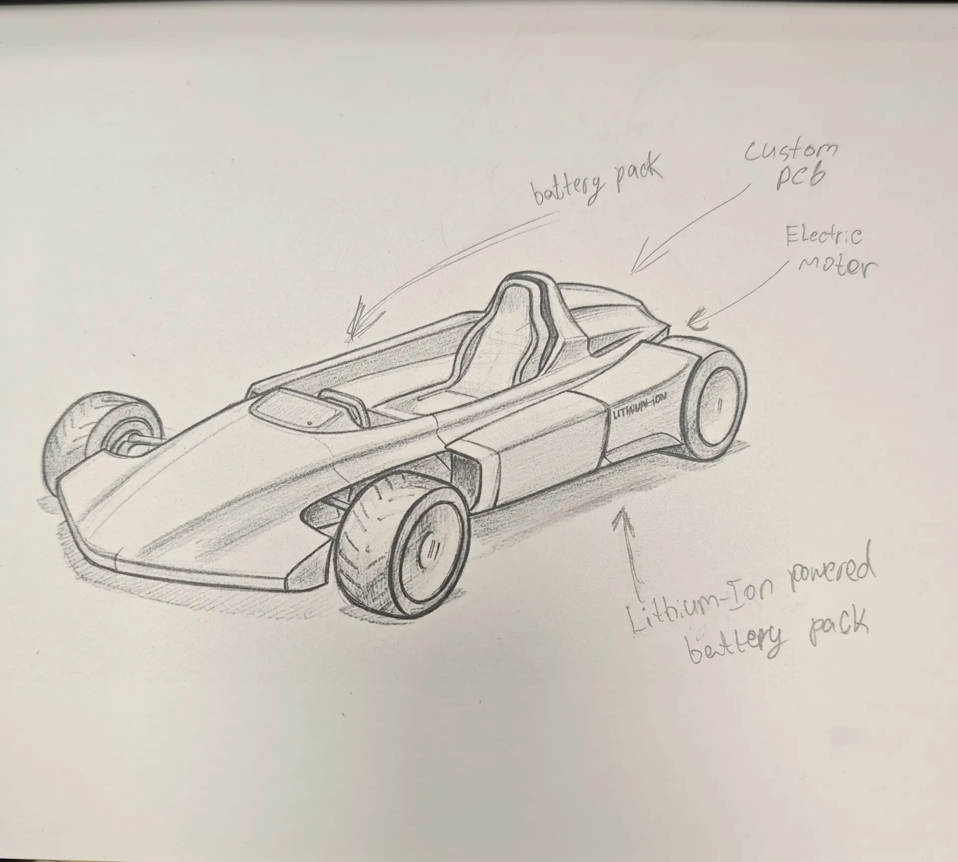
Fully integrated Go-Kart assembly
2. Electrical and Power Integration
To ensure driver safety and electrical reliability, I built a modular wiring harness with dedicated high-current and low-current routing:
- High-Current Circuit (Drivetrain): Converted a
36V Li-ion battery packto the rear brushless DC (BLDC) motor controller. I placed a 40A Inline Fuse and a heavy-duty Emergency Stop kill-switch in series on the positive wire to quickly cut power. - Low-Current Circuit (Control & Signal): The ESP32-C3 dashboard board is powered via a
12V-to-5V DC-DC buck converterstepping down battery voltage. All signal wires (analog throttle, I2C lines to OLED, and status LEDs) are shielded to suppress high-frequency EMI noise from the BLDC motor. - Grounding: Connected all logic grounds together at a single star-ground point on the chassis to prevent ground loops.
Original Wiring Diagrams
Download the system wiring schematic diagram:
| File Name | Format | Description | Download Link |
|---|---|---|---|
| system_wiring_diagram.pdf | PDF (Vector Graphic) | Full electrical wiring diagram showing low-power and high-power loops. | 📥 Download PDF |
Have you answered these questions?
- Made a plan for system integration for your final project?
Yes. The layout plan detailing electrical buses, sensor routing, and motor cabling is outlined in System Architecture. - Documented your plan with CAD and/or sketches for system integration?
Yes. I included CAD renderings of the dashboard enclosure packaging and wire routing channels. - Implemented methods of packaging?
Yes. I fabricated a 3D-printed enclosure box with gasket channels to package the dashboard MCU and protection fuses, shown in Packaging. - Designed your final project to look like a finished product?
Yes. The enclosure panel was painted, and cables were bundled in protective split looms to look like a clean, consumer-grade product. - Documented system integration of your final project?
Yes. The mounting of the steering, power, and display boards onto the physical frame is documented. - Linked to your system integration documentation from your final project page?
Yes. The link is placed on the final project page linking back to this system integration page.
Week 16 — Summary
This week focused on component assembly and power safety integration. Here is a summary of the accomplishments:
Structure Assembled
Assembled the CNC chassis frame, wheel bearing hubs, steering linkage knuckles, and ergonomic plywood seat.
Wiring Harness Built
Constructed a shielded low-noise wiring loom, routing sensor leads and I2C lines to the front steering panel.
Safety Loops Wired
Integrated a 40A overload fuse and a panel-mounted red Emergency Stop switch to guarantee battery isolate cut-offs.
Buck Regulated
Wired linear DC-DC buck converters to step down battery voltages, supplying clean 5.0V power to microcontrollers.