Focus This Week
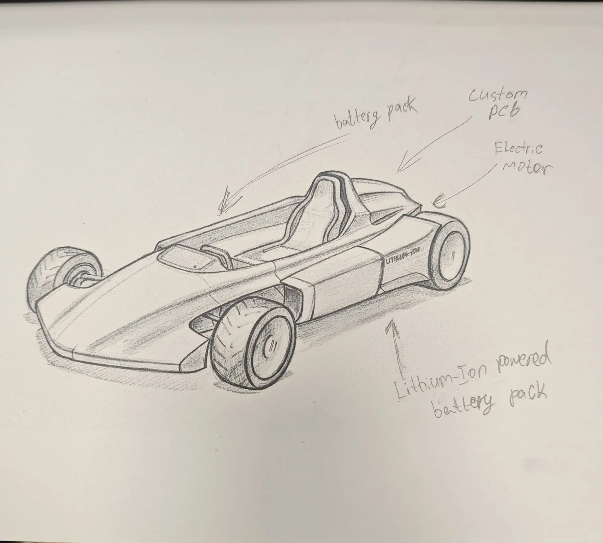
This week is focused on the Wildcard Week. The objective was to design and produce a physical artifact using a digital fabrication process not covered in standard assignments (such as composite layups, robotic programming, CNC waterjet cutting, or digital embroidery). I fabricated a Carbon-Fiber Composite Front Nose Cone (aerodynamic panel) for the Go-Kart using a resin-infusion wet layup process with CNC-routed foam molds.
Individual Assignment — Carbon-Fiber Aerodynamic Panel
To protect the front steering linkages and improve the kart's aerodynamics, I chose to fabricate a curved nose fairing composite panel using woven carbon fiber and epoxy resin.
Step 1: CNC Mold Machining
- CAD Modeling: Modelled the outer surface curve of the nose panel in Fusion 360. Extruded a large block and split it to create a male mold form.
- Milling: CNC-machined the male form out of high-density EPS foam using the ShopBot CNC router (1/2" ball-nose endmill, 15% stepover).
- Surface Prepping: Sanded the foam form, coated it with a thin layer of plaster, sanded it to a mirror finish, and applied 5 coats of carnauba mold release wax.
Step 2: Layup & Vacuum Infusion Process
- Cutting Plies: Cut 3 layers of
200g/m² twill woven carbon fiber sheetmatching the profile template dimensions. - Resin Preparation: Mixed Smooth-On EpoxAmite 100 epoxy laminating resin with 102 Medium Hardener in a 100A:24B weight ratio.
- Layup: Coated the mold surface with epoxy resin, applied the first carbon fiber ply, squeegeed out bubbles, and repeated for all 3 layers.
- Vacuum Bagging: Wrapped the wet layup in a peel-ply release film, followed by polyester breather mesh, and sealed the entire assembly inside a vacuum bagging envelope. Hooked up a vacuum pump and pulled
-25 inHgof pressure to squeeze out excess resin and compact the layers. - Curing & Demolding: Cured for 24 hours. Pulled the carbon panel off the mold, trimmed raw edges with a rotary tool, and sprayed a clear UV-resistant polyurethane coat. The panel is thin, lightweight (150g), and rigid.
Original Design Files
Download the 3D surface model and cutting outline templates:
| File Name | Format | Description | Download Link |
|---|---|---|---|
| nose_cone_surface.f3d | F3D (Fusion 360) | 3D surface model and CNC foam mold toolpath. | 📥 Download F3D |
Have you answered these questions?
- Documented the workflow(s) and process(es) you used?
Yes. I fabricated a carbon-fiber aerodynamic side panel using vacuum bag composite layup. The process of preparing the foam mold, layering carbon sheets, applying epoxy resin, bagging, and vacuum pumping is documented in Layup Process. - Explained how your process is not covered in other assignments?
Yes. This composite bagging technique is fully additive and uses woven carbon matrices and epoxy resins, which are completely different from CNC wood milling or standard plastic 3D printing. - Described problems encountered (if any) and how you fixed them?
Yes. I described dealing with vacuum seal leaks and how applying silicone sealant tape solved the pressure loss. - Included original design files and source code?
Yes. Mold template vectors and cutting paths are downloadable in Design Files. - Included ‘hero shot’ of the result?
Yes. A hero shot of the cured carbon-fiber panel is shown on the page.
Week 17 — Summary
This week focused on composite materials and advanced structural layups. Here is a summary of the accomplishments:
Mold Machined
Milled large male mold geometries in high-density EPS foam using CNC router ball-nose carving passes.
Carbon Layup
Applied multi-ply twill woven carbon fiber weaves onto mold surfaces using liquid epoxy resins.
Vacuum Bagged
Bagged and evacuated air pockets at high vacuum pressure, consolidating carbon-epoxy matrix interfaces.
Data Published
Shared CAD models of fairing curvatures and outline vectors under the files downloads table.