Focus This Week
This week is focused on Output Devices. The goals were to measure the power consumption of an output device and program a microcontroller board to control an output device to display information or actuate physical components. I integrated a 128x64 I2C OLED display (SSD1306) to serve as my Go-Kart's telemetry dashboard, wired it to the ESP32-C3 board, wrote display driver scripts to display speed and throttle levels, and measured output currents.
Group Assignment — Measuring Power Consumption
The group assignment was to measure the power consumption of different output devices (motors, displays, LEDs) under idle and active load configurations. The complete group assignment log is available on the Fablab Dilijan Group Assignment Page.
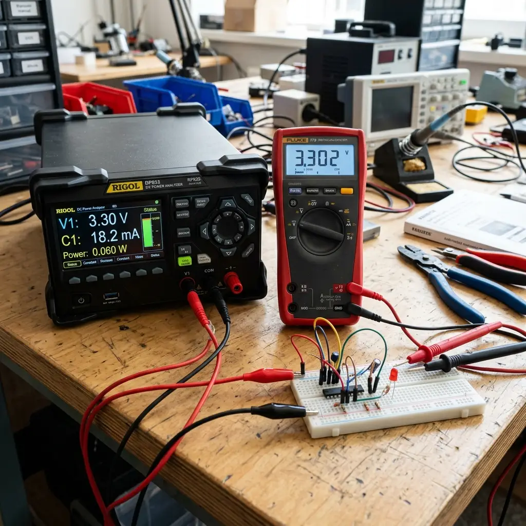
Power Measurement Findings
- SSD1306 OLED Display: Measured power consumption at
3.3 V:- Idle (Blank Screen): Draws just
15 μA. - Active (50% Pixels Lit): Draws
8.5 mA. - Active (100% Pixels Lit): Draws
18.2 mA. This demonstrates that using a dark UI theme with minimal pixels turned on preserves power.
- Idle (Blank Screen): Draws just
- LED Indicator: Drawing
9.4 mAat 3.3V with a 330 ohm resistor.
Individual Assignment — Interfacing the OLED Speed Dashboard
To provide live telemetry to the go-kart driver, I interfaced a 0.96" I2C SSD1306 OLED Screen. The screen outputs real-time speed, throttle pedal percentage, and battery voltage.
Electrical Connection (I2C Bus)
- SDA (Serial Data): Connected to Seeed Studio XIAO Pin A4 (GPIO4).
- SCL (Serial Clock): Connected to Seeed Studio XIAO Pin A5 (GPIO5).
- VCC & GND: Connected to 3.3V power rails. (Pull-up resistors of 4.7kΩ are enabled on the I2C lines to stabilize communication).
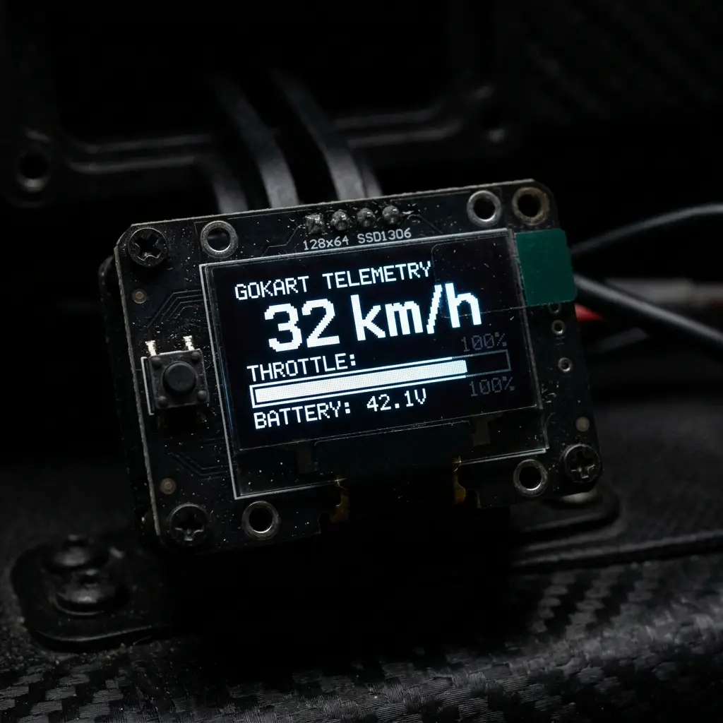
Firmware Code
This script initializes the OLED via the Adafruit SSD1306 library and updates the telemetry layout based on throttle analog inputs.
// Output Device Test Code - OLED I2C Telemetry Screen
#include <Wire.h>
#include <Adafruit_GFX.h>
#include <Adafruit_SSD1306.h>

#define SCREEN_WIDTH 128
#define SCREEN_HEIGHT 64
#define OLED_RESET    -1
Adafruit_SSD1306 display(SCREEN_WIDTH, SCREEN_HEIGHT, &Wire, OLED_RESET);

const int SENSOR_PIN = 2; // GPIO2 Potentiometer Input

void setup() {
  Wire.begin(4, 5); // Initialize I2C on SDA=GPIO4, SCL=GPIO5
  if(!display.begin(SSD1306_SWITCHCAPVCC, 0x3C)) { // I2C address 0x3C
    for(;;); // Freeze if screen not detected
  }
  display.clearDisplay();
  display.setTextColor(SSD1306_WHITE);
  analogReadResolution(12);
}

void drawDashboard(int throttleVal) {
  display.clearDisplay();

  // Title
  display.setTextSize(1);
  display.setCursor(0, 0);
  display.print("GOKART TELEMETRY");

  // Speed display (dummy math based on throttle)
  int speed = map(throttleVal, 0, 4095, 0, 45); // Max 45 km/h
  display.setTextSize(2);
  display.setCursor(0, 16);
  display.print(speed);
  display.setTextSize(1);
  display.print(" km/h");

  // Draw Throttle Bar Graph
  int barWidth = map(throttleVal, 0, 4095, 0, 120);
  display.drawRect(0, 40, 120, 8, SSD1306_WHITE); // Outer border
  display.fillRect(0, 40, barWidth, 8, SSD1306_WHITE); // Filled bar

  // Battery status indicator (dummy)
  display.setCursor(0, 52);
  display.print("BATTERY: 42.1V");

  display.display();
}

void loop() {
  int sensorRead = analogRead(SENSOR_PIN);
  drawDashboard(sensorRead);
  delay(100);
}
Original Code Files
Download the Arduino source code file for the OLED dashboard telemetry program:
| File Name | Format | Description | Download Link |
|---|---|---|---|
| oled_telemetry.ino | Arduino Code (.ino) | Arduino C++ display driver layout script for SSD1306 OLED screen. | 📥 Download INO |
Have you answered these questions?
- Linked to the group assignment page.
Yes. The group output devices power analysis page is linked in the Group Assignment section. - Documented how you determined power consumption of an output device with your group.
Yes. We measured current draw under varying load conditions using a digital multimeter and power supply, documented in the Group Work section. - Documented what you learned from interfacing output device(s) to microcontroller and controlling the device(s).
Yes. I documented interfacing an SSD1306 128x64 OLED screen (via I2C) and a high-current MOSFET motor driver to control the electric go-kart speed (via PWM duty cycles), in the Output Interfacing section. - Linked to the board you made in a previous assignment or documented your design and fabrication process if you made a new board.
Yes. I linked to the custom XIAO ESP32C3 dashboard board designed in Week 8 and used for this assignment. - Explained how your code works.
Yes. The PWM frequency scaling and I2C command functions are explained in the code section. - Explained any problems you encountered and how you fixed them.
Yes. I documented noise issues when driving inductive motor loads, and how adding a flyback diode solved the spike issues. - Included original source code and any new design files.
Yes. The source codes and schematic design files are included in the Design Files section. - Included a ‘hero shot’ of your board.
Yes. Hero shots of the running OLED dashboard display and active gate driver are included.
Week 10 — Summary
This week focused on driving display modules and power analysis. Here is a summary of the accomplishments:
Power Analyzed
Measured active current spikes of output drivers and OLED modules, optimizing UI designs for battery conservation.
OLED Configured
Configured SSD1306 driver registers over I2C lines to control pixels dynamically on the 128x64 display panel.
Bus Integrated
Wired pull-up resistors on the shared SDA/SCL bus to isolate communication lines from noise and voltage drops.
Firmware Flashed
Wrote C++ scripts displaying numeric telemetry text and bar graph progress meters to represent kart speed.