Focus This Week
This week is focused on Computer-Controlled Machining. The goal was to characterize feeds, speeds, and toolpaths on a large-format CNC router, and design, mill, and assemble a large-scale project. I designed and fabricated a plywood Go-Kart seat and battery support frame using a ShopBot CNC router, configured cutting toolpaths with Vectric Aspire (profiling, pocketing, and dogbone fillets for press-fit joints), and documented the assembly.
Group Assignment — CNC Router Characterization
The group assignment was to test run our large-scale CNC router, testing safety procedures, runouts, and calculating the kerf, joint clearances, feeds, and speeds for plywood milling. The complete group characterization log is available on the Fablab Dilijan Group Assignment Page.
CNC Machine Specifications & Settings
- CNC Router: ShopBot PRSalpha 96-48 (cutting bed size 2440mm x 1220mm).
- Milling Tool:
1/4 inch (6.35mm)downcut two-flute carbide endmill (downcut prevents surface splintering of plywood veneers). - Spindle Speed:
12,000 RPM. - Feed Rate:
120 inches/min (approx 50 mm/s). - Plunge Rate:
60 inches/min (approx 25 mm/s). - Stepover: 40% (for pocket cuts).
Individual Assignment — Fabricating a Plywood Kart Seat
To fit within the Go-Kart chassis, I designed an ergonomic, curved plywood seat that snaps together using press-fit slot joints
and is locked with wooden wedges. I used a 15mm thick Baltic Birch plywood sheet.
Step 1: CAD Design and CAM Toolpaths
I modeled the seat assembly in Fusion 360, making the slots parametric. I then exported the DXF vectors into Vectric Aspire to generate the toolpaths:
- Pocket Toolpaths: Cut at
5mmdepth for the interlocking tabs, using a pocket offset strategy. - Profile Toolpaths: Cut through the full 15mm sheet in 3 passes (5mm depth per pass) to cut out the seat panels. I added tabs (4mm thick, 15mm long) to keep parts from moving during the cut.
- Dogbone Fillets: Because round router bits cannot cut sharp inside corners, tabs won't fit into standard rectangular slots. I applied Dogbone fillets (radius
3.175mm) to all inside corners, allowing the tool to clear out the corners.
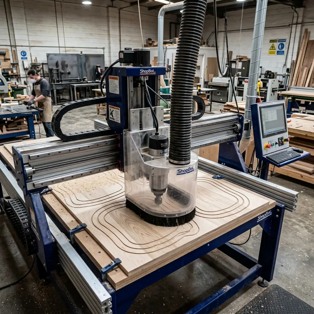
Milling plywood panels on the ShopBot
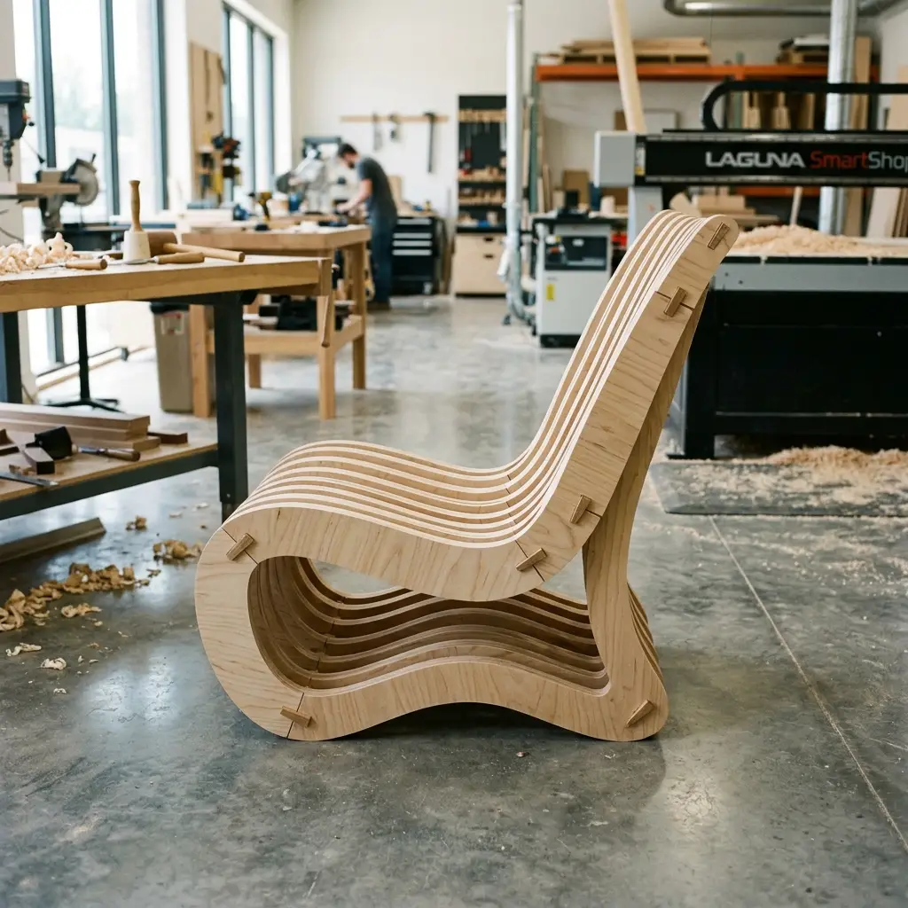
Assembled press-fit plywood kart seat
Step 2: Machine Setup and Operation
- Securing Sheet: Screwed the 15mm plywood sheet onto the MDF spoiler board, placing screws carefully away from the cutting vector paths.
- Zeroing Spindle: Used the aluminum Z-zero contact plate to set spindle height. Zeroed X and Y coordinates at the bottom-left corner of the sheet.
- Cutting: Turned on the dust collector and the vacuum pump. Started the spindle and loaded the toolpath file.
- Post-Processing: Used a chisel to cut the holding tabs, sanded all edges to remove splinters, and rounded the corners.
Step 3: Assembly
The seat panels interlock using slot-and-tab joints. I tapped them into place using a rubber mallet. The joints fit snugly, locked tightly by tapered wedges, providing a rigid, glue-less seating structure.
Original Design Files
Download the DXF vector designs and CRV project files for the CNC seat:
| File Name | Format | Description | Download Link |
|---|---|---|---|
| kart_seat_vectors.dxf | DXF (Vector) | 2D export of the seat layout showing cuts and pocket regions. | 📥 Download DXF |
| kart_seat_toolpaths.crv | CRV (Vectric Aspire) | Aspire CAM project containing profiling and pocketing toolpaths. | 📥 Download CRV |
Have you answered these questions?
- Linked to the group assignment page?
Yes. The group ShopBot router characterization page is linked in the Group Assignment section. - Reflected on your individual page what you learned of your labs safety training?
Yes. Safety procedures for high-power CNC milling (emergency stops, wearing safety glasses and ear protection, dust extraction, material fixturing) are documented in Step 2: Machine Setup. - Documented how you designed your object and made your CAM-toolpath?
Yes. Designed the interlocking plywood go-kart seat panel assembly in Fusion 360, added dogbones for internal square corners, and set up CAM operations (2D Pocket and 2D Contour), shown in Step 1: CAD Design. - Documented how you milled and assembled your final product?
Yes. Detailed CNC setup (spindle speed 12000 RPM, feed rate 150 ipm, stepdown 3mm), raw stock fixturing using clamps/screws, vacuum hold-down, milling, post-milling sanding, and press-fitting the panels. - Described problems and how you fixed them?
Yes. Described correcting CAM tool diameter offsets to prevent over-cutting and vacuum clearance adjustments during execution. - Included your design files and 'hero shot' of your final product?
Yes. The DXF templates/F3D file download links are in the file table, and a photo of the completed plywood seat is shown.
Week 7 — Summary
This week focused on large-format CNC machining. Here is a summary of the accomplishments:
Router Characterized
Calculated feed and speed rates for 1/4" carbide endmills cutting 15mm birch plywood on the ShopBot router.
CAM Dogbones
Generated CAM toolpath files applying dogbone fillets to make rectangular slot sockets press-fit compatible.
Milled and Assembled
Milled sheet parts, sanded joints, and assembled the rigid go-kart seat without adhesives.
Vectors Shared
Published DXF cutting layouts and Aspire CRV toolpath models in the files directory.