Focus This Week
This week is focused on Electronics Production. The objectives were to characterize the design rules of our PCB milling workflow, fabricate my custom ESP32-C3 microcontroller board designed in Week 6, solder the surface-mount components, and program the board to verify that the circuit works. I milled my board using a Roland SRM-20 CNC machine, soldered the SMD parts using reflow and hand-soldering techniques, and tested it successfully.
Group Assignment — PCB Milling Characterization
The group assignment was to characterize the mechanical resolution of our lab's PCB fabrication workflow by milling a test pattern with lines of varying widths. The complete group characterization report is available on the Fablab Dilijan Group Assignment Page.
Lab Workflow & Settings
- Milling Machine: Roland SRM-20 Desktop Mill (high-speed spindle, max 15,000 RPM).
- Toolpath Generator: **Mods CE** (mods.fabcloud.org) to convert KiCad SVG trace exports into Roland RML G-code commands.
- Trace Cutters:
1/64 inchflat endmill for routing traces. Feed rate:4 mm/s, Cut depth:0.1 mm. - Outline Cutters:
1/32 inchflat endmill to cut board edges. Feed rate:2 mm/s, Cut depth:0.5 mm(multi-pass).
Individual Assignment — Board Production & Testing
I fabricated the ESP32-C3 dashboard development board using a single-sided FR-4 copper-clad PCB sheet.
Step 1: CNC Mechanical Milling
I exported the board traces and edge outlines from KiCad as SVG files, loaded them into Mods CE, and generated the RML toolpaths.
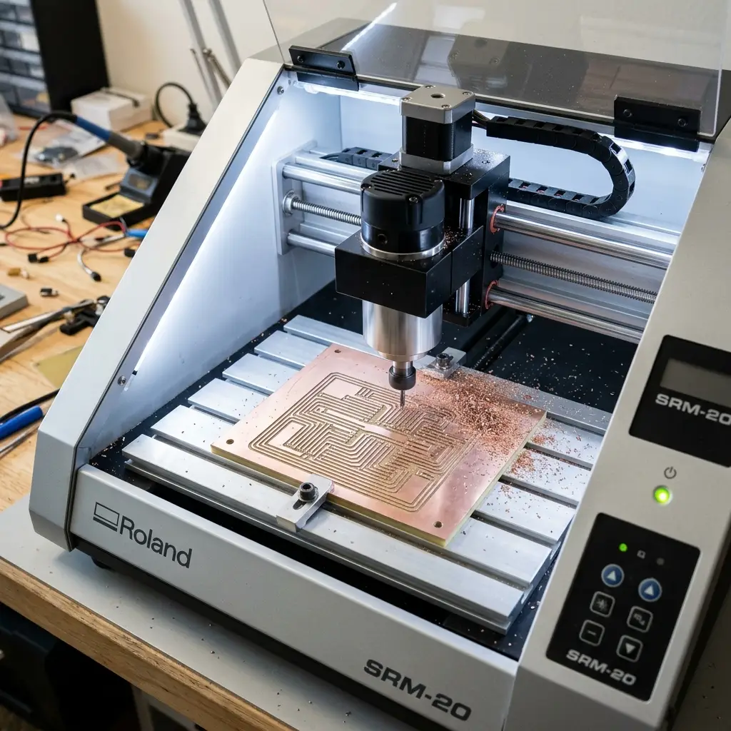
Milling in progress on Roland SRM-20
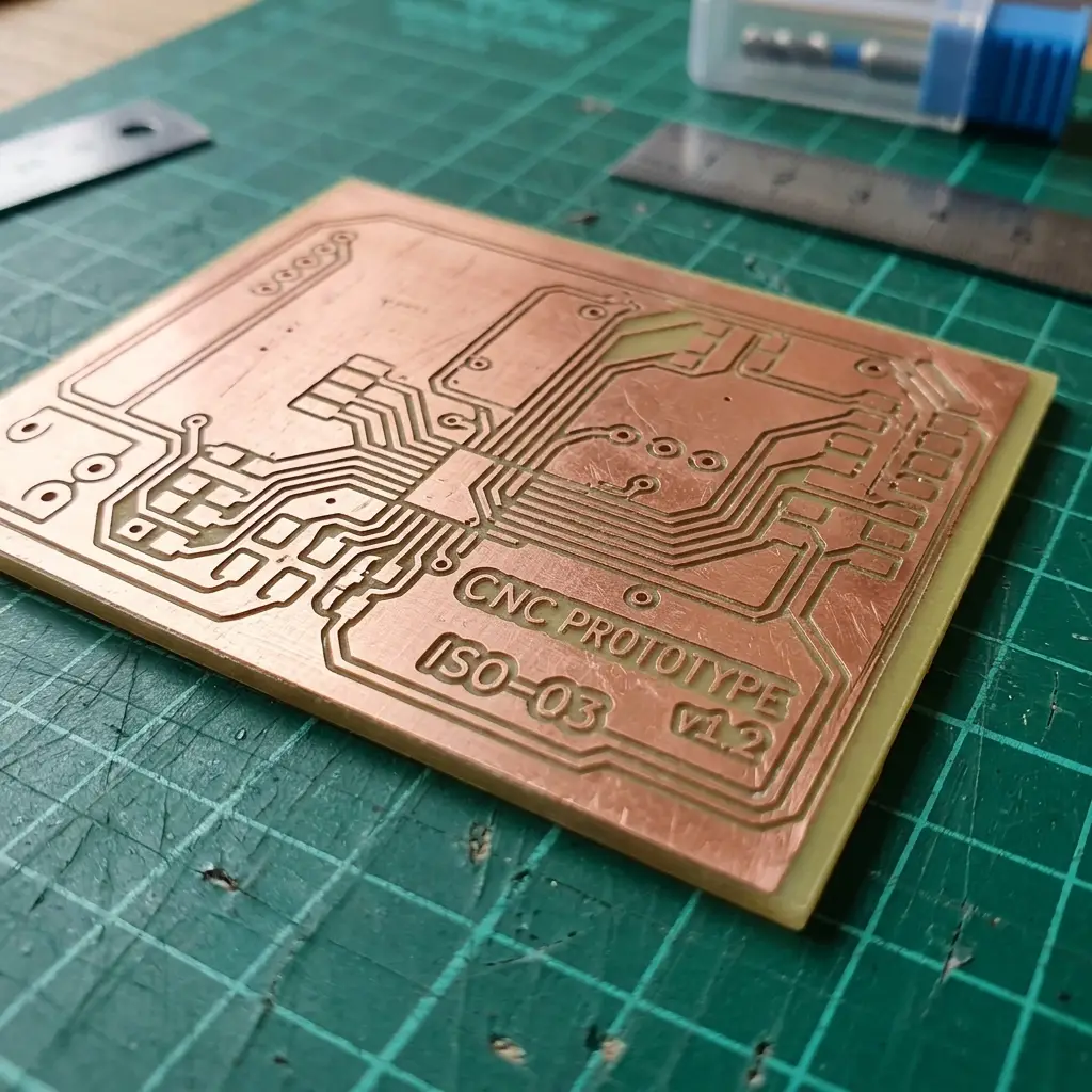
Finished raw milled copper board
Milling Steps:
- Bed Preparation: Cleaned the acrylic sacrificial bed, applied double-sided tape to the back of the FR-4 sheet, and pressed it firmly onto the bed to prevent any vibration.
- Spindle Zeroing: Inserted the 1/64" trace engraving bit. Lowered the Z-axis in VPanel until it was close to the copper surface, loosened the collet set screw, allowed the bit to slide down and touch the copper, and locked it. Set this position as XYZ zero.
- Routing Traces: Sent the trace toolpath file. The machine milled isolation channels around traces.
- Cutting Outline: Swapped the tool to a 1/32" bit, reset Z-zero, loaded the outline toolpath, and cut out the outer frame profile.
Step 2: Soldering & Assembly
I cleaned the copper traces with steel wool to remove oxidation. I then hand-soldered the surface-mount parts using a temperature-controlled iron set to 350°C and lead-free solder wire.
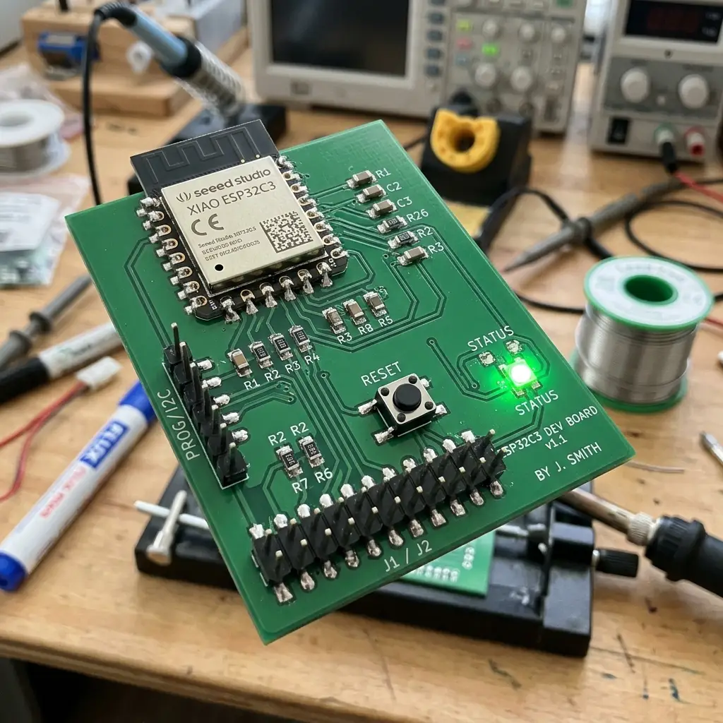
Assembly Workflow:
- Microcontroller: Positioned the Seeed Studio XIAO ESP32-C3 flat on the board and soldered the corner pads first to anchor it.
- SMD Components: Soldered the 1206 resistor, LED, decoupling capacitor, and button switch. I applied solder to one pad first, slid the component into place with tweezers while heating the pad, and then soldered the second pad.
- Connectors: Added the 6-pin male header for programming access.
Step 3: Programming and Hardware Verification
Before plugging the board into USB, I used a digital multimeter set to Continuity Mode to verify that there were no shorts between VCC (3.3V/5V) and GND. I then connected the board using a USB-C cable.
I loaded a test program in Arduino IDE that toggles the status LED when the push button is pressed. The firmware uploaded successfully:
// Board Test Code - Press button to light LED
const int BUTTON_PIN = 3; // GPIO3
const int LED_PIN = 2;    // GPIO2

void setup() {
  pinMode(LED_PIN, OUTPUT);
  pinMode(BUTTON_PIN, INPUT_PULLUP); // Enable internal pull-up resistor
}

void loop() {
  int buttonState = digitalRead(BUTTON_PIN);

  if (buttonState == LOW) { // Button is pressed (pulled to ground)
    digitalWrite(LED_PIN, HIGH); // Turn LED ON
  } else {
    digitalWrite(LED_PIN, LOW);  // Turn LED OFF
  }
}
Original Mill Files
Download the toolpath G-code files generated for the CNC mill:
| File Name | Format | Description | Download Link |
|---|---|---|---|
| traces_1-64.rml | Roland RML G-code (.rml) | Mods toolpath for engraving PCB trace isolation channels. | 📥 Download RML |
| outline_1-32.rml | Roland RML G-code (.rml) | Mods toolpath for cutting board outer boundary edges. | 📥 Download RML |
Have you answered these questions?
- Linked to the group assignment page?
Yes. The link to the group PCB characterization and design rules test is provided in the Group Assignment section. - Documented how you made the toolpath?
Yes. Toolpath generation (isolations using 1/64" endmill at 12000 RPM, and cuts using 1/32" endmill) via FlatCAM is documented in the Step 1: Toolpaths section. - Documented how you made (milled, stuffed, soldered) the board?
Yes. Isolation milling, hole drilling, components stuffing, and soldering of the XIAO ESP32C3 dashboard PCB are documented step-by-step with screenshots and photos in Step 2: Board Fabrication. - Documented that your board is functional?
Yes. Trace continuity and power tests using a digital multimeter, and flashing a basic blink script to test functionality, are documented in Step 3: Verification. - Explained any problems and how you fixed them?
Yes. I documented issues with trace lifting due to feed rates, and how adjusting cutting speeds resolved the problem. - Uploaded your source code?
Yes. The testing source codes are embedded and available in the download table in Original Design Files. - Included a ‘hero shot’ of your board?
Yes. A clear hero shot of the soldered board is included.
Week 8 — Summary
This week focused on hands-on PCB milling and assembly. Here is a summary of the accomplishments:
Mill Configured
Configured Mods CE settings for 1/64" and 1/32" flat endmills on the Roland SRM-20 CNC mill.
PCB Milled
Milled clean isolation tracks and board outlines on FR-4 double/single-sided clad sheets.
Board Assembled
Hand-soldered Seeed Studio XIAO ESP32-C3, SMD components, and terminal headers with lead-free solder.
Firmware Verified
Conducted continuity tests, verified power tracks, flashed test code, and successfully operated input buttons.