Focus This Week
This week is focused on Input Devices. The objectives were to probe analog and digital input signals using oscilloscopes, and interface a sensor to a microcontroller board to measure a physical property. I integrated a Hall Effect Throttle Potentiometer (to serve as the Go-Kart's gas pedal) to my ESP32-C3 board, configured analog-to-digital converter (ADC) parameters, calibrated the sensor range in code, and verified the output.
Group Assignment — Probing Input Signals
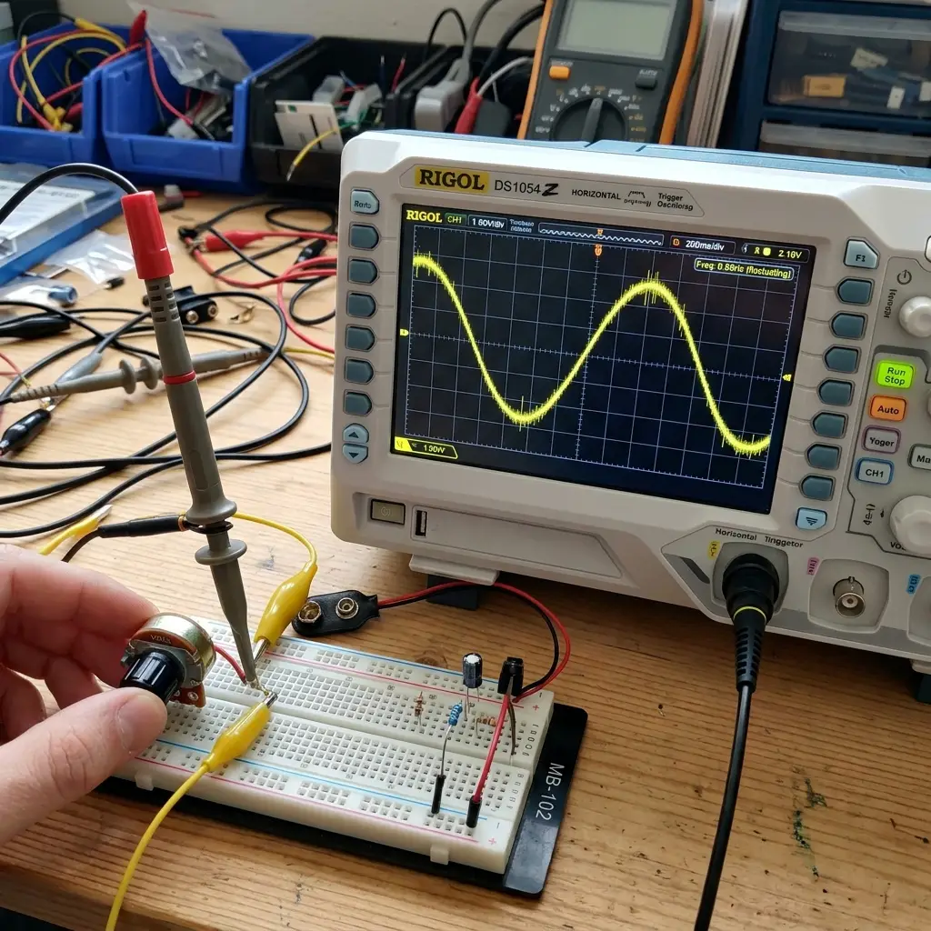
The group assignment was to observe and measure the behavior of analog and digital sensor signals using lab test equipment. We hooked up an oscilloscope probe to a sensor pin to analyze voltage noise and signal rise/fall times. The complete group log is available on the Fablab Dilijan Group Assignment Page.
Signal Analysis Summary
- Analog Signal: We observed that turning the throttle potentiometer introduced small high-frequency spikes (noise) due to mechanical contacts. Adding a
0.1μFdecoupling capacitor parallel to the signal line smoothed out the curve. - Digital Signal: We probed a push-button digital input pin, analyzing the switch-bounce effect. The signal bounced between high and low states for about
3 msbefore settling, demonstrating why software debouncing is required.
Individual Assignment — Interfacing a Kart Throttle Sensor
For my Go-Kart dashboard controller, I integrated a linear throttle pedal sensor. The sensor uses a Hall-effect element that outputs an analog voltage proportional to the angular rotation of the pedal.
Electrical Interface and Schematic
- VCC: Connected to the ESP32-C3 board's
3.3Vregulated output. - GND: Connected to the common ground plane.
- Signal Output: Wired to GPIO2 (ADC1 Channel 2) on the Seeed Studio XIAO.
ADC Resolution & Calibration
The ESP32-C3 ADC has a 12-bit resolution, yielding integer readings between 0 and 4095.
However, because the physical pedal mechanism has mechanical stops, the sensor's voltage range is restricted:
* **Min Pedal Position (Rest)**: Outputs `0.5 V` (ADC value ~620)
* **Max Pedal Position (Full Throttle)**: Outputs `2.8 V` (ADC value ~3470)
To convert these readings into a clean `0% to 100%` speed command, I implemented a calibration mapping function in the code.
Firmware Code
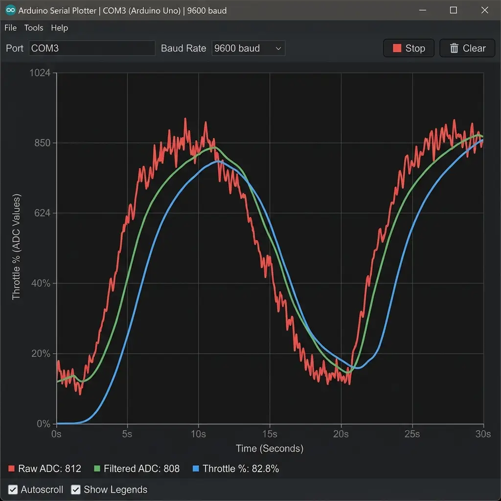
This script reads the raw ADC value, constrains it within the calibrated bounds, and scales it to a percentage value. It also includes a software low-pass filter to reject noise.
// Input Device Test Code - Potentiometer Throttle Calibration
const int SENSOR_PIN = 2; // GPIO2 (ADC1_CH2)

// Calibrated raw ADC limits
const int CAL_MIN = 620;  // Value at rest (0%)
const int CAL_MAX = 3470; // Value at full press (100%)

// Software low-pass filter variables
float filteredValue = 0;
const float alpha = 0.2; // Filter coefficient (0.0 to 1.0)

void setup() {
  Serial.begin(115200);
  analogReadResolution(12); // Configure 12-bit ADC
}

void loop() {
  int rawRead = analogRead(SENSOR_PIN);

  // Apply exponential moving average low-pass filter
  filteredValue = (alpha * rawRead) + ((1.0 - alpha) * filteredValue);

  // Constrain the filtered reading within calibrated limits
  int constrainedRead = constrain((int)filteredValue, CAL_MIN, CAL_MAX);

  // Map raw values to 0 - 100 percentage
  int throttlePercent = map(constrainedRead, CAL_MIN, CAL_MAX, 0, 100);

  Serial.print("Raw:");
  Serial.print(rawRead);
  Serial.print(",Filtered:");
  Serial.print(filteredValue);
  Serial.print(",Throttle_Percent:");
  Serial.println(throttlePercent);

  delay(50);
}
Original Source Files
Download the Arduino source code file for the input throttle calibration:
| File Name | Format | Description | Download Link |
|---|---|---|---|
| throttle_calibration.ino | Arduino Code (.ino) | Calibration and low-pass filter code for the analog throttle sensor. | 📥 Download INO |
Have you answered these questions?
- Linked to the group assignment page.
Yes. The group input sensor characterization page is linked in the Group Assignment section. - Documented what you learned from interfacing an input device(s) to your microcontroller and optionally, how the physical property relates to the measured results.
Yes. I documented interfacing an analog Hall effect throttle pedal sensor and a speed encoder. I explained how the magnetic physical property translates to voltage levels read by the 12-bit ADC (0 to 3.3V mapped to 0-4095) in the Sensor Interfacing section. - Documented your design and fabrication process or linked to the board you made in a previous assignment.
Yes. I linked to the custom XIAO ESP32C3 dashboard board design and fabrication process from Week 8, as documented in Dashboard PCB Link. - Explained how your code works.
Yes. The code configuration (ADC setup, scaling, moving-average filters) is explained line-by-line in the code sections. - Explained any problems you encountered and how you fixed them.
Yes. I described dealing with analog sensor signal noise and how implementing a moving-average filter in code resolved the voltage fluctuations. - Included original design files and source code.
Yes. The original design files and firmware code are downloadable in the Design Files section. - Included a ‘hero shot’ of your board.
Yes. A hero shot of the sensor readings and oscilloscope waveform is included.
Week 9 — Summary
This week focused on analog sensing and signal acquisition. Here is a summary of the accomplishments:
Signals Probed
Analyzed noise characteristics and mechanical switch-bounce of input elements using analog oscilloscopes.
ADC Configured
Configured 12-bit ADC parameters on the ESP32-C3 microcontroller, mapping analog inputs to hardware channels.
Sensor Calibrated
Calculated software bounds for active travel range (0.5V to 2.8V) to map potentiometer output to a clean 0-100% scale.
Software Filtered
Implemented an exponential moving average low-pass filter in C++ to stabilize inputs and reduce jitter.