Week 8 Electronics Production
Group assignment
Week 8 Chaihuo group assignment.
Small CNC — Cutting PCB
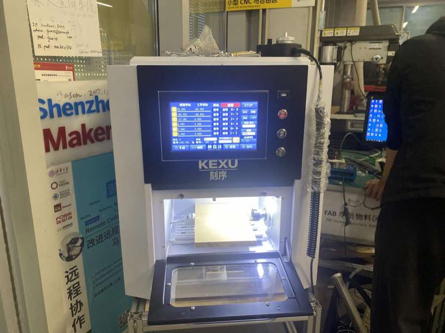
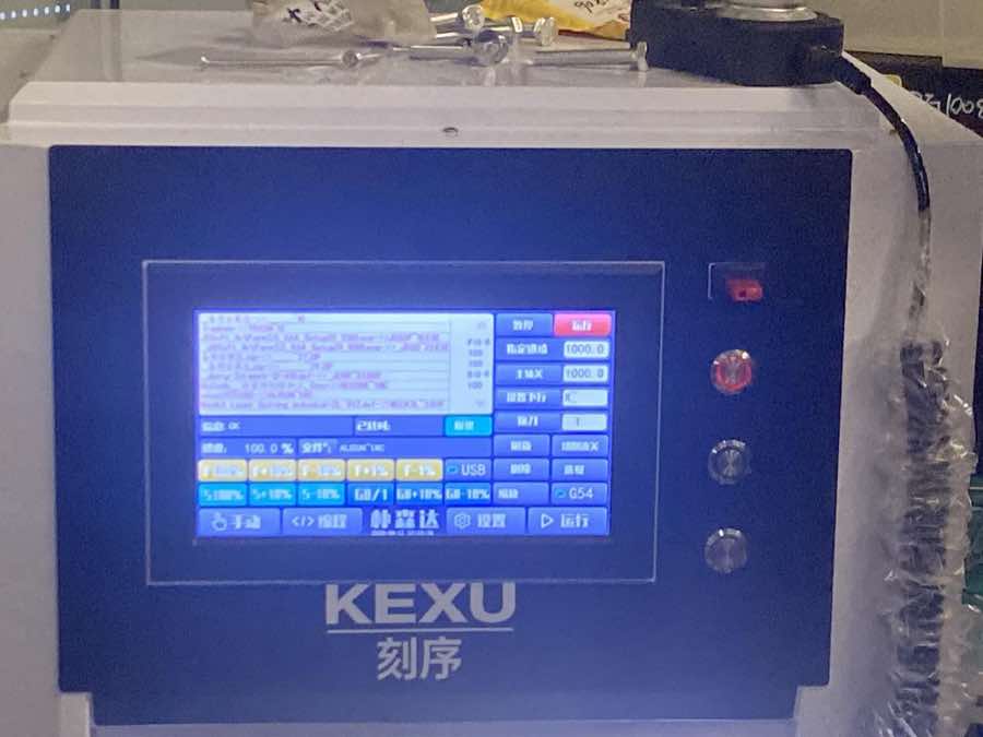
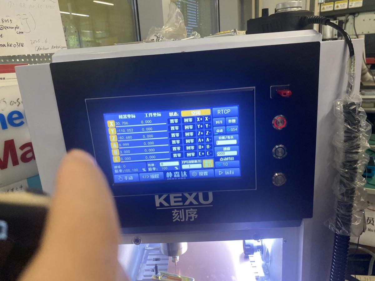
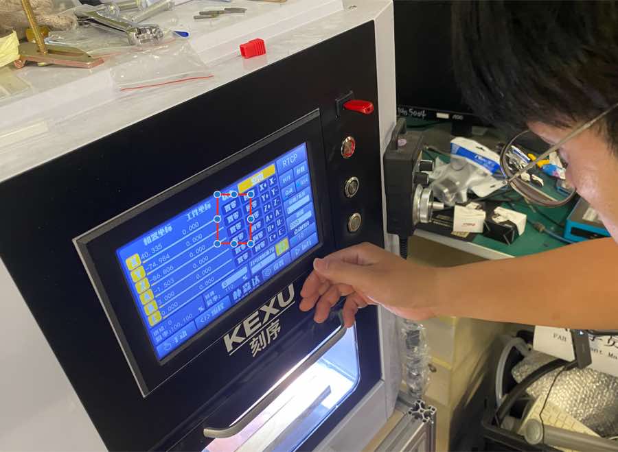
Step 1 Turn on the machine
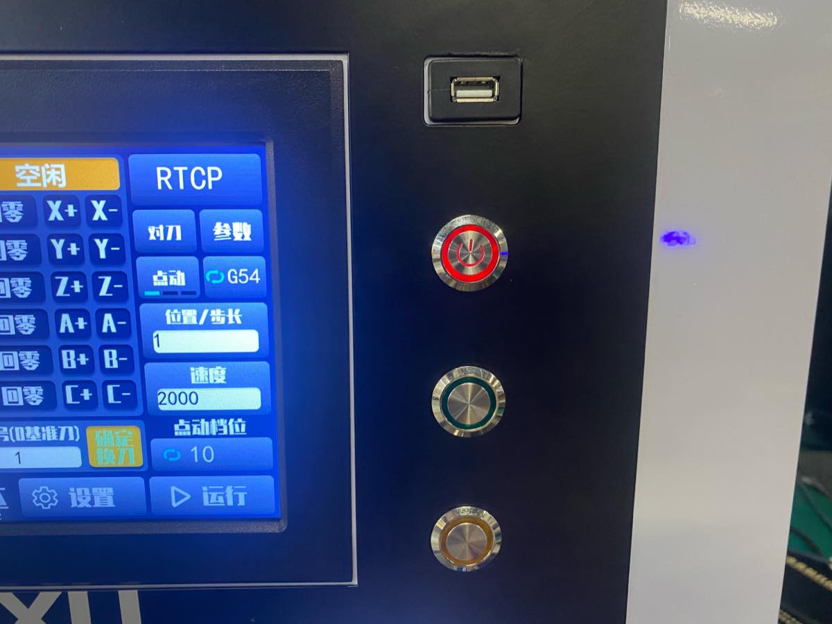
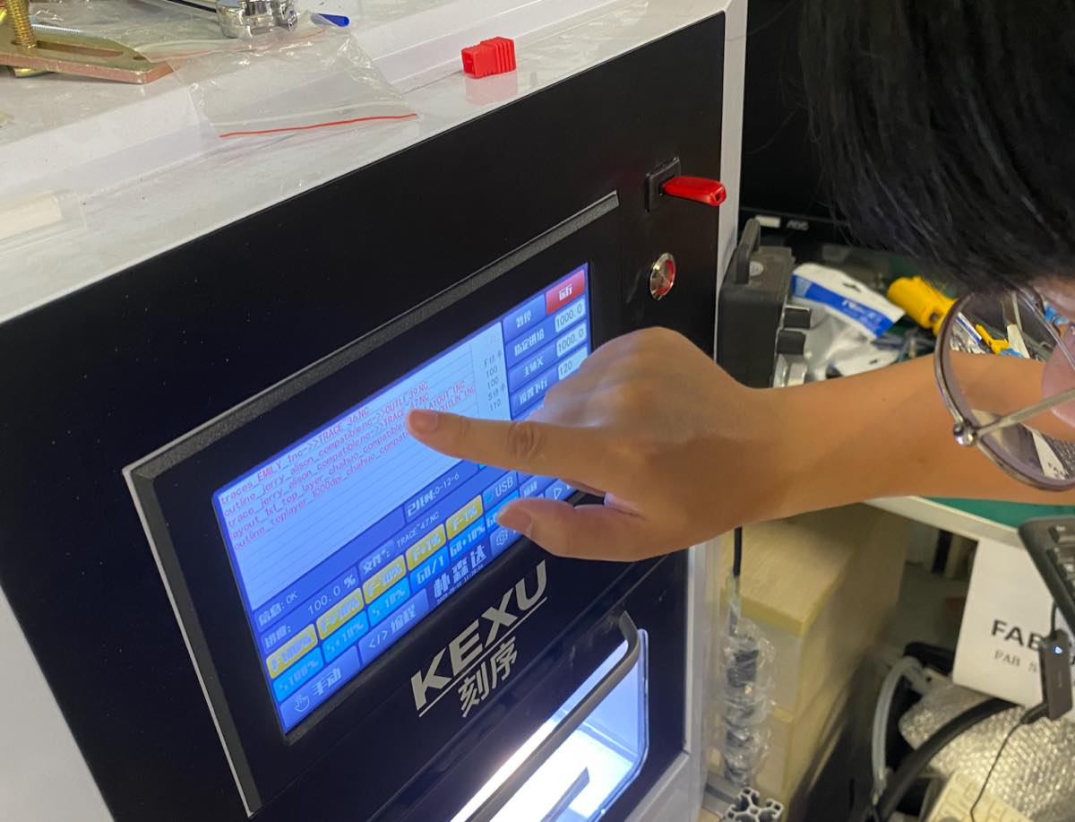
Step 2 Choose the file, all operation is on the panel, no need for another PC, USB flash drive can be inserted into the machine directly.
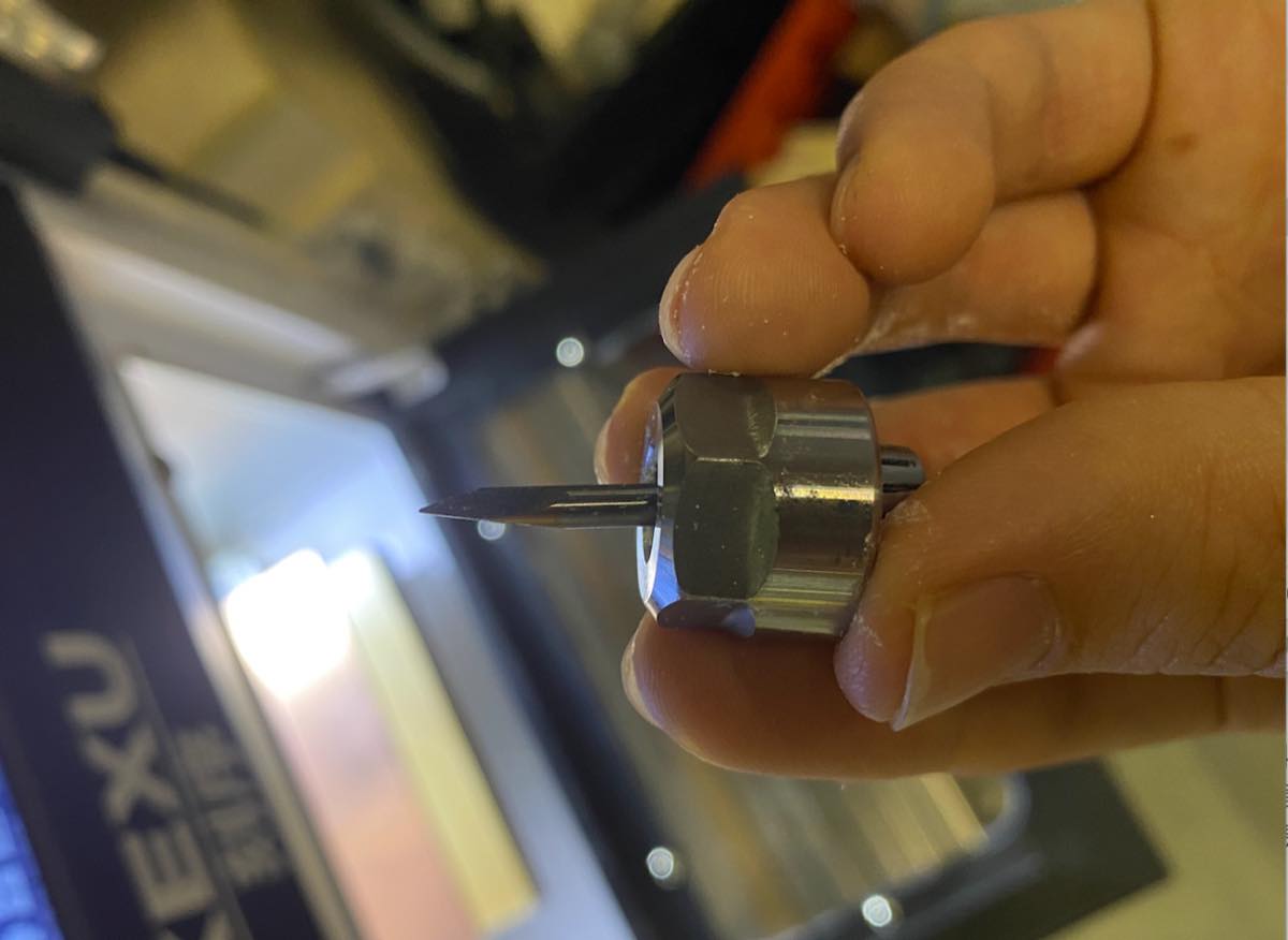
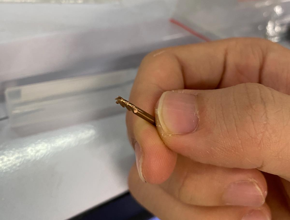
Step 3 Assemble the cutter. Introduced two cutters, one is for circuit, another is for cutting the board
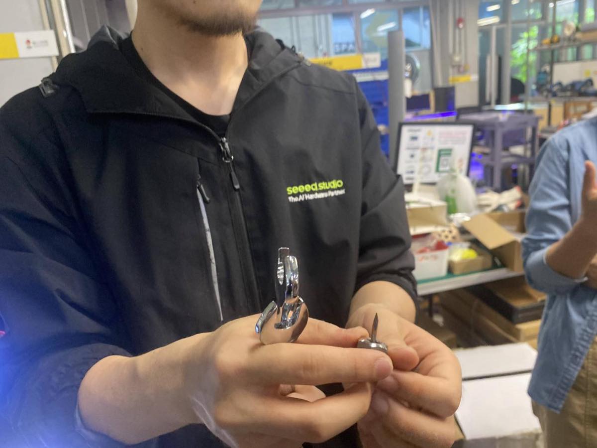
Assembling the cutter
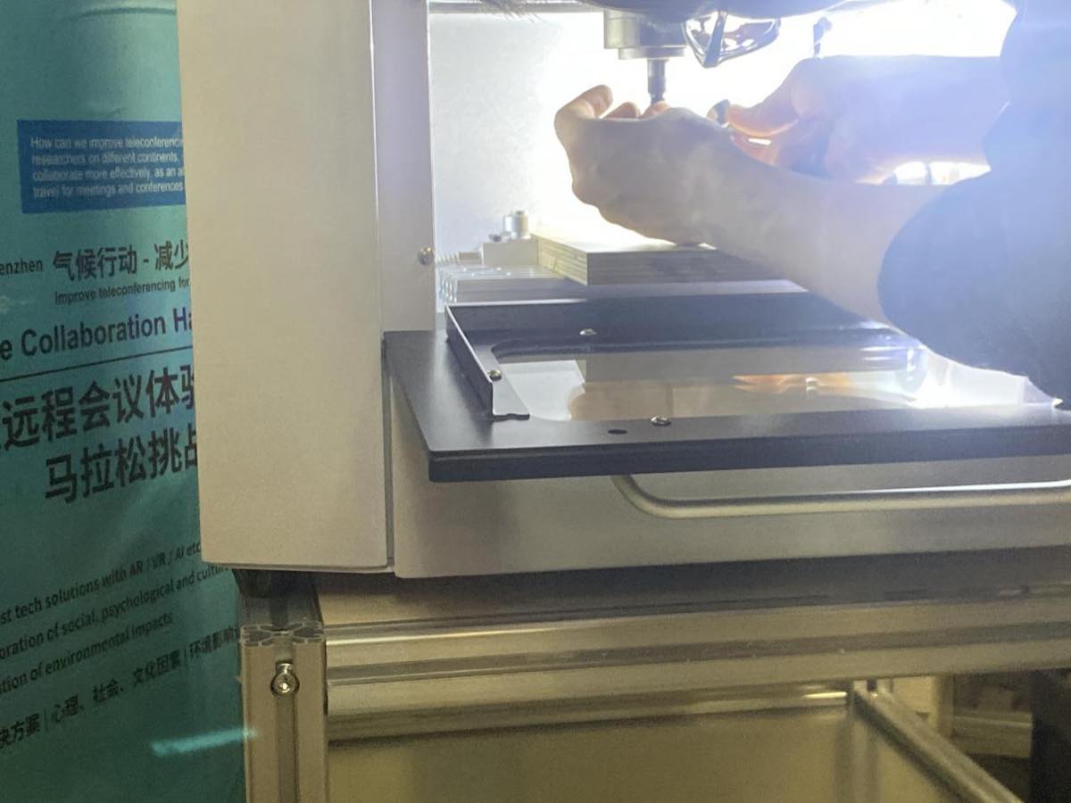
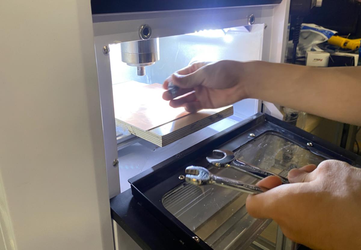
Step 4 Place the copper board and fix it on the platform
Step 5 Find the zero point
Select a point close to the edge as the zero point and then “setting zero” (置零)
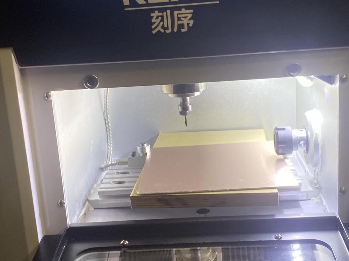
Step 6 Start cutting
JLC PCB
https://www.jlc.com/?from=PZ-pLpu&s=JC, register and login
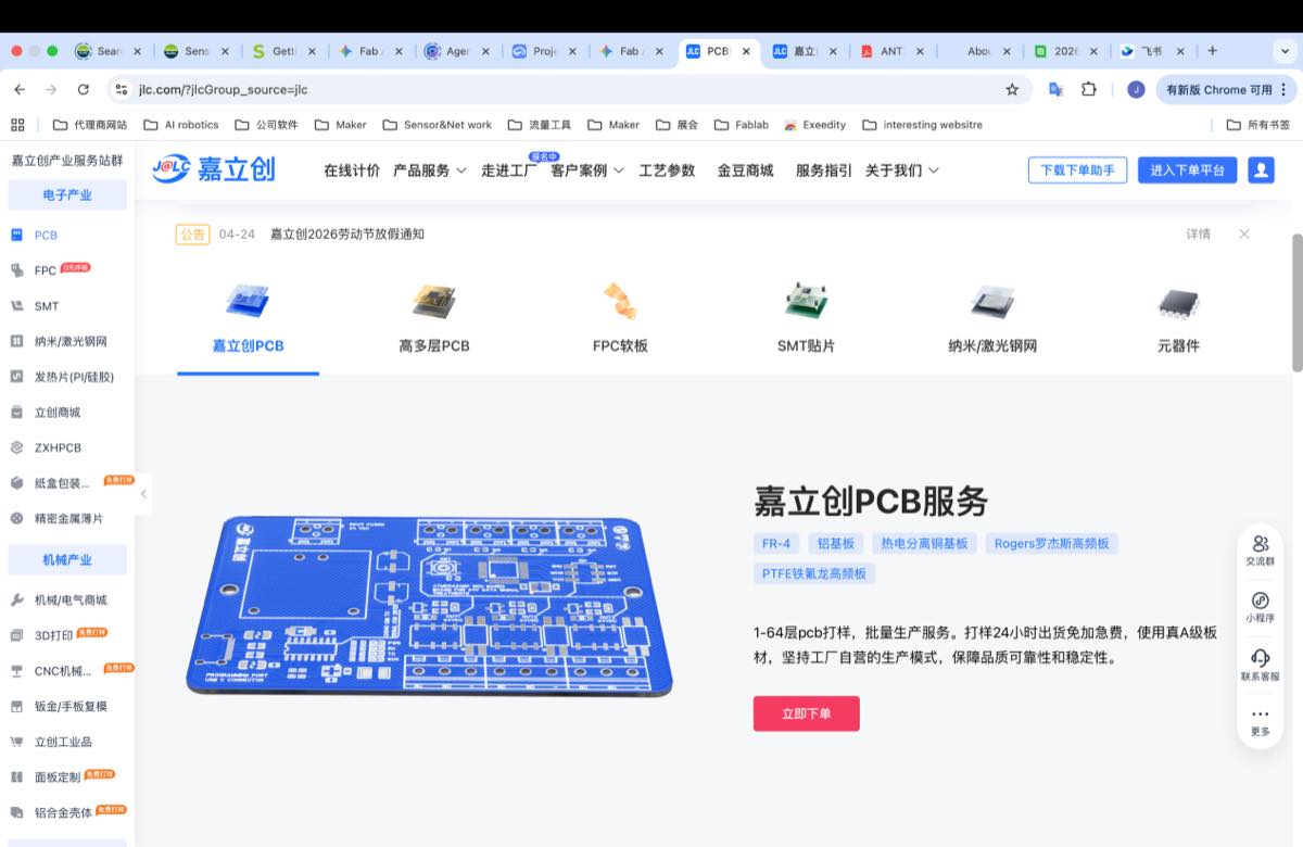
Fill the information below,
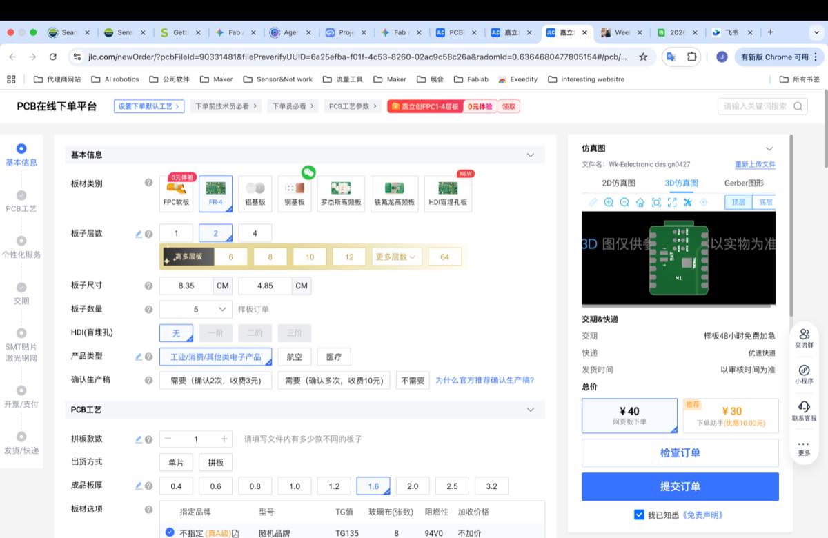
Submit the order and wait for the approval of the order.
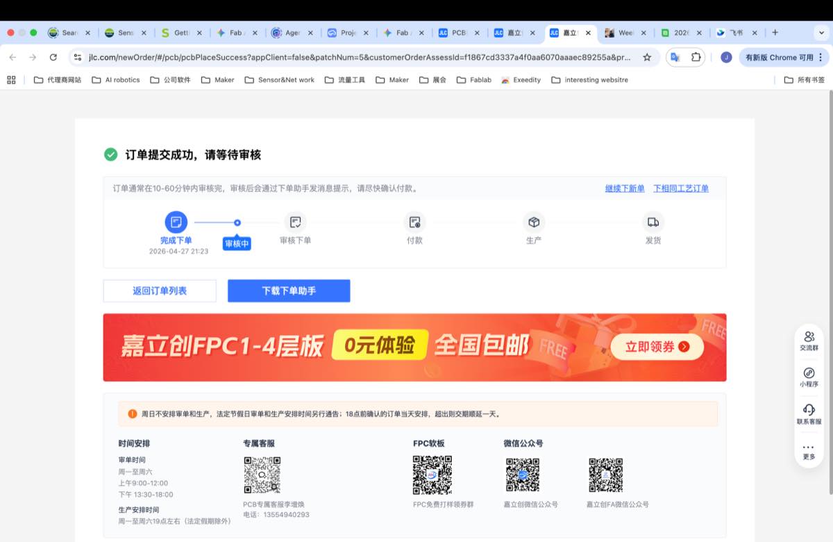
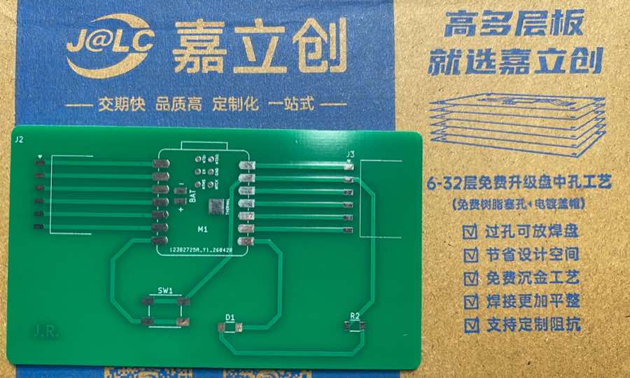
Finally, I got the PCBA from JLC
PCB small CNC
Transfer the Gerber to G-code
Step 1. The Gerber files have been created in Week 6, I will use them directly.
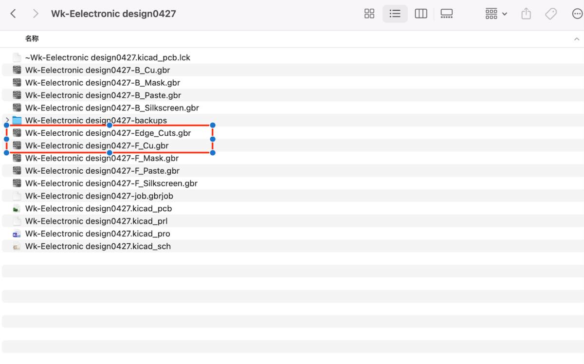
Step 2. Transfer the Gerber file to convert to png files from an online tool, Gerber2PNG
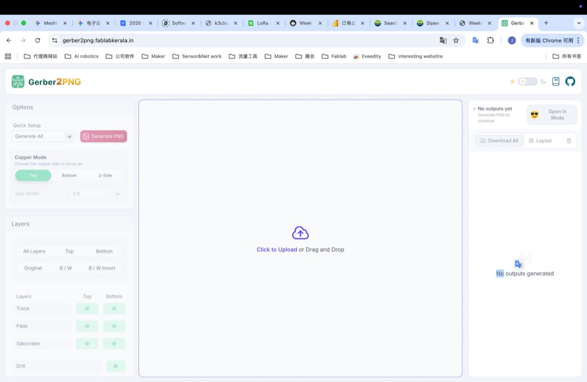
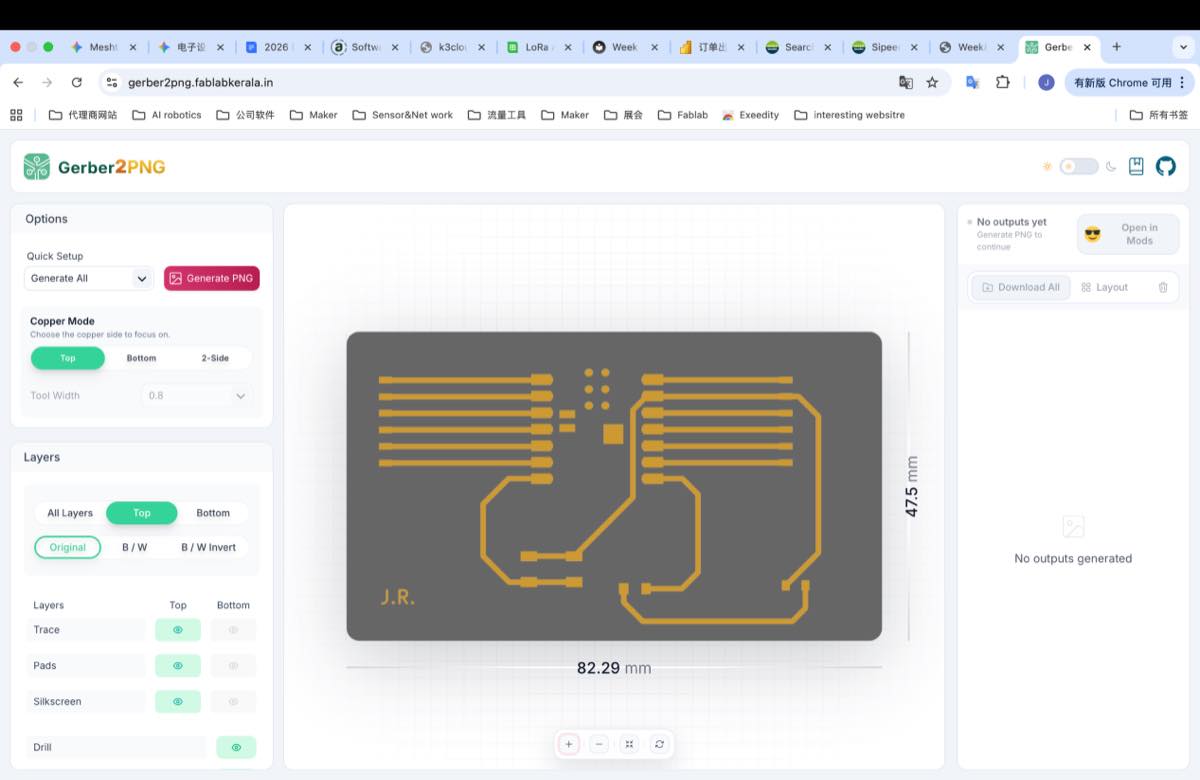
Upload the two files above, I got the image below
Click the button in red above “Generate PNG”, and then on the right side, you will see three files, download the Outline.png and traces.png.
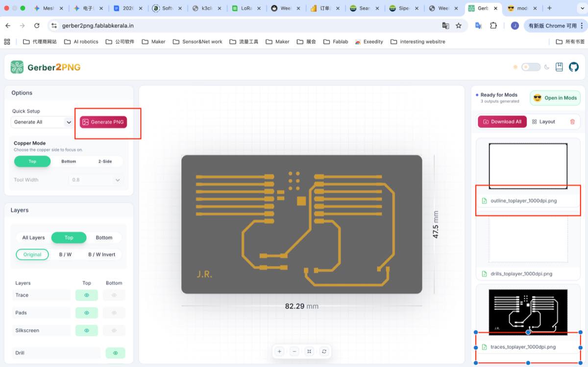
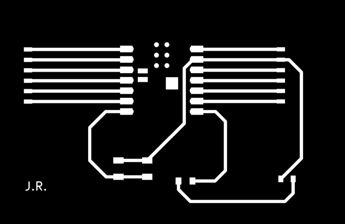
traces.png (representing the circuit)
outline.png (representing the board boundary)

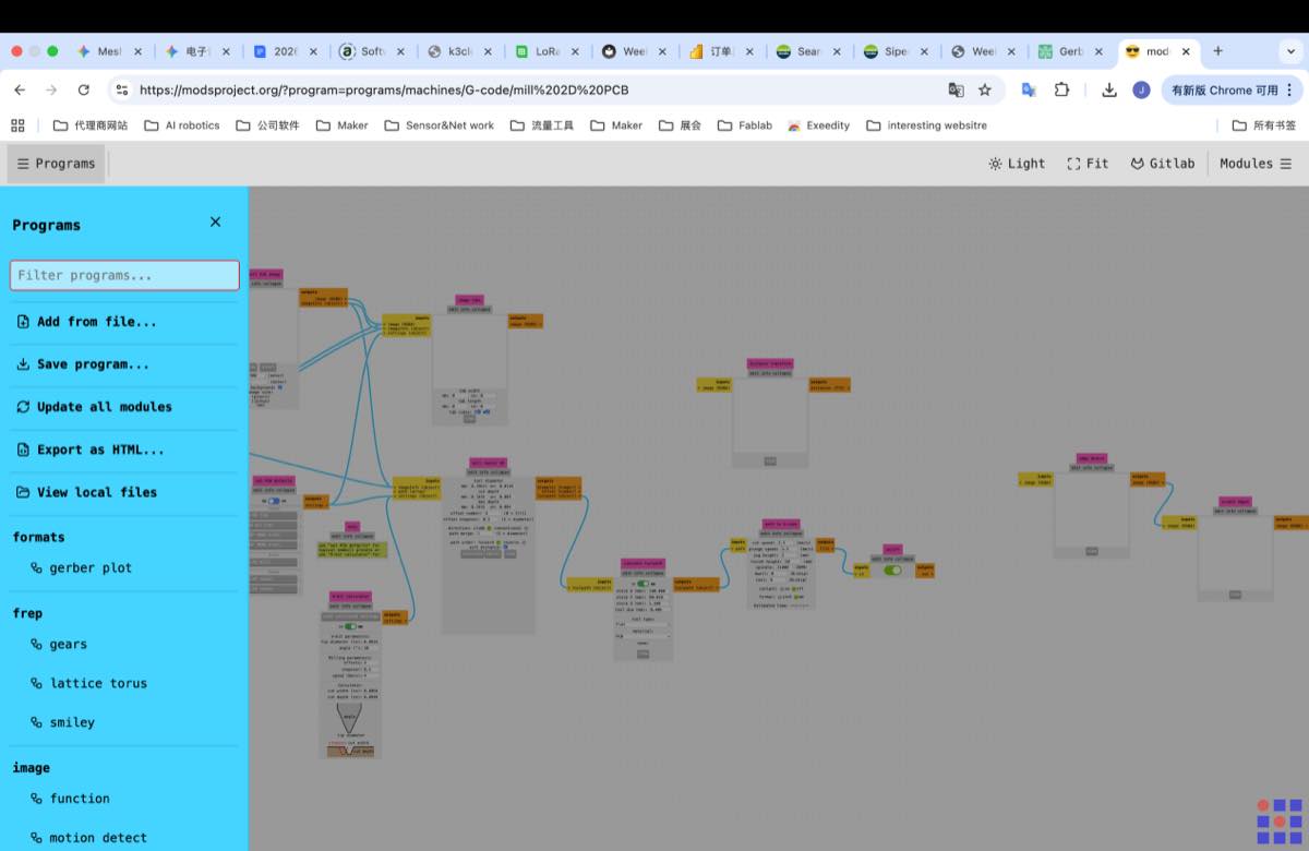
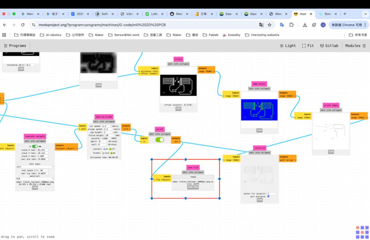
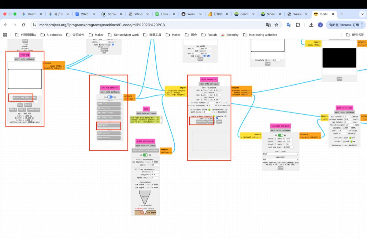
Step 3 Converting the PNG to the G-code with online tool, MODS project
3.1 Upload the Trace.png, use the module below to upload the Trace.png file, select 40° #502 V-bit, stepover 0.8, then click Calculate
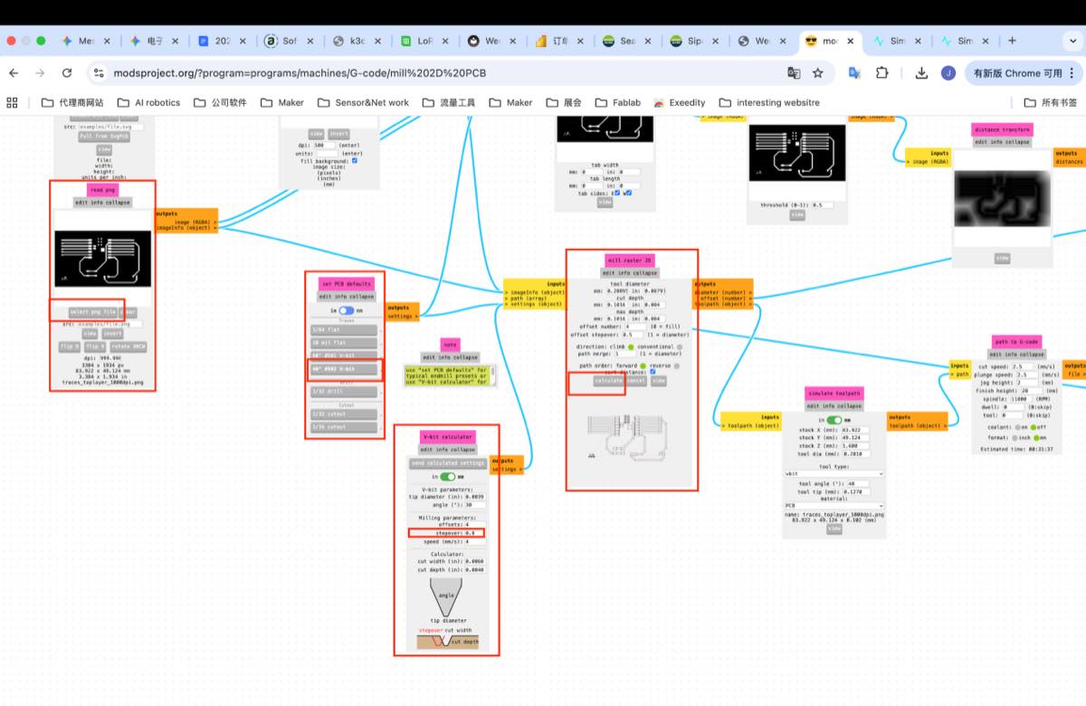
Got a simulation image as below
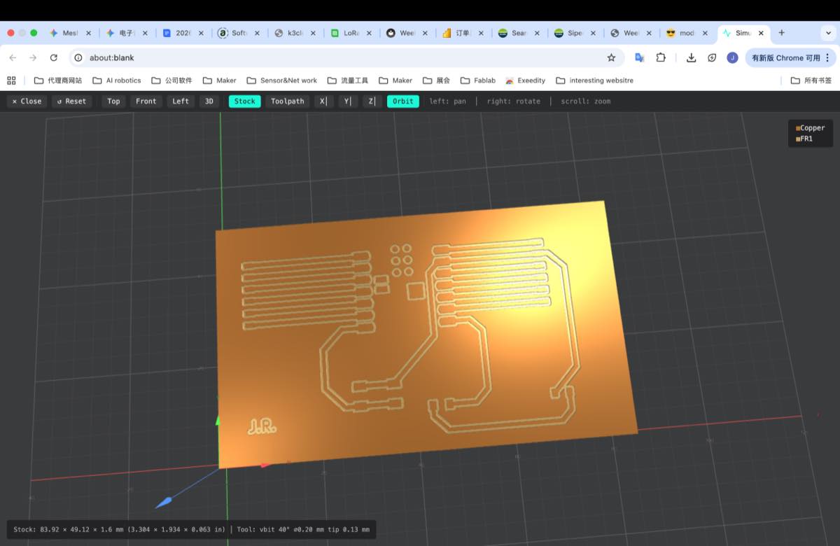
Save the file
3.2 Upload the outline.png, upload the picture, select 1/32 drill, click “Calculate”, and then save, similar to above.
Two G-code files
Step 4. Use the small CNC to cut the PCB
4.1 Copy the two G-code files to USB drive and insert the drive to the small CNC machine
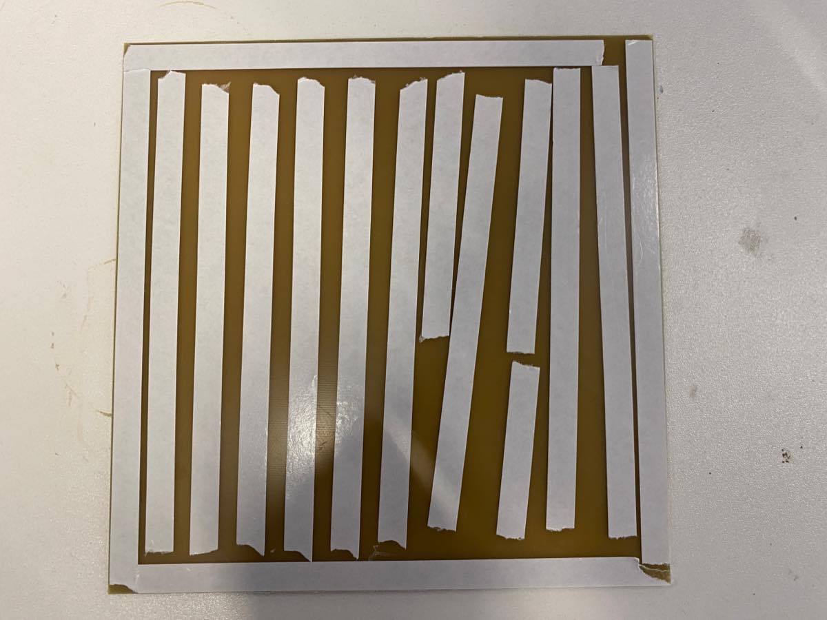
4.2 Fix the Copper plate on the platform with 2-side adhesive tape. For tape, make sure, there is no crossing, so that the copper plate will be placed flat.
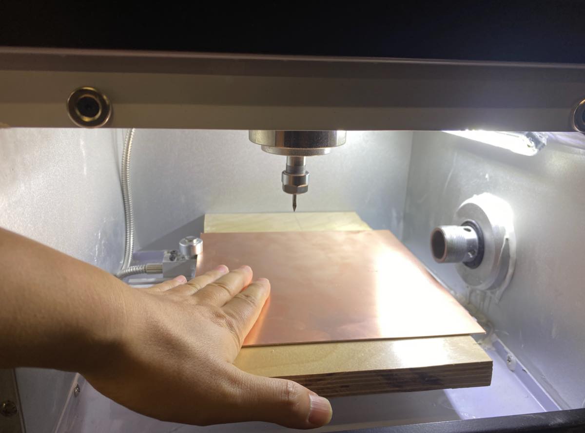
4.3 Check the drill if it needs to be replaced or not, and tighten it again.
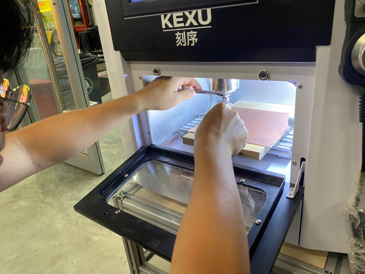
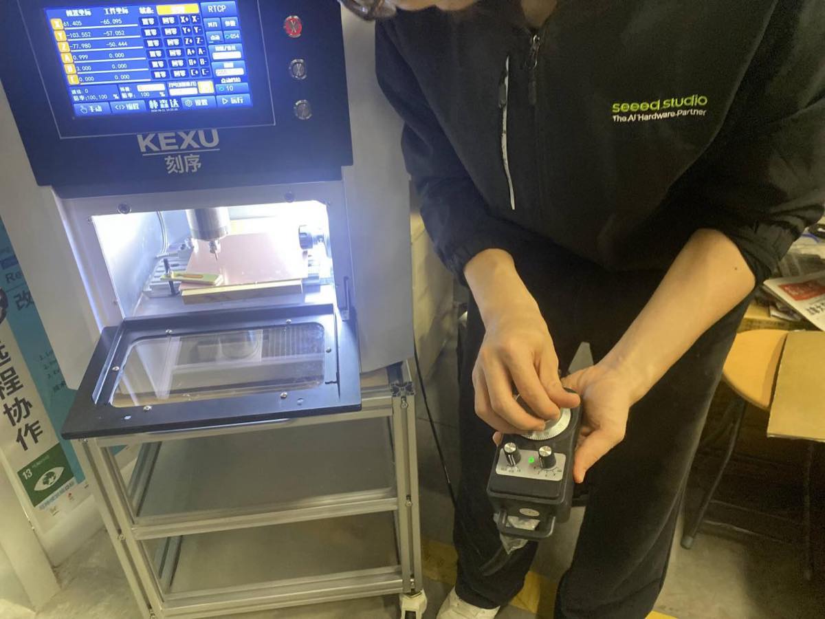
4.4 Use the controller to set the Zero point of X, Y, Z. the peak of drill could touch the surface slightly.
4.5 Set the zero point on the machine
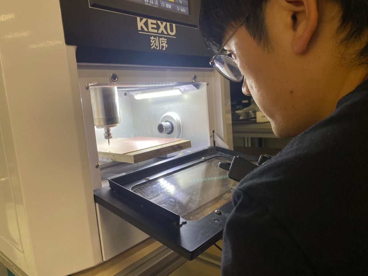
4.6 Find the Trace.nc file and start cutting
4.7 The small CNC machine is working, see the video
4.8 For outside.nc, we need to change to another drill, and repeat again to cut the edge of the PCB.
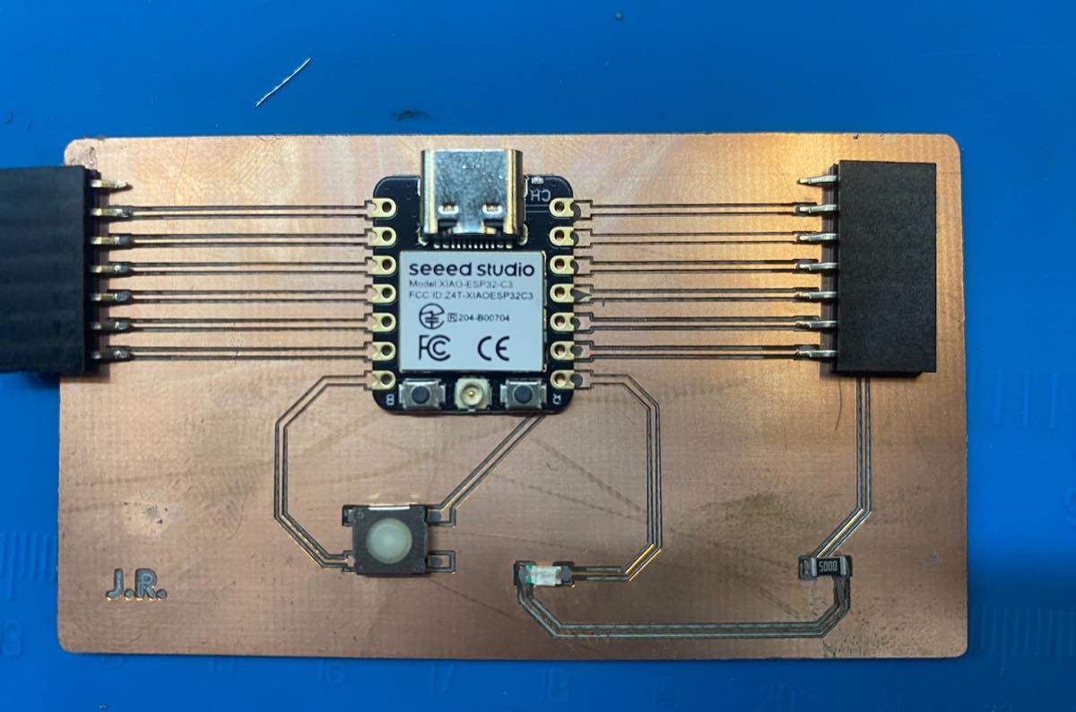
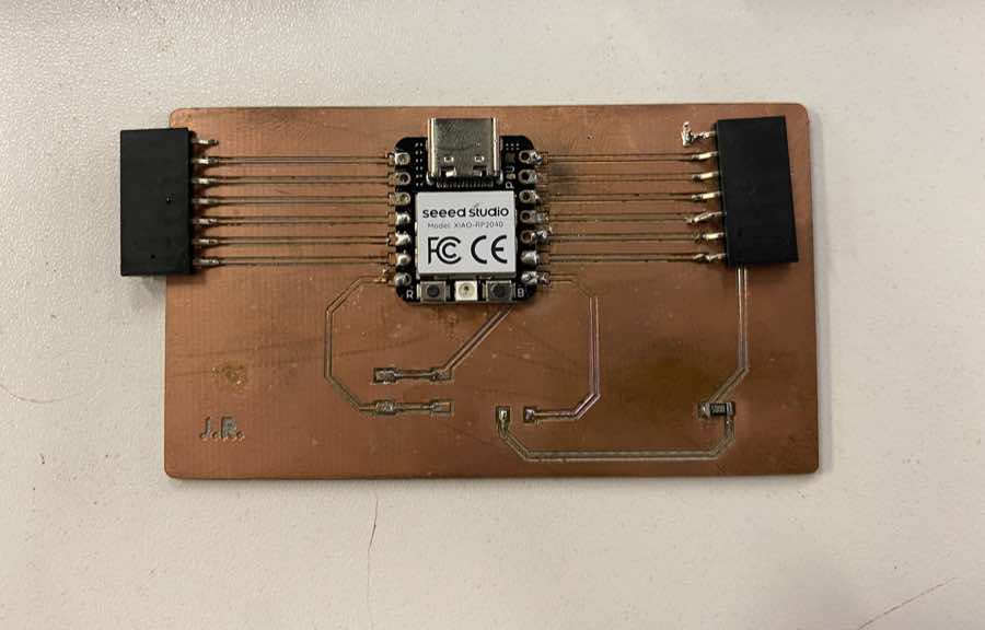
Finally, I got my first PCB by Small CNC.
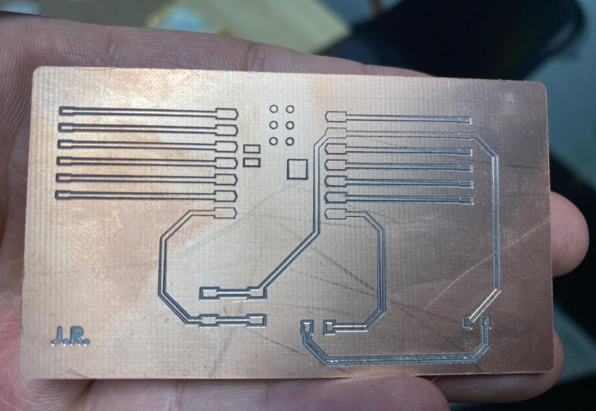
The board looks good, with a simple check using a multimeter, 1) each part of the circuit is connected 2) each part of the circuit is not connected with other parts.
Update on 28th, Jun.
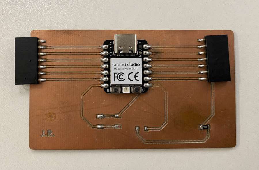
Add XIAO and connector on the board
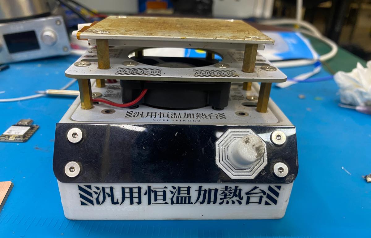
I will use the platform for soldering with solder paste with a melting point of 183°C.
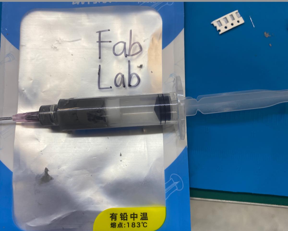
Add the solder paste to the points. Control the volume — just a little bit — and then place the components.
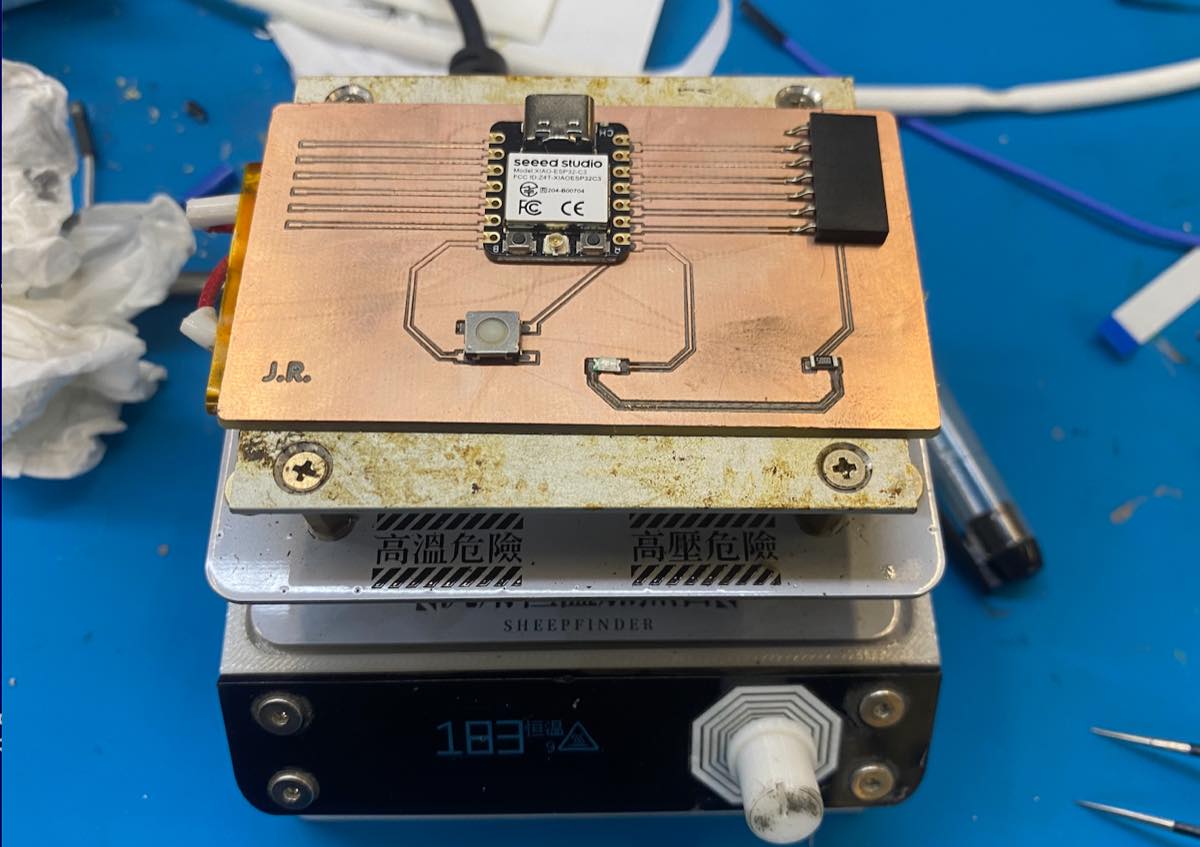
It did not look good, so I used solder wire to strengthen the connections.
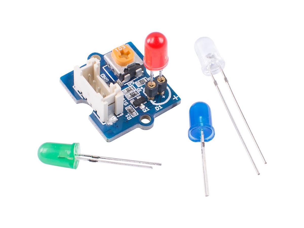
Testing with a Grove LED indicator module
I used a cable to connect them. The wiring is as below.
As pictured:
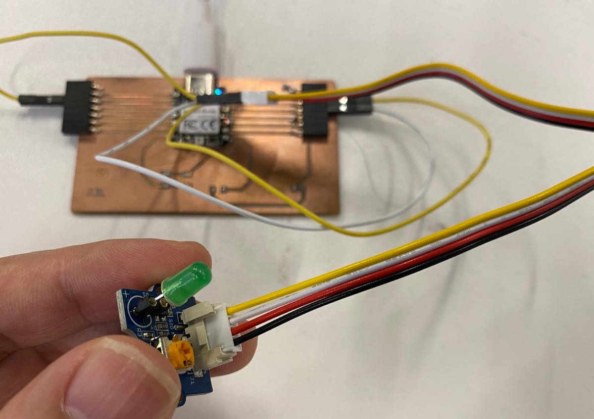
Cursor provided the code below:
const int LED_PIN = D1;
const int BLINK_MS = 500;

void setup() {
  pinMode(LED_PIN, OUTPUT);
}

void loop() {
  digitalWrite(LED_PIN, HIGH);
  delay(BLINK_MS);
  digitalWrite(LED_PIN, LOW);
  delay(BLINK_MS);
}
As video below: