Final project
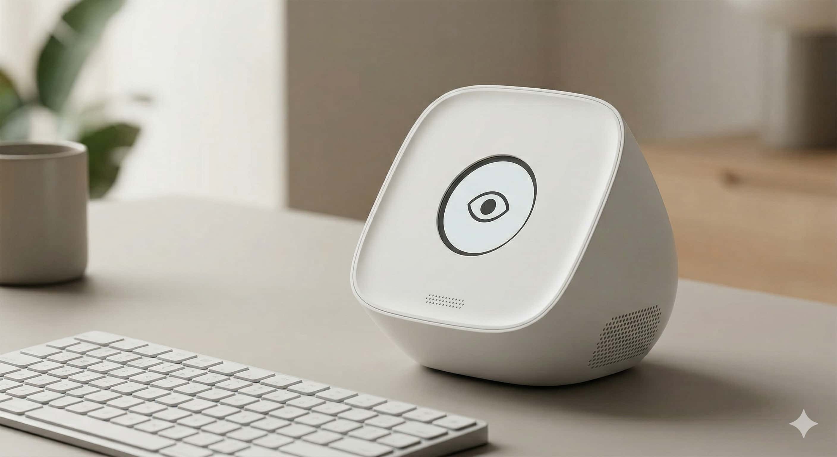
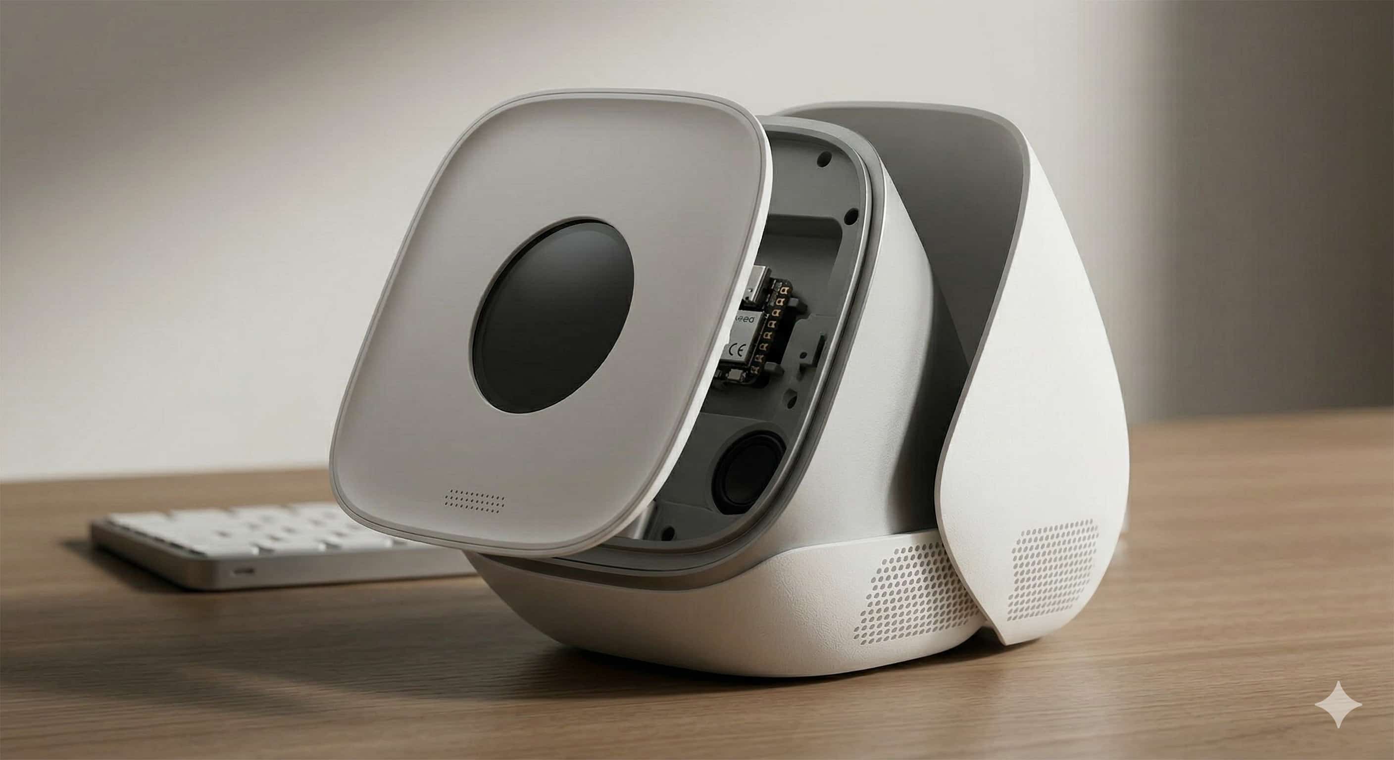
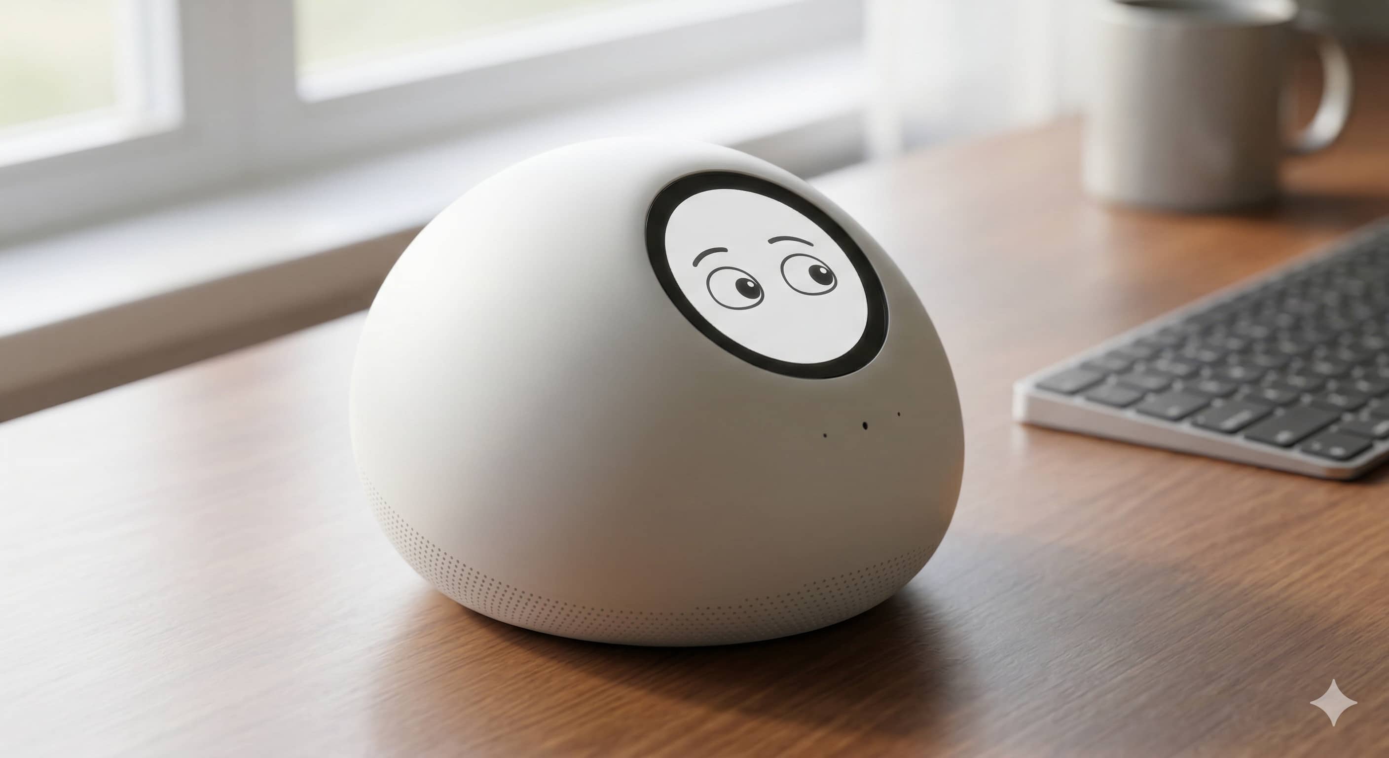
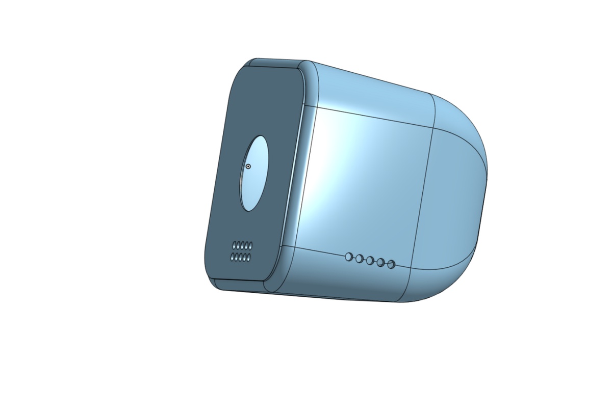
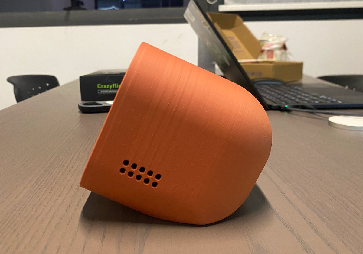
Desktop AI companion device with voice interaction — working name Lucky Bot.
Concept images (Gemini)
Timeline
Final project - Lucky Bot
| Date | Work | Remark |
|---|---|---|
| 9th,May | Finalize the idea Material for final, get the dimension of display | Material: Xiao, Display, mic |
| 10th, May | Finish the 3D design and 3D printing | How to add the 2D design? |
| 11th-12th,May | Build the prototype | |
| 13th, 14th,May | ||
| 15th,May | Receive the PCB and solder the component, make the prototype |
9th, May
Finalize the idea,
I wouldn’t change the ID of AI bot, I will try to make the 3D first
Components:
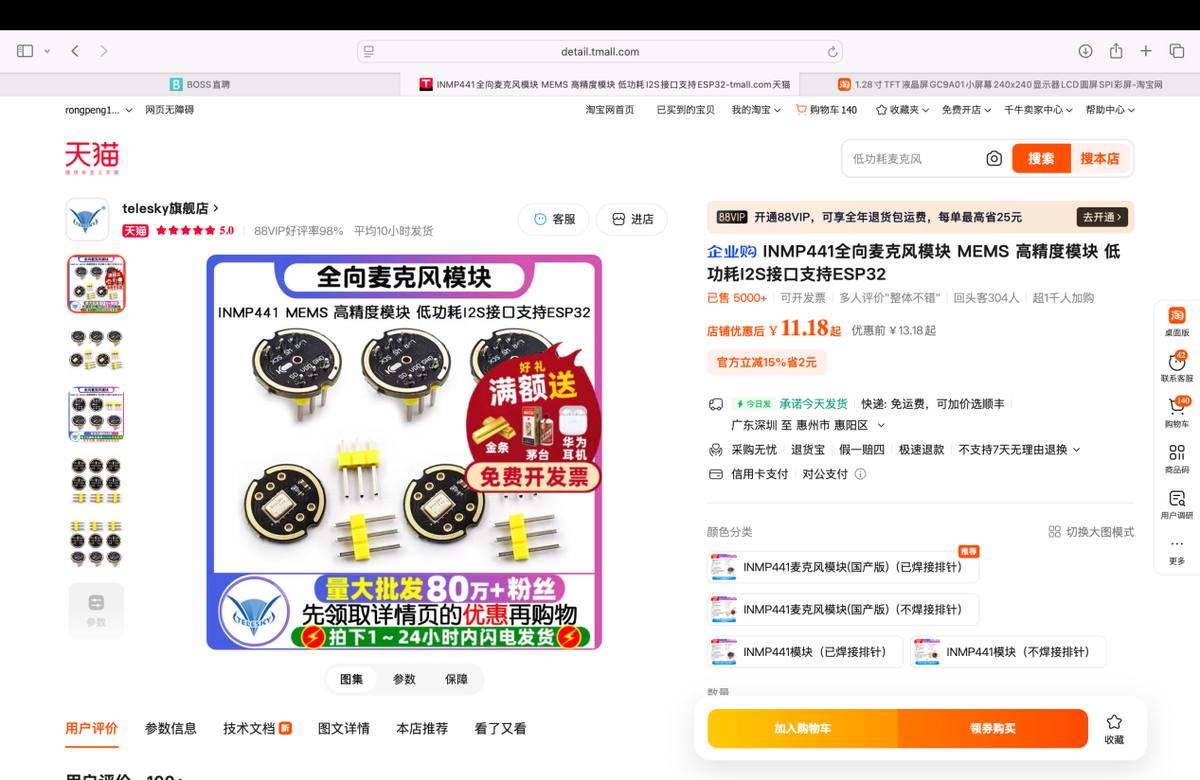
Input: microphone,INMP441
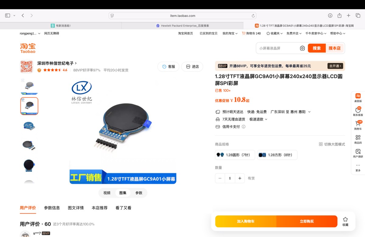
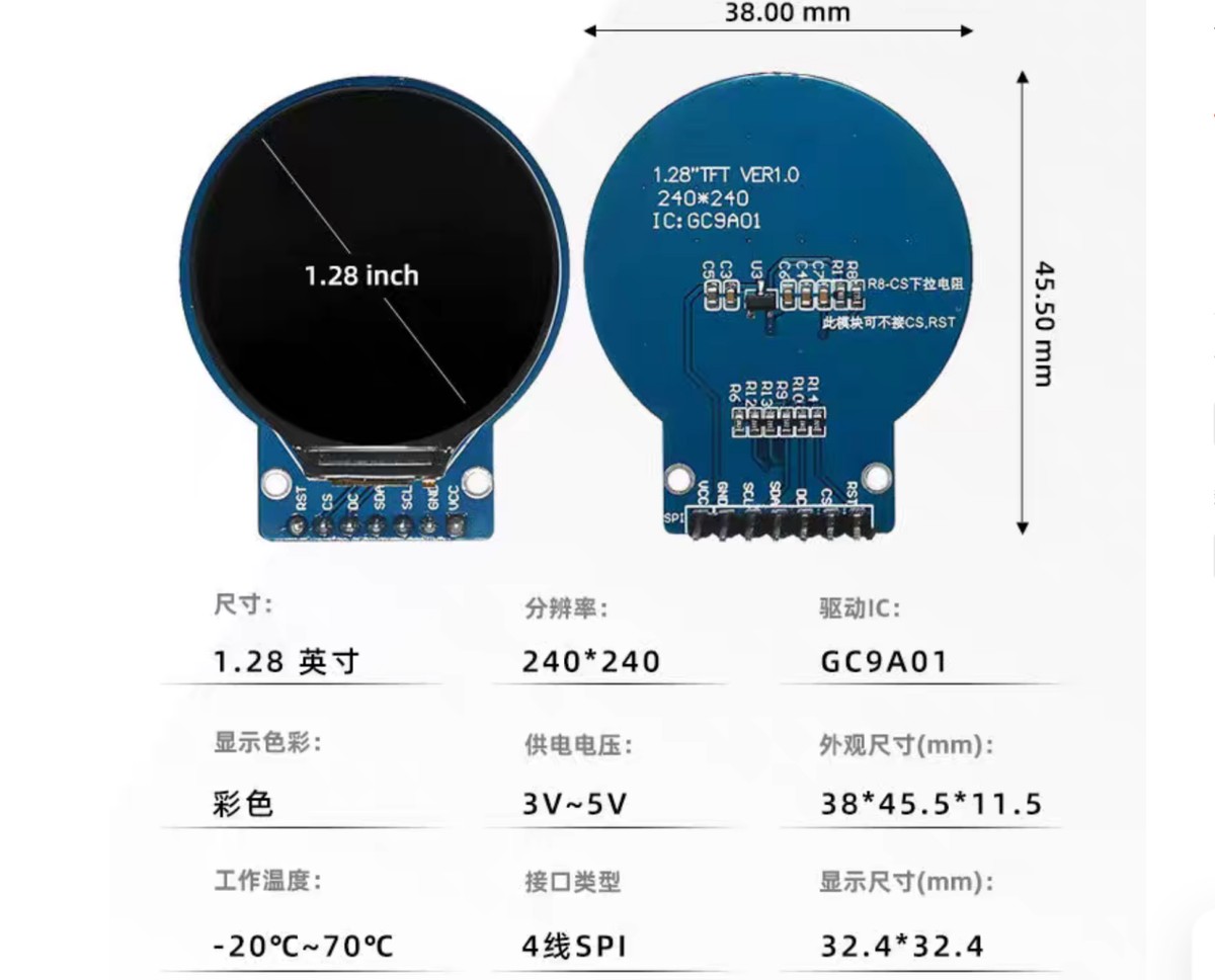
Output: display,GC9A01 1.28 inch, LCD,SPI display
MCU: Xiao ESP32-C3
PCB made before
Firmware: LLM
The material of the final
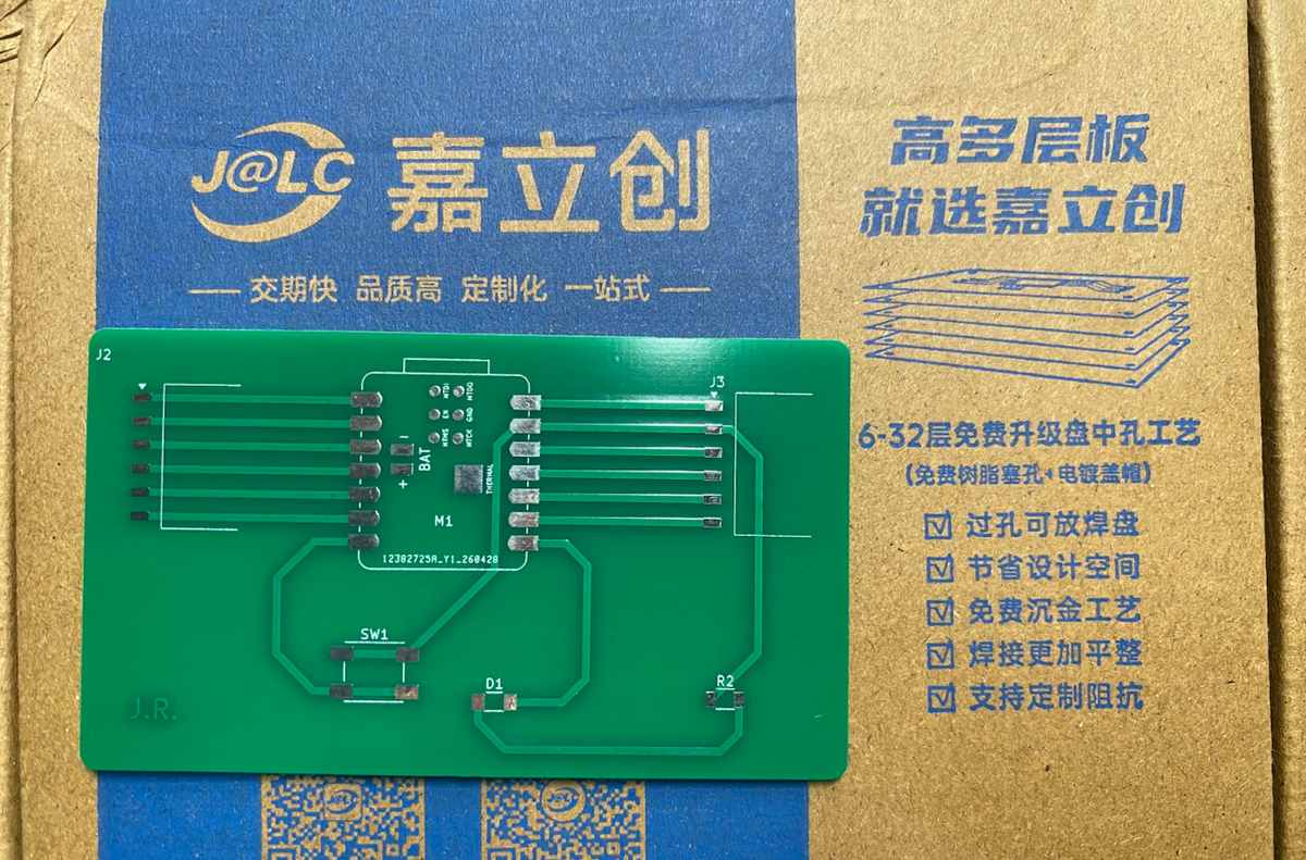
PCB already got produced by JLC.
Mic, INMP441 purchased from Taobao
Display: GC9A01 1.28 inch, recommend by Gemini, purchased from Taobao
10th, May
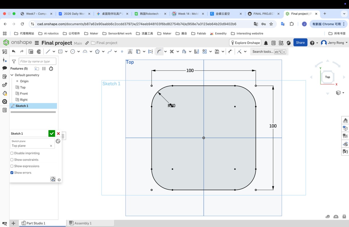
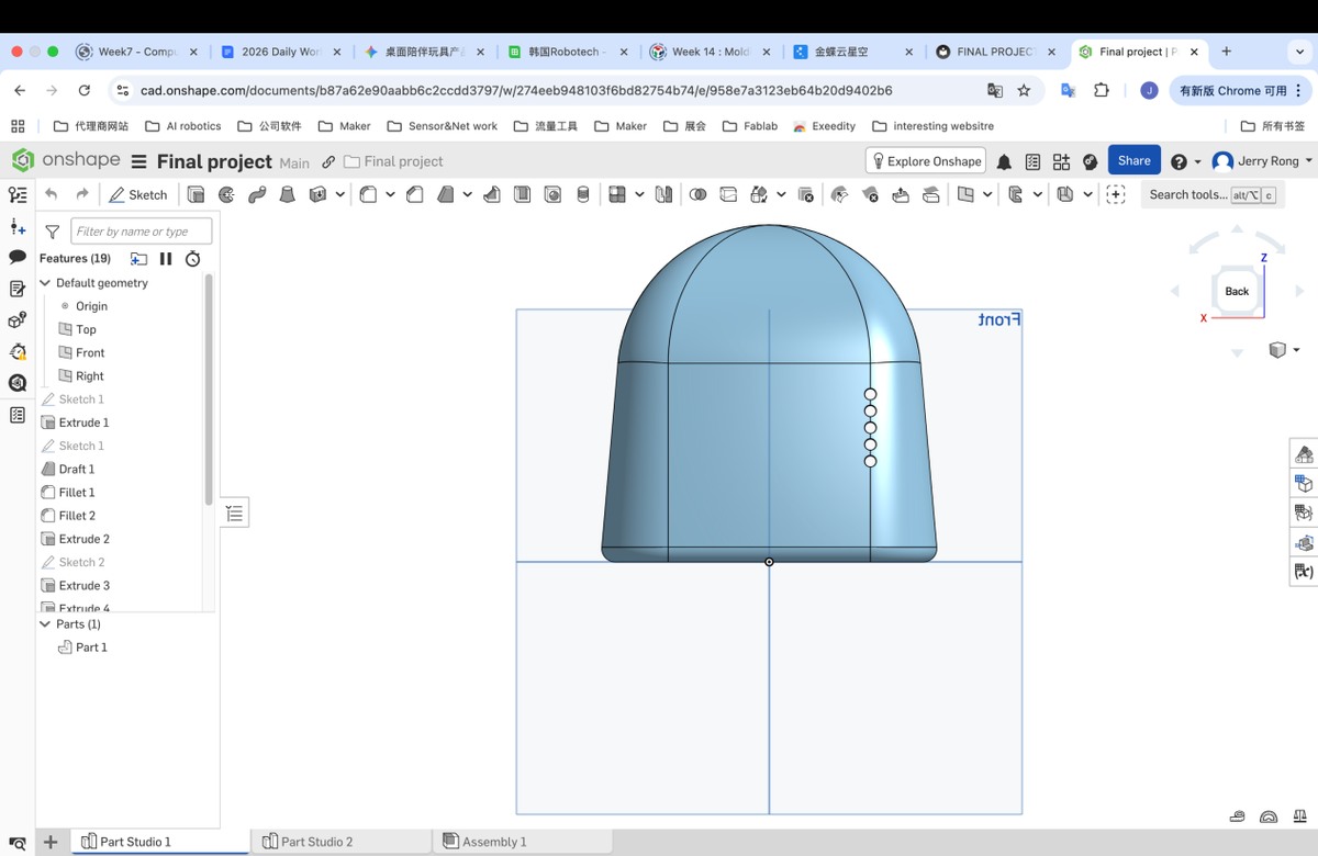
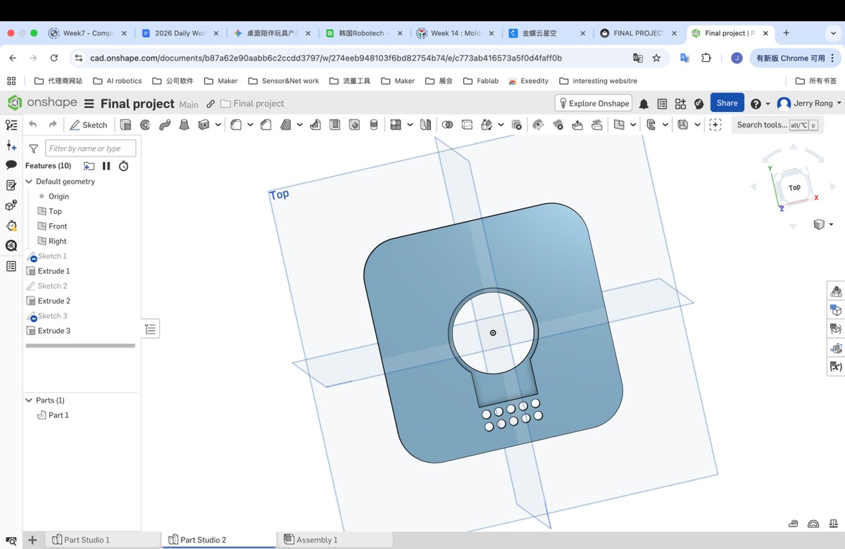
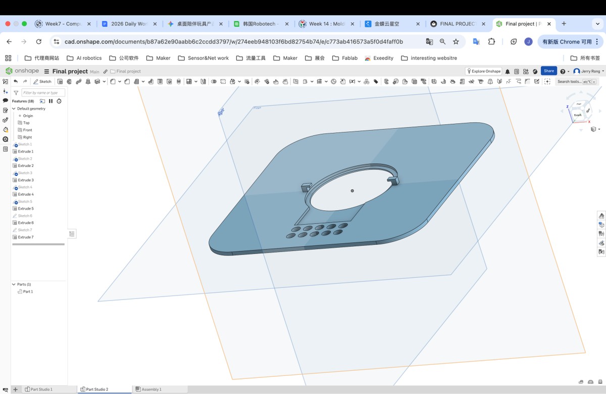
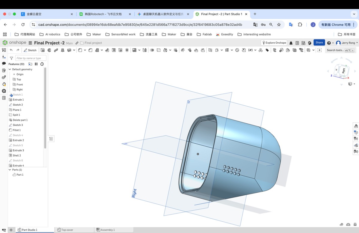
Make the 3D enclosure
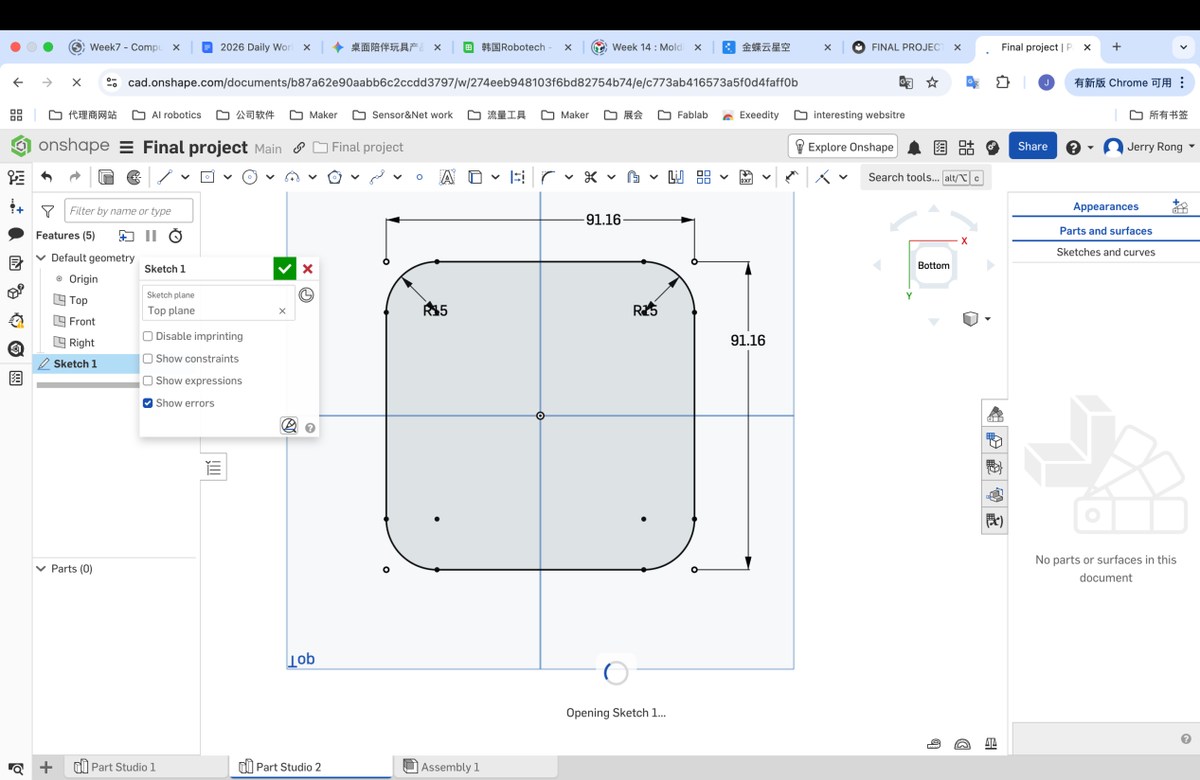
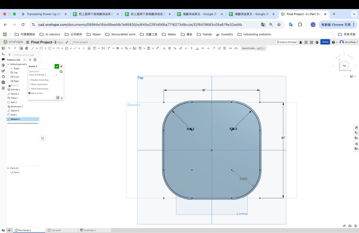
Step 1 draw a rectangle (100 x 100 mm) with Fillet (20mm)
Step 2 extrude with height 100 mm
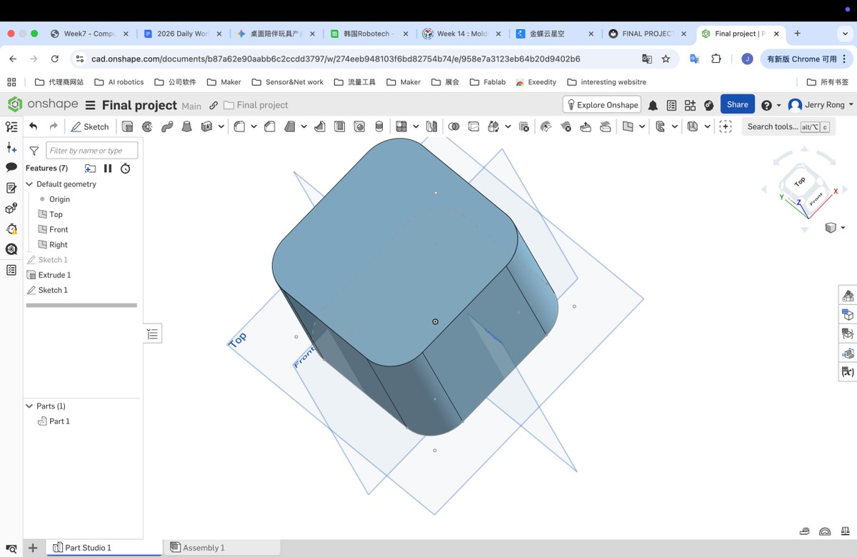
Step 3 use “Draft” to optimize the Cube
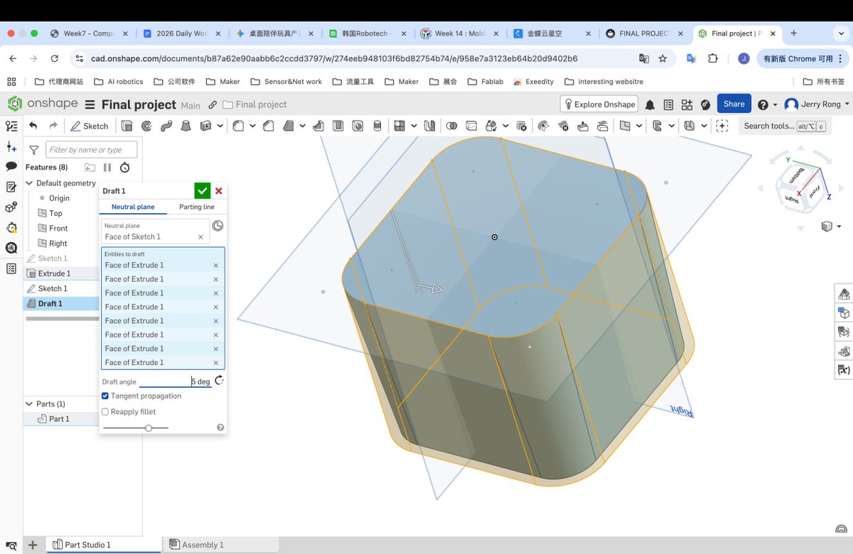
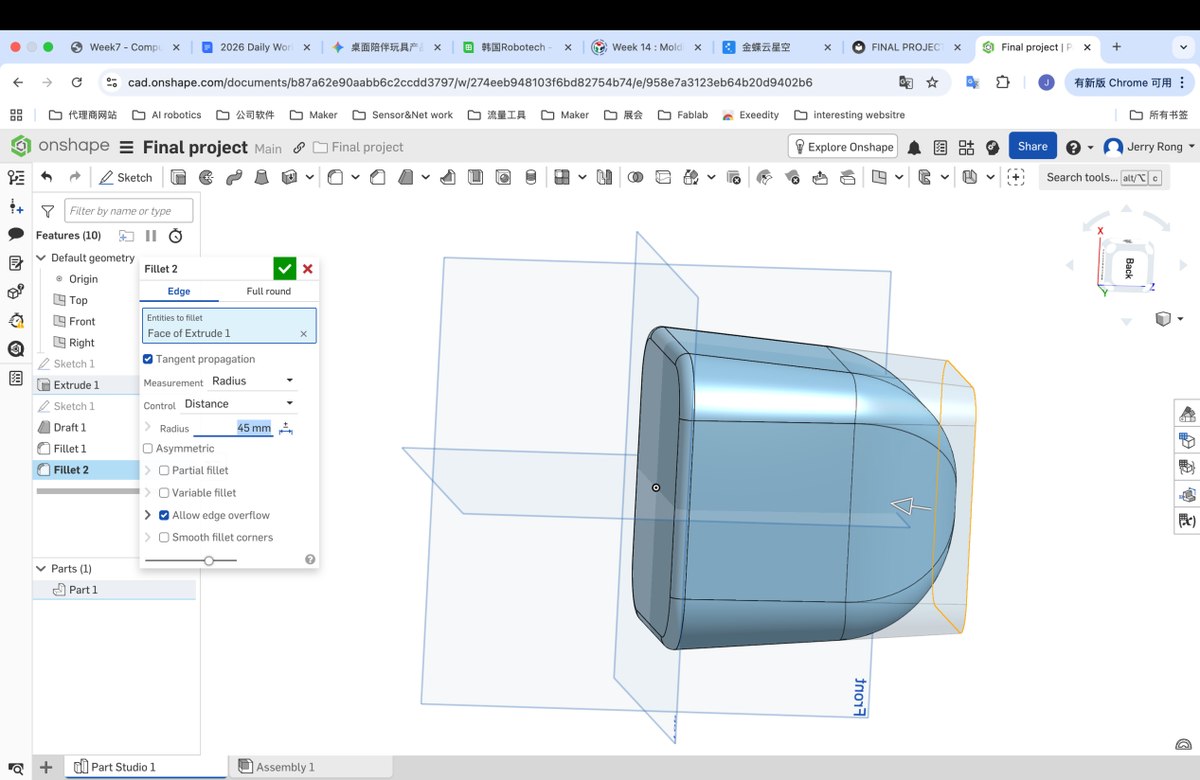
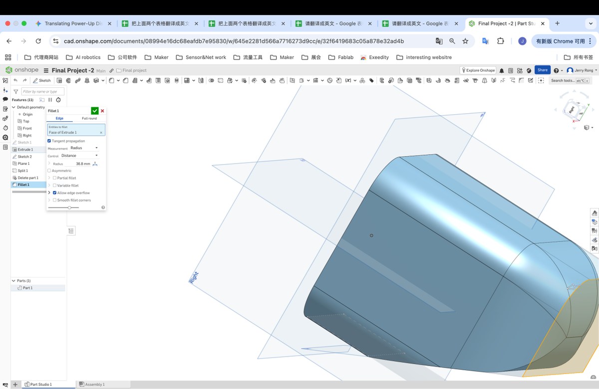
Step 4 Fillet to optimize the Top and bottom plane
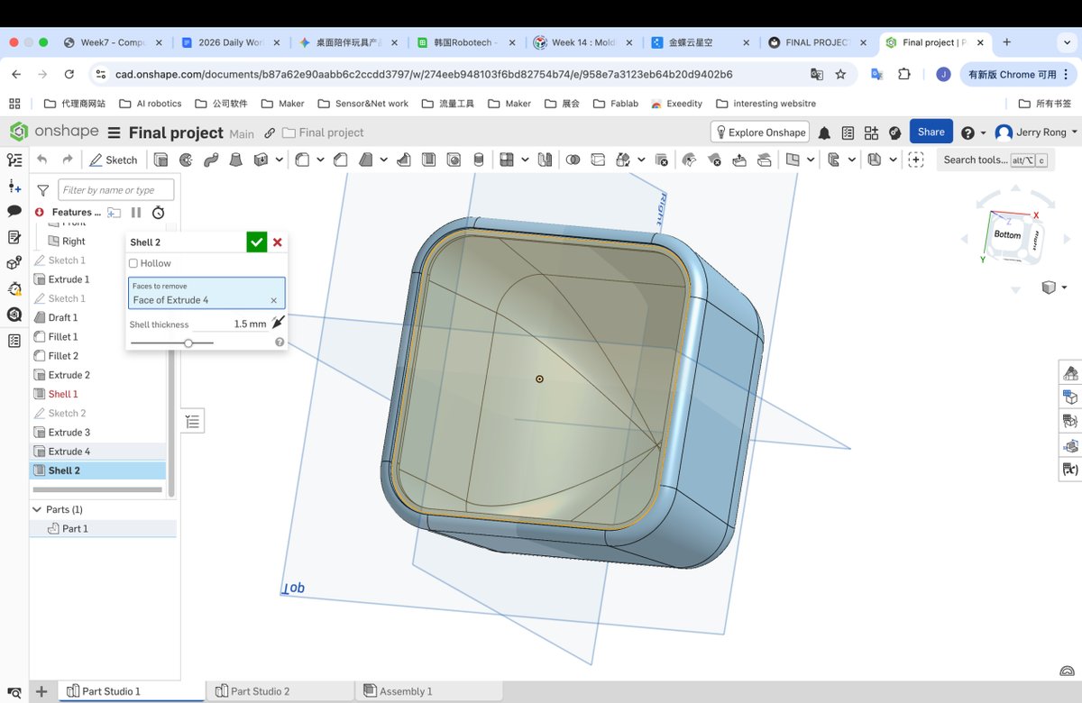
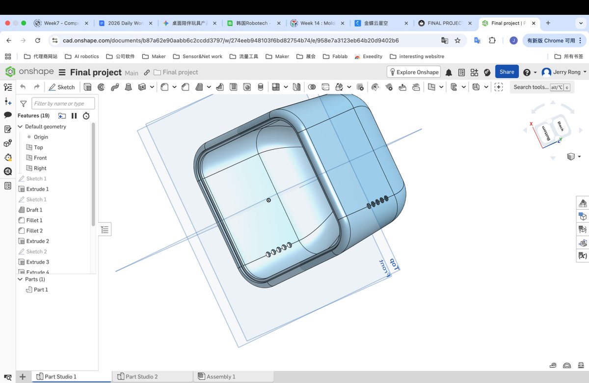
Step 5 make a basic plane to place the cover, depth is 1.5 mm, I will set the 1.5 mm as the thickness of the enclosure when “Shell” later
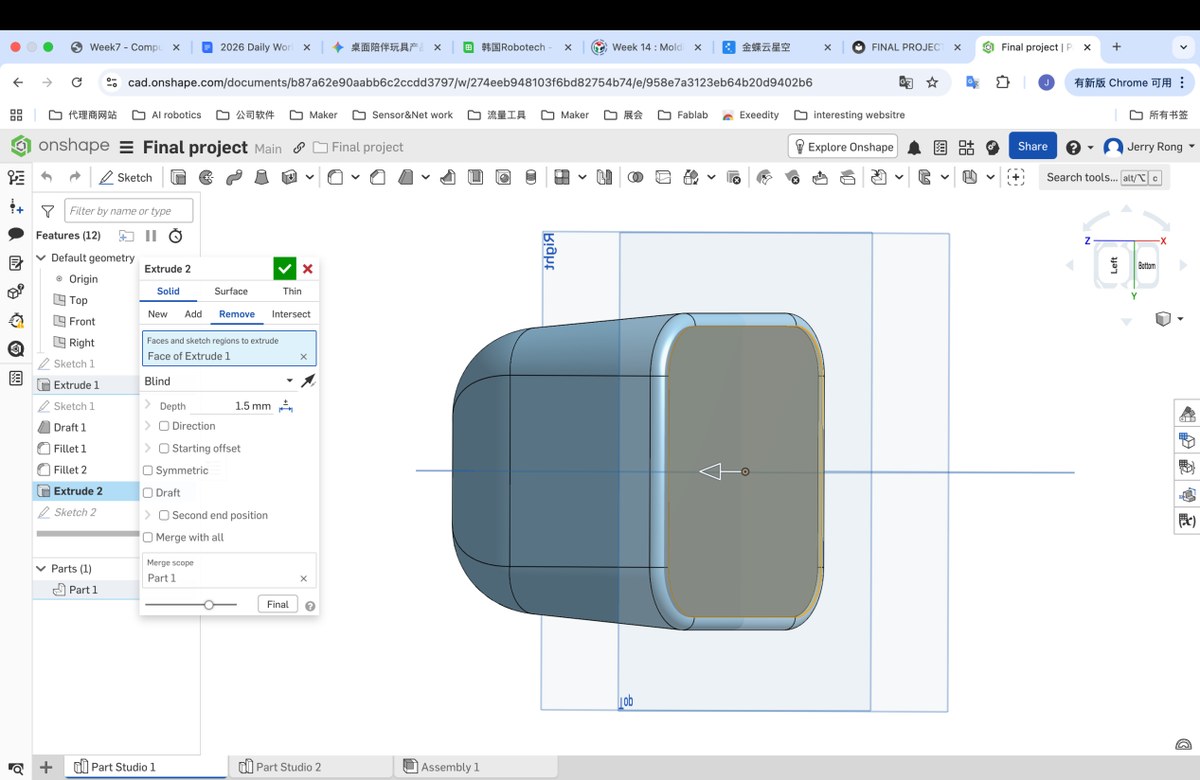
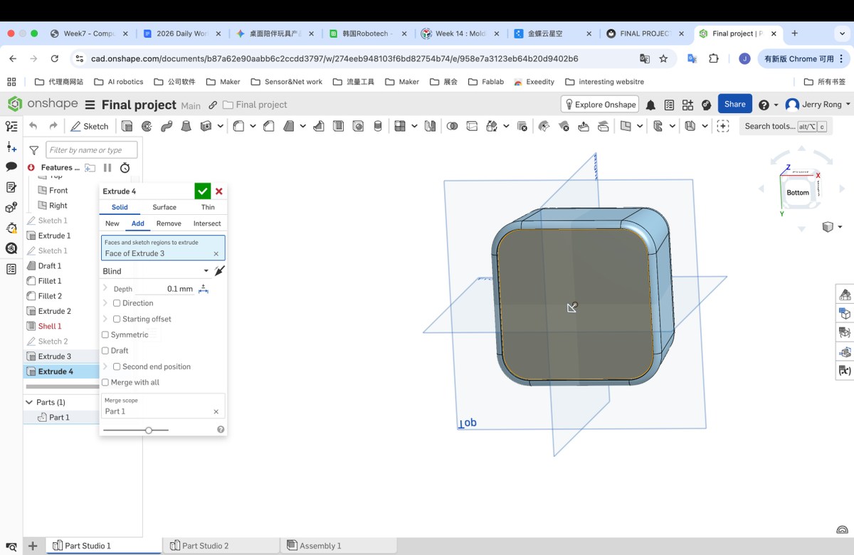
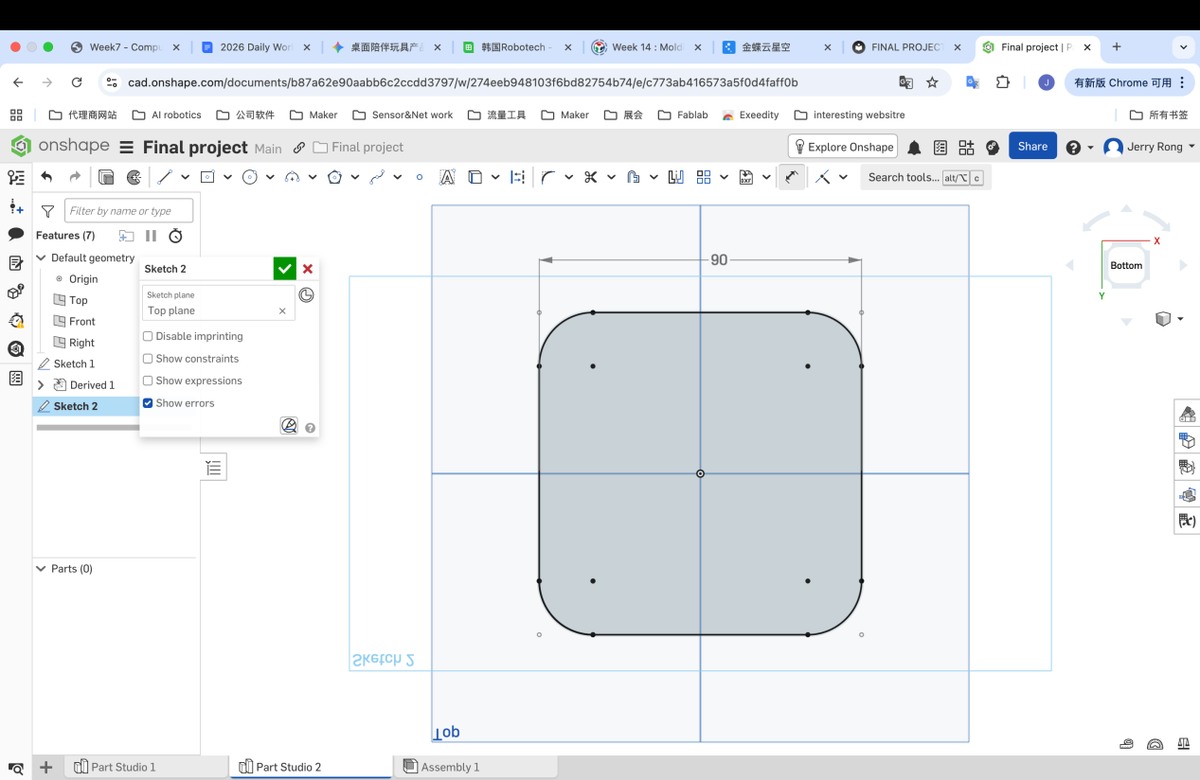
Create a smaller rectangle in the new plane for extrude

Step7 extrude the small rectangle with 0.1mm, to make a plane for Shell, as shell only proceed with plane.
Step6 Shell with the new plane, with thickness 1.5mm
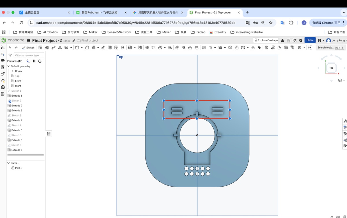
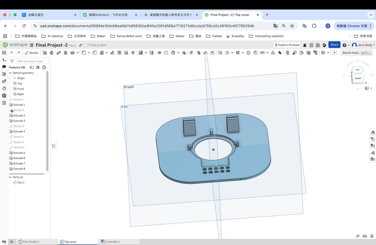
Step 7 make the plate for the LCD display.
7.1 Add Part studio 2, and use Derived to Copy the plane to make the plane directly.
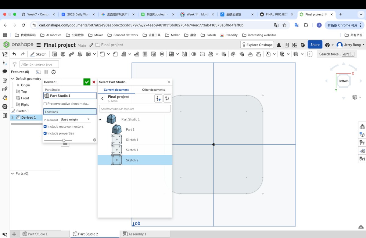
Use the Use/convert to make quoted rectangle to be revisable, as below, the line become black
The tolerance of 3D printing is 0.1 mm, the outline of the enclosure is 91.27mm
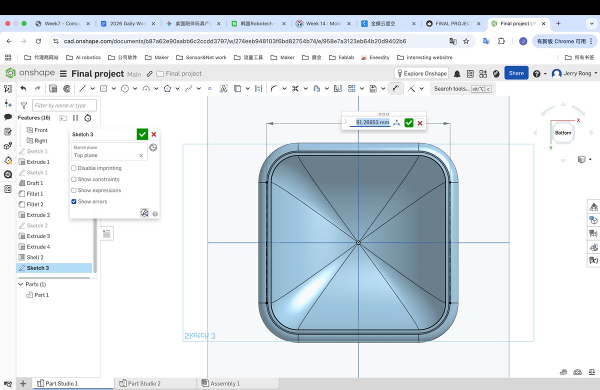
Then adjust the cover to be 91.16 mm
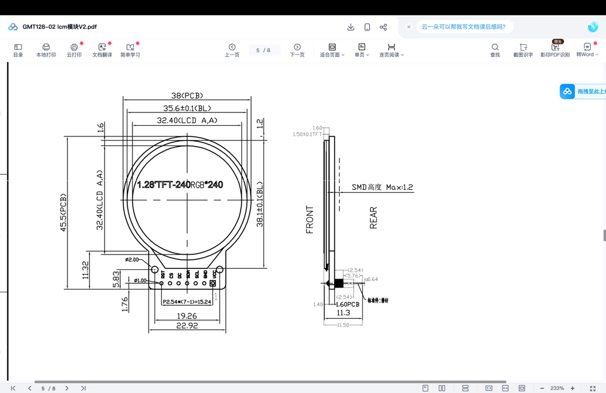
7.2 refer the size of the LCD to design the hole for the LCD
7.3 to place the display better, I need draw hole and Step layer, and then extrude
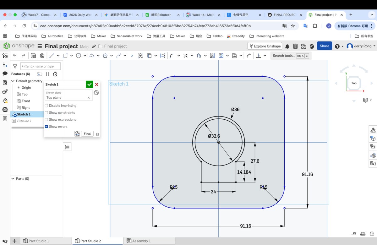
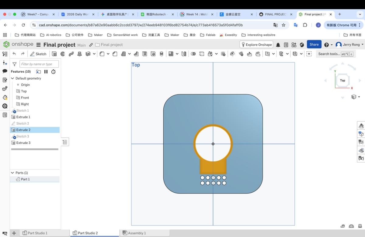
7.3 extrude and draw the hole on the cover plate and 2 sides, use Extrude to make the hole. Hole is for microphone.
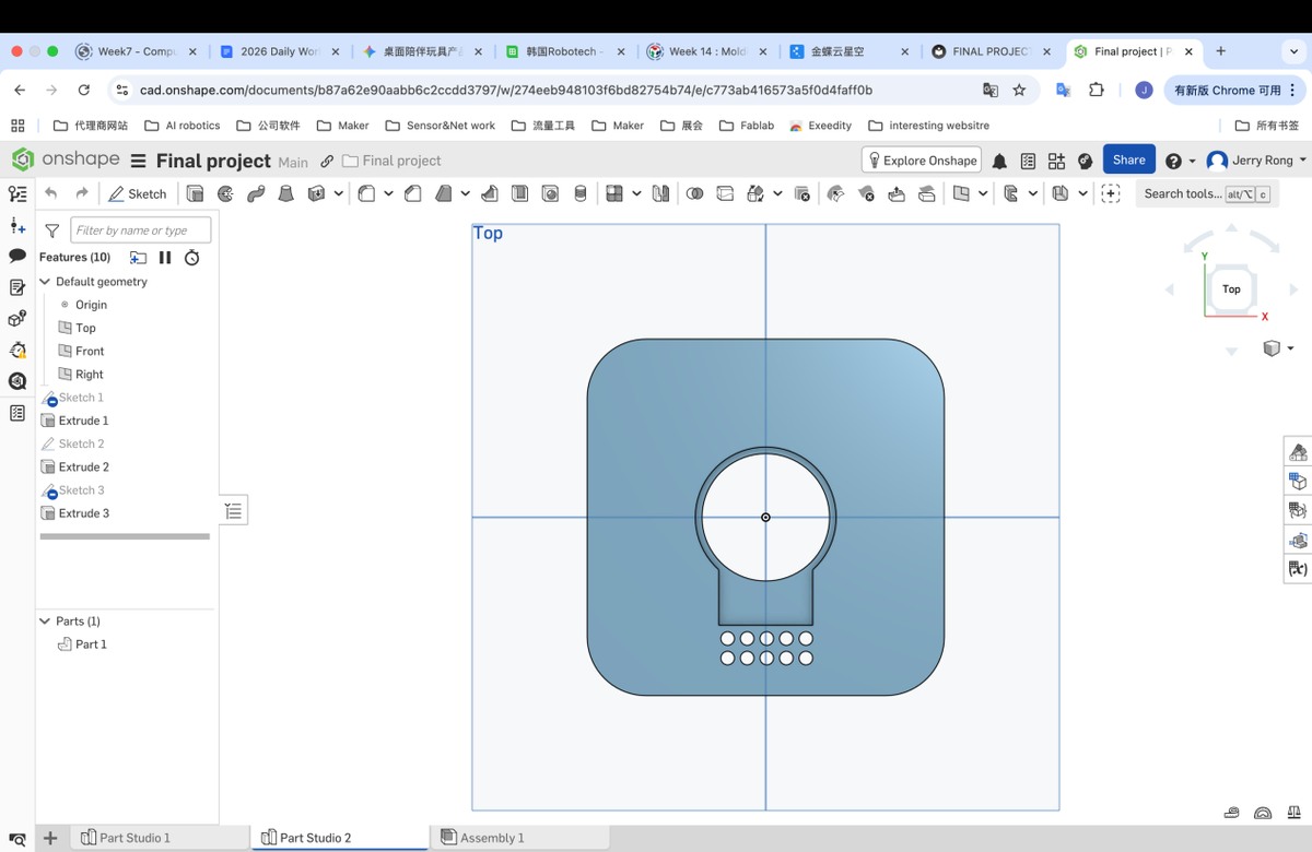
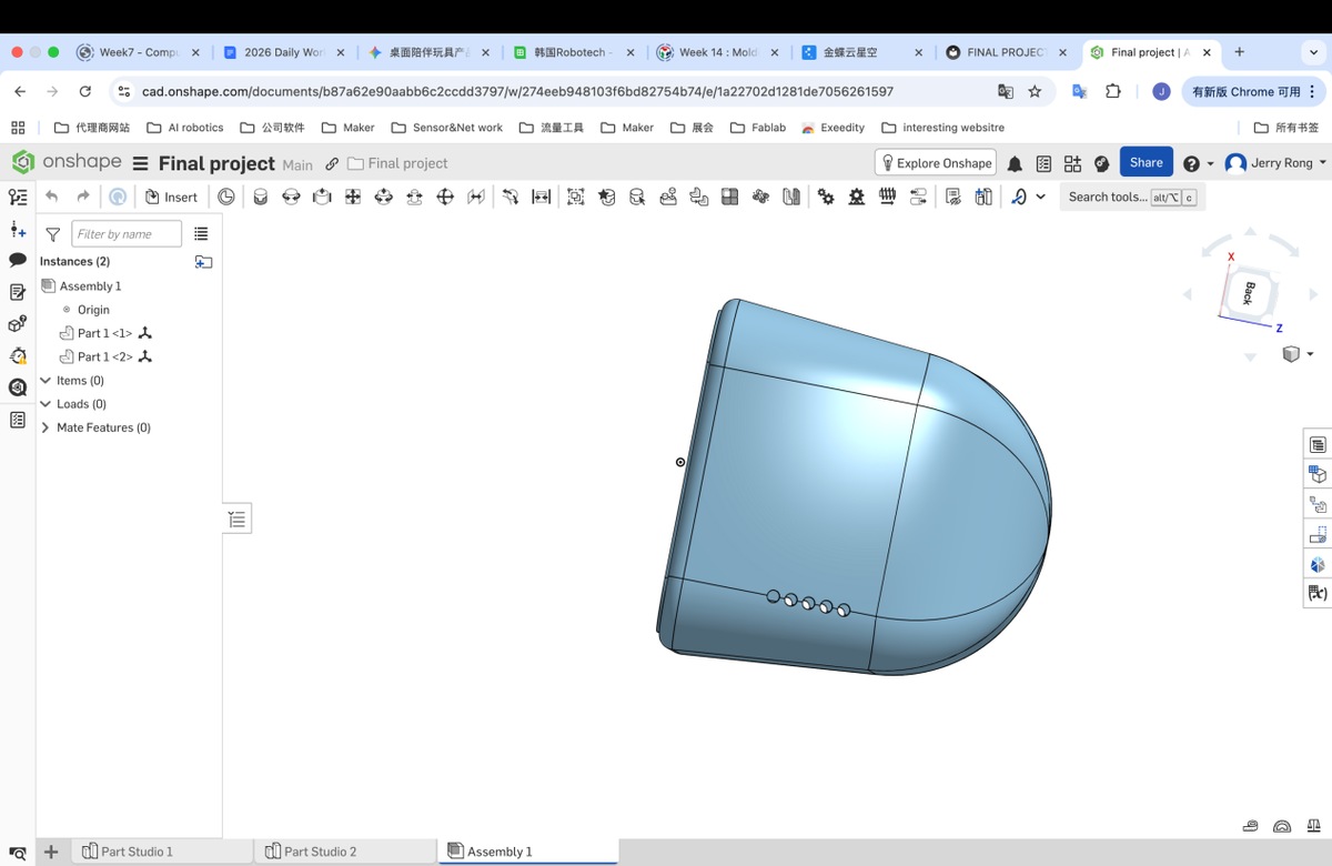
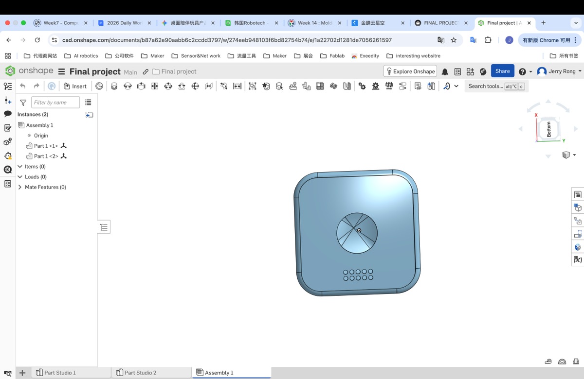
7.5 I finally got the 2 parts
7.6 assembly
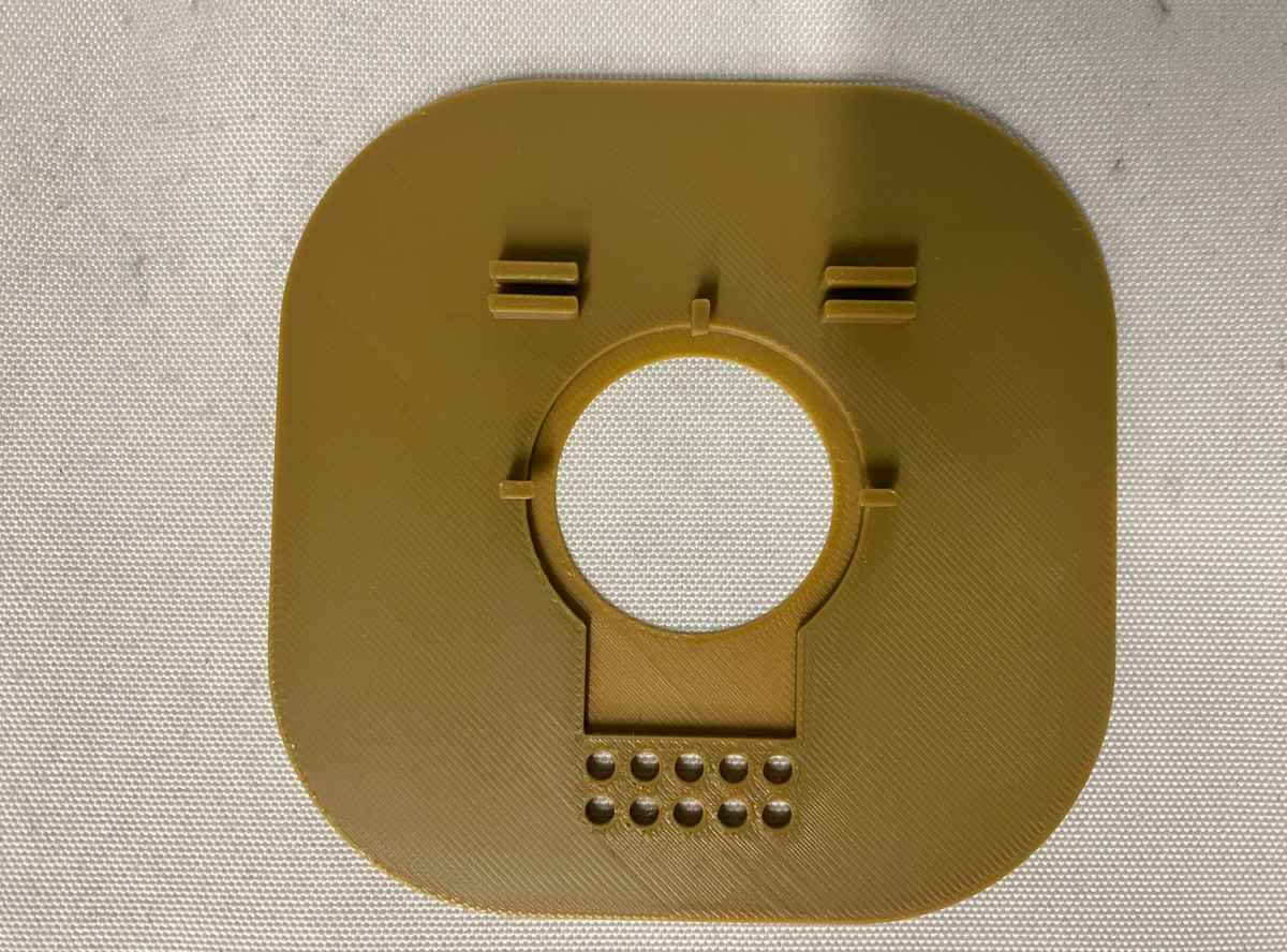
3D Printing
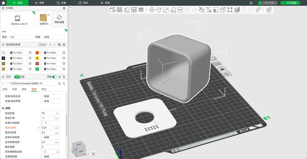
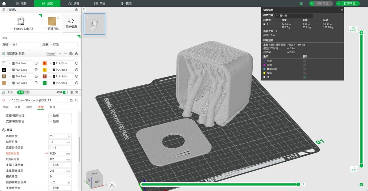
Printing (video as below)
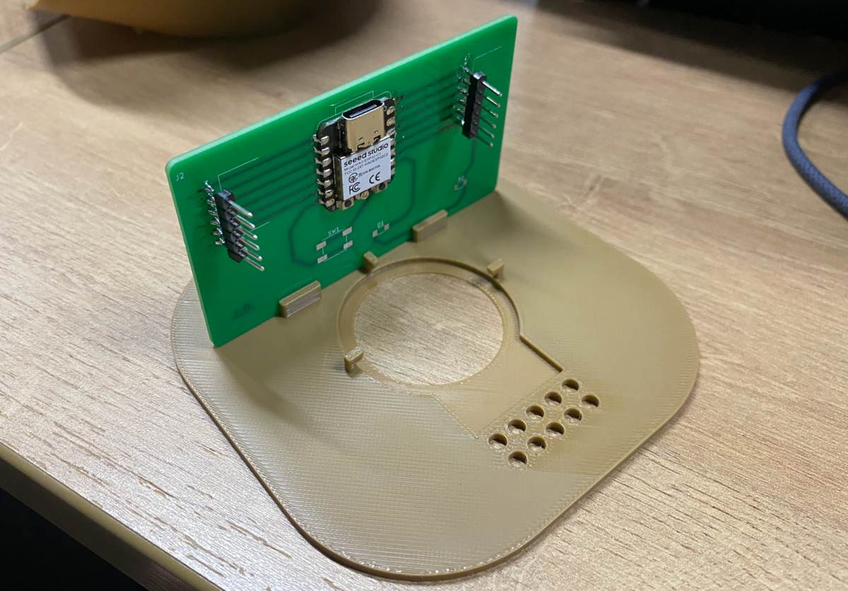
Update: for the Cover plate , I add 2 hook to fix the LCD PCB.
On 11th may, I Got 2 sets
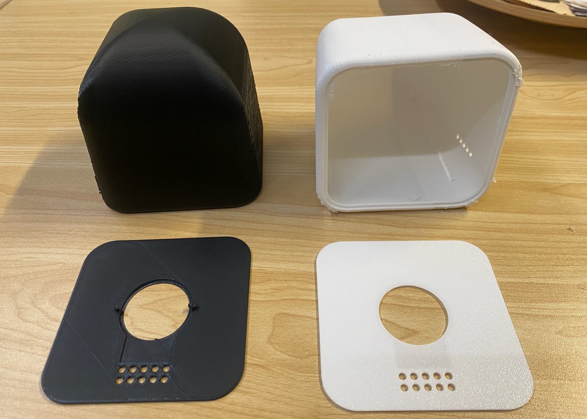
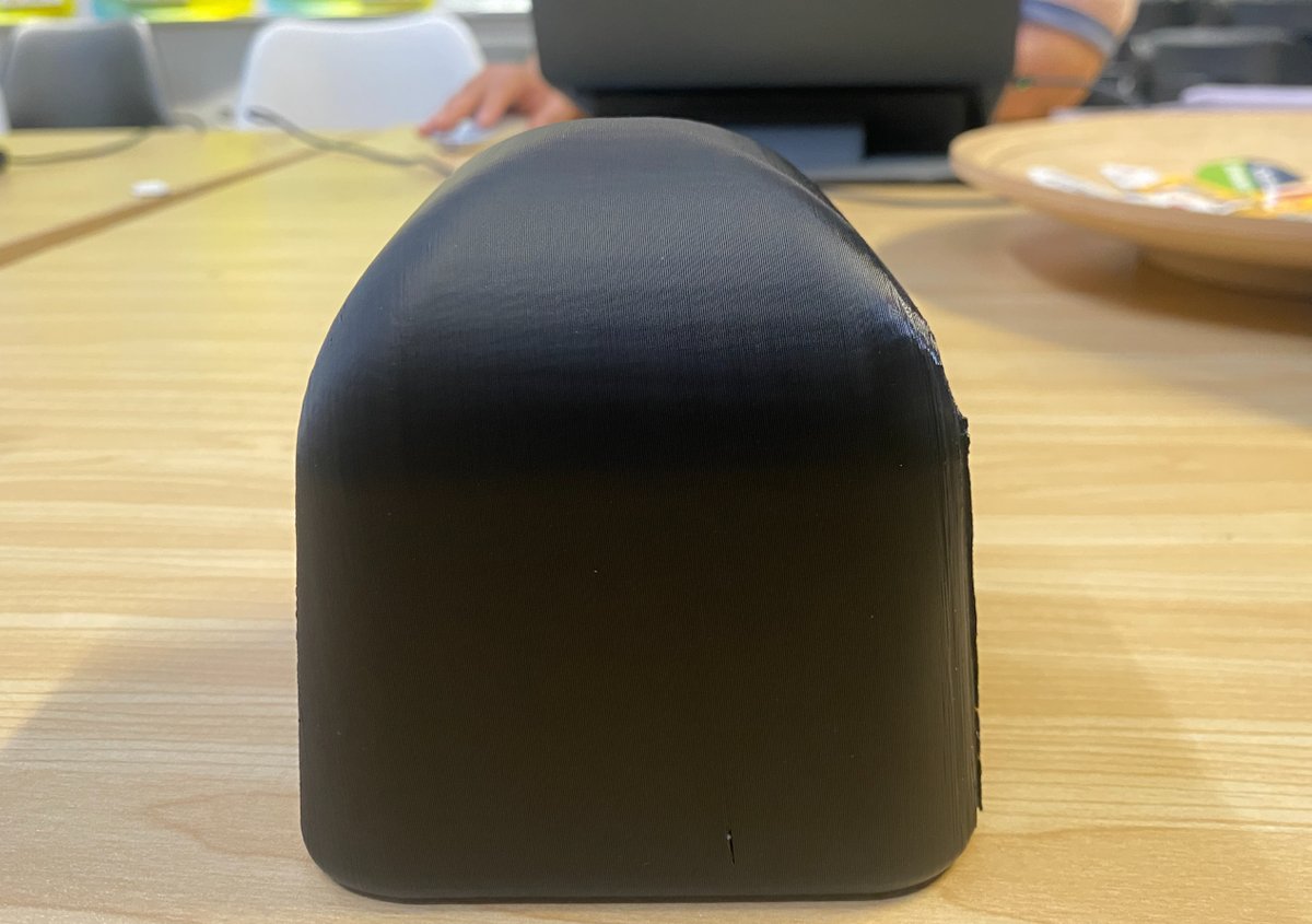
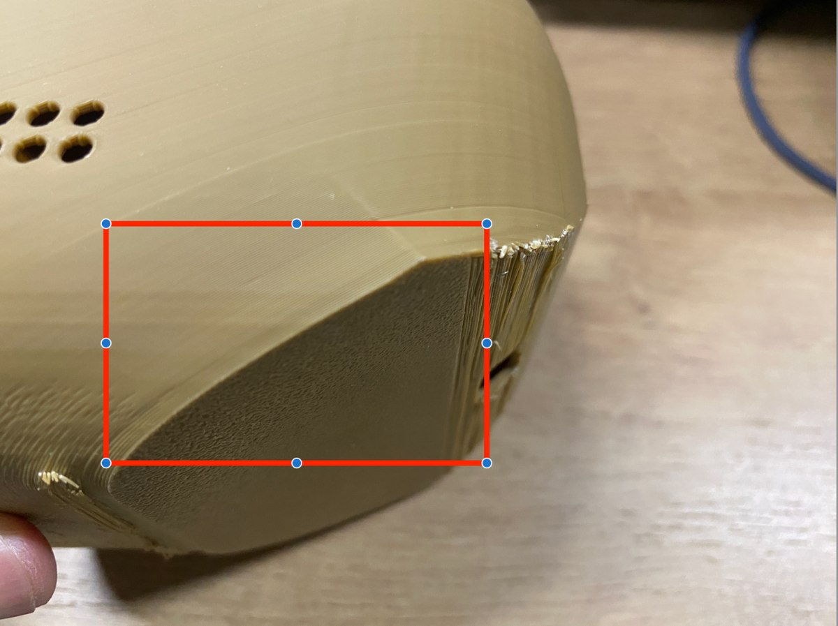
I see 2 issues need to be improved in my next version:
Error is not right, the cover not match the enclosure, the error should be 0.2mm or 0.3mm, I could try 0.3mm first for testing
“Noodles” on the surface, I need to adjust the slope to be more sharp,
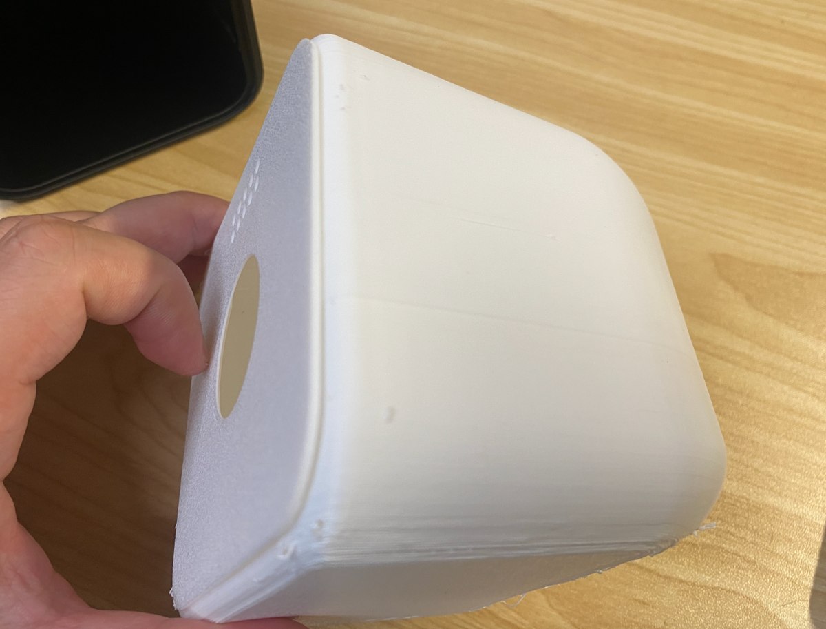
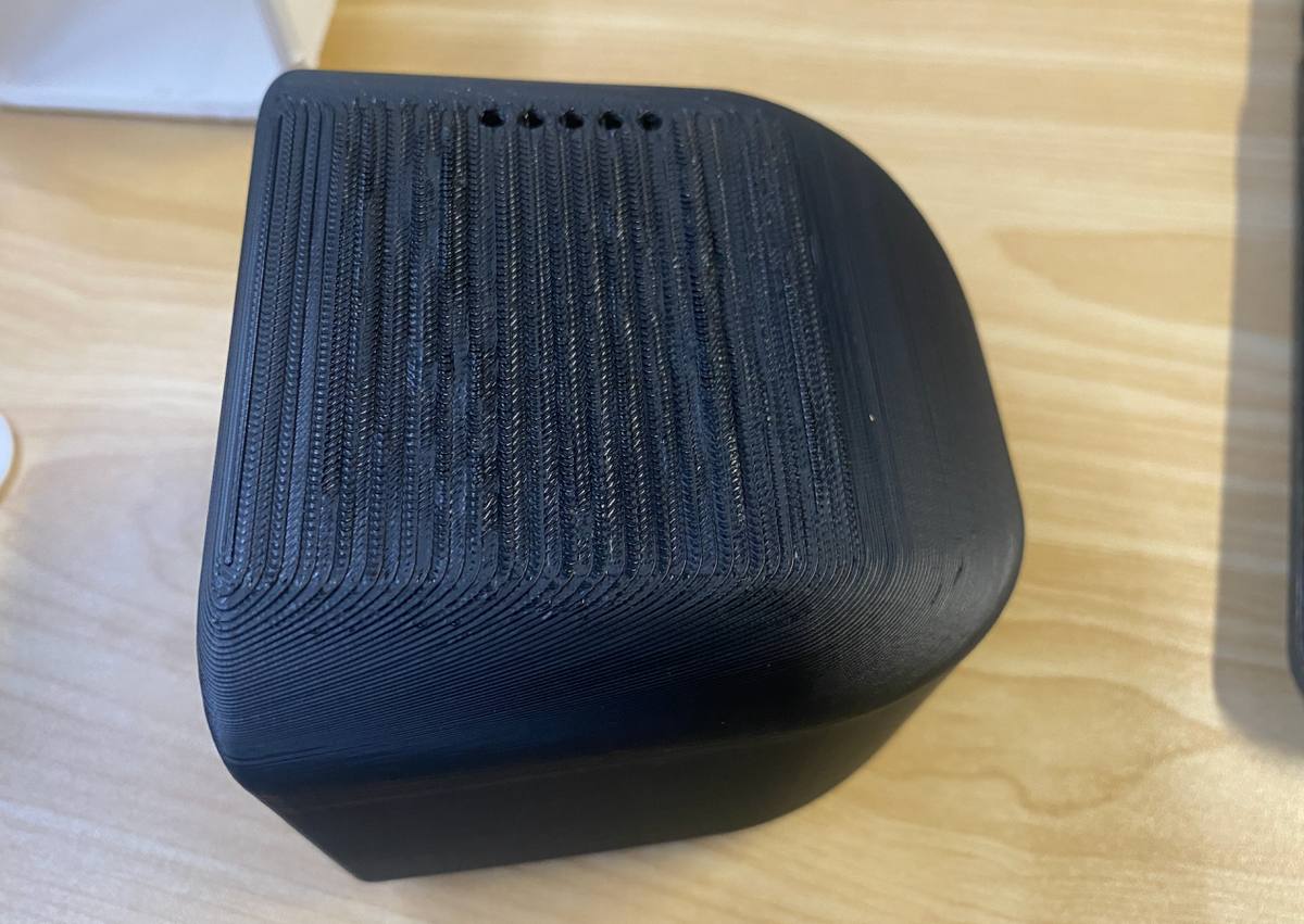
Or i can print the enclosure in another direction like picture below.
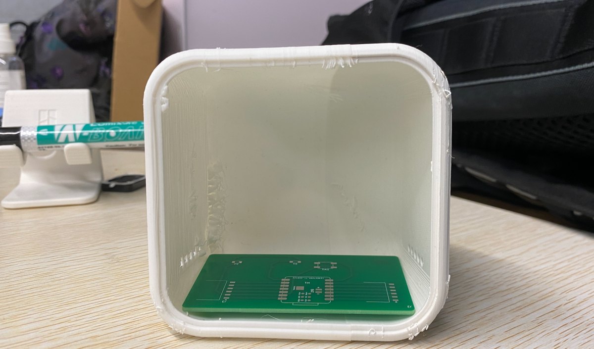
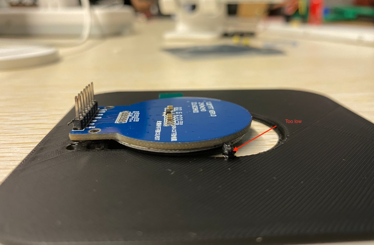
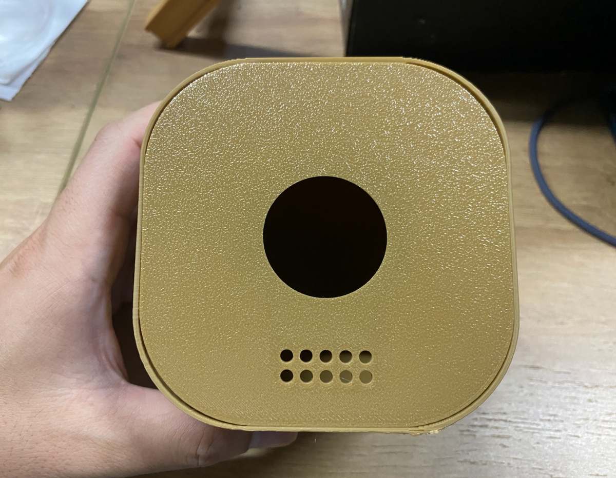
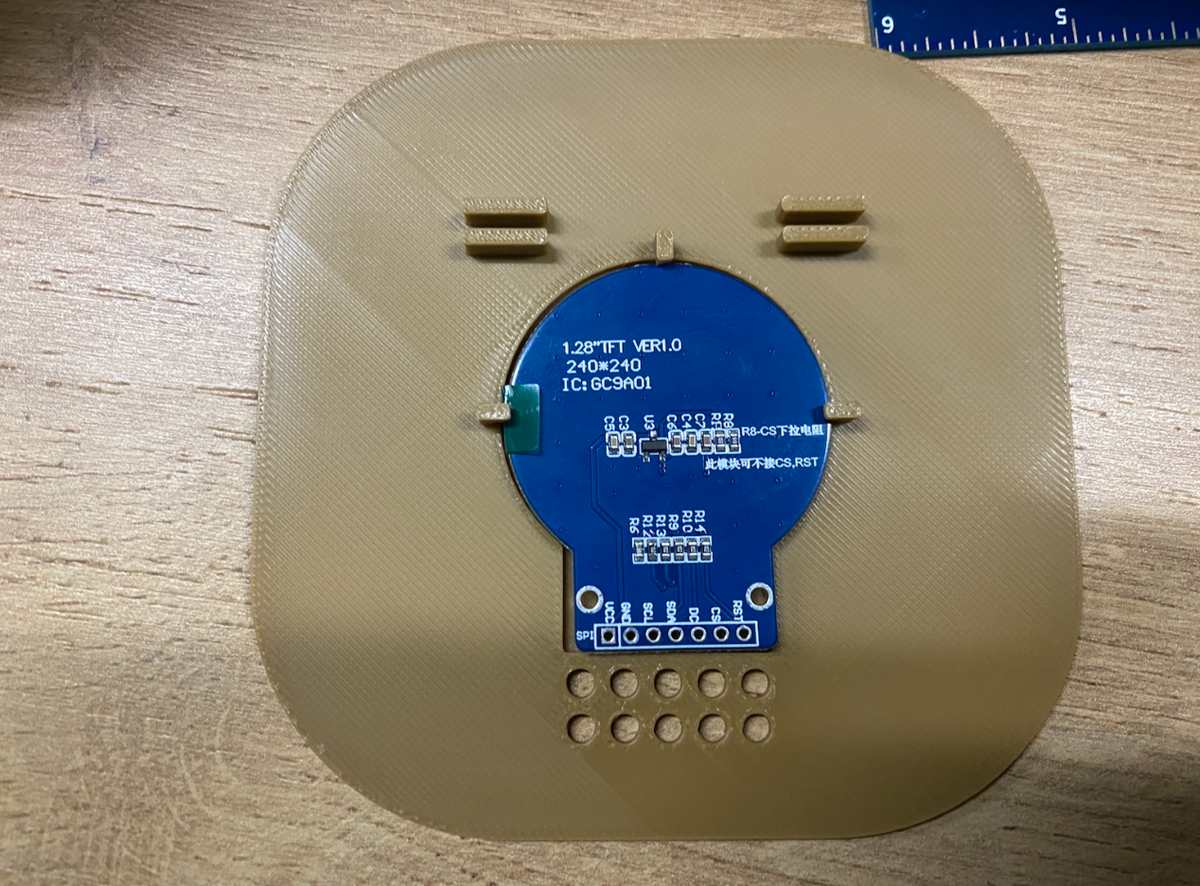
Update on 13th, May, I received the Mic and display as below, and then test Dimension testing with all parts
Display and microphone
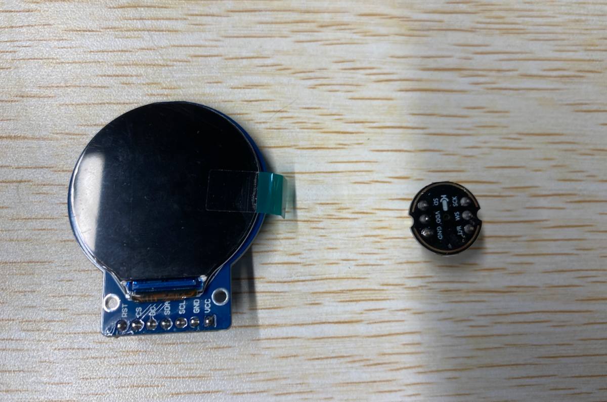
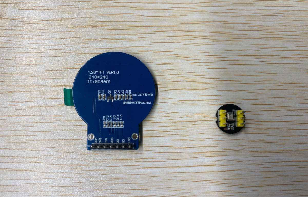
PCB can be placed inside of the enclosure.
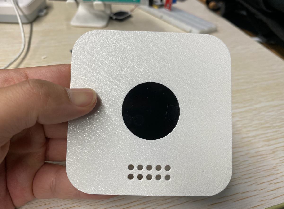
Try to match the display and display.
White cover plate + black display looks nice.
The diameter of the circle is some smaller, I need to adjust the diameter to be 35.8mm with 0.02mm margin
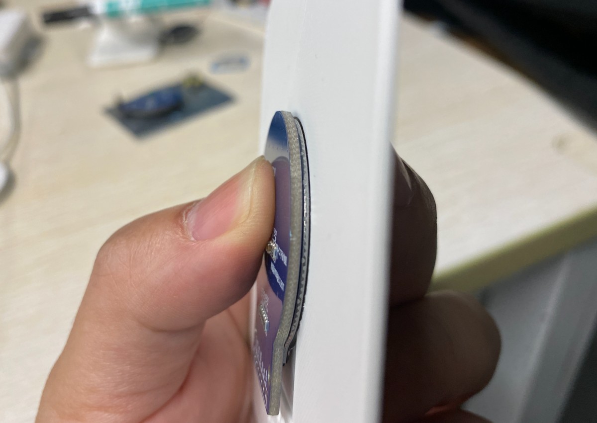
The limit stopper is too lower, the display cannot be inserted into the the part of circle. The height of stopper i will add 1mm first.
One more thing, I just realize I didn’t leave an hole for the Type C cable. I will revise all parts in the second version.
0516 make prototype of the electronics part first.
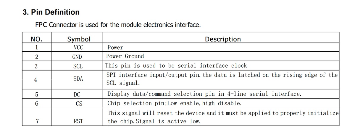
Learn basic information of the display and pin of the microphone and display.
Pin of Display
Pin of the mic

Translation to English:
SCK: Serial data clock for the I²S interface.
WS: Serial data word select for the I²S interface.
L/R: Left/Right channel selection.
When set to Low level (GND), the microphone outputs signals on the left channel of the I²S frame.
When set to High level (VCC), the microphone outputs signals on the right channel of the I²S frame.
SD: Serial data output for the I²S interface.
VCC: Power input, 1.8V to 3.3V
GND: Power ground.
Wiring
ESP32-C3 I/O
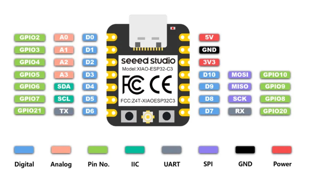
Microphone (INMP441) ➔ Seeed XIAO ESP32-C3 Wiring
Standard I2S digital audio bus connection:
| Microphone Pin (INMP441) | Seeed XIAO ESP32-C3 Physical Pin | Corresponding Pin in Code (GPIO) | Bus Function Description |
|---|---|---|---|
| VCC | 3.3V | 3.3V | Digital power supply for the microphone. |
| GND | GND | GND | Power ground. |
| L/R | GND | GND | Grounded (Low): Outputs Left Channel for single-channel (Mono) audio. |
| SCK | D2 | GPIO 4 | I2S Serial Bit Clock line (BCLK). |
| WS | D3 | GPIO 5 | I2S Word Select / Frame Clock line (LRCK). |
| SD | D1 | GPIO 3 | I2S Serial Data Out line (audio data input to the MCU). |
2.Round Screen (GMT128-02 / GC9A01) ➔ Seeed XIAO ESP32-C3 Wiring
4-line SPI serial bus connection:
| Screen Pin (GMT128-02) | Seeed XIAO ESP32-C3 Physical Pin | Corresponding Pin in Code (GPIO) | Adjustment & Advantage Description |
|---|---|---|---|
| 1. VCC | 5V | 5V | Connects to the stable 5V rail to ensure enough power for the backlight. |
| 2. GND | GND | GND | Power ground (must share a common ground with the microphone). |
| 3. SCL | D8 | GPIO 8 | Hardware Fixed: SPI Serial Clock line (SCK). |
| 4. SDA | D10 | GPIO 10 | Hardware Fixed: SPI Serial Data Out line (MOSI). |
| 5. DC | D4 | GPIO 6 | Data/Command selection pin. |
| 6. CS | D0 | GPIO 2 | Strapping Pin Warning: Please check the crucial boot note below. |
| 7. RST | D5 | GPIO 7 | Hardware reset pin (active low). |
With a breadboard and cable
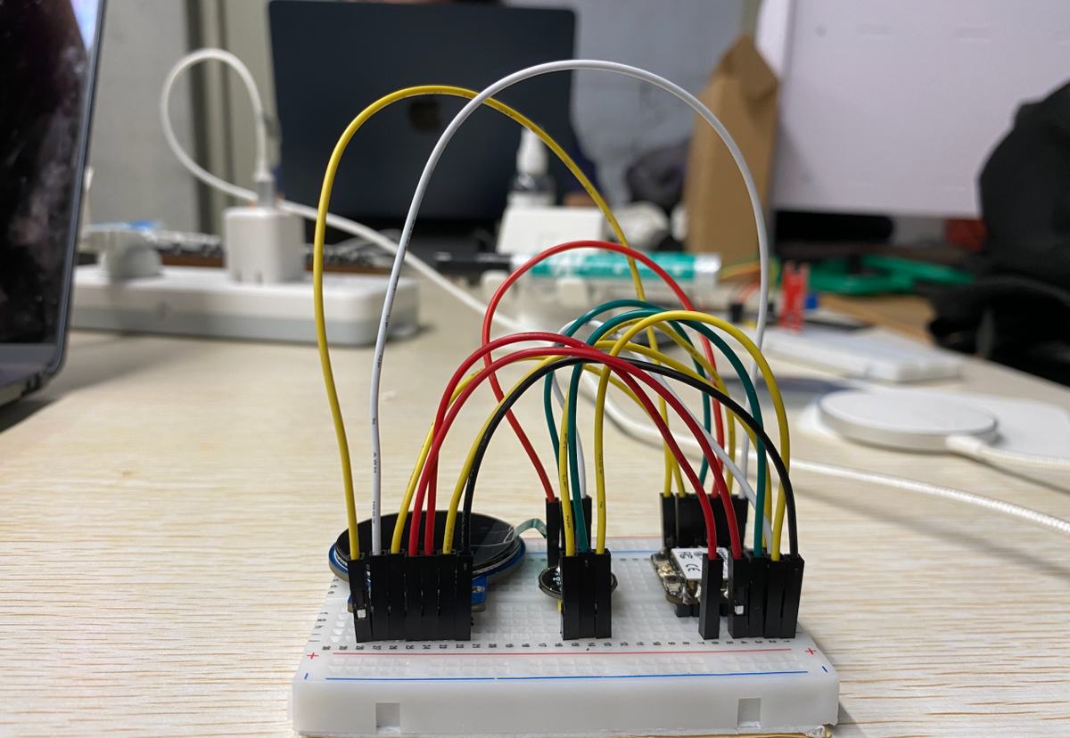
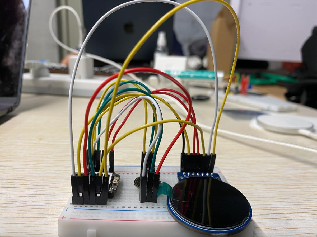
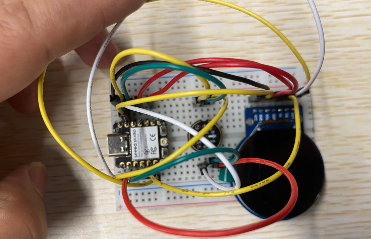
Debug the prototype
Step 1 connect the prototype with Laptop
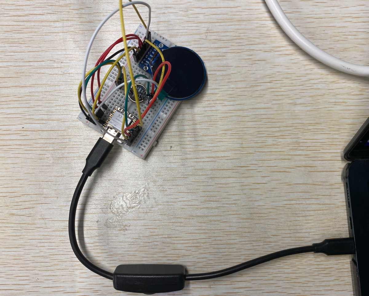
Step 2 use cursor to debug
ask Cursor to check the connection
Tell Cursor the demand: Xiao ESP32-C3 + display(GC9A01)+ mic (INMP441)
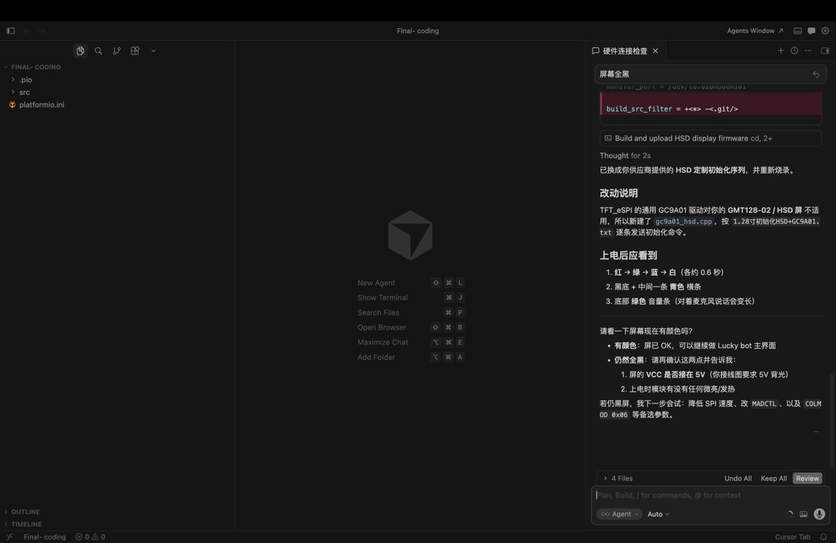
C。Cursor check with on the Pin connection, I send the setting above by picture.
Debug on the connection, setting as below from Cursor.
Upon powering up, you should observe the following:
Red → Green → Blue → White (approx. 0.6 seconds each)
Black background with a cyan horizontal bar in the center
A green volume bar at the bottom (elongates when speaking into the microphone)
Key source code — hardware debug (May 16)
Early prototype test firmware for Xiao ESP32-C3 + GC9A01 round LCD + INMP441 mic.
The standalone debug sketch was later merged into the full Lucky Bot firmware; the pin map and drivers below are from the current project and match this breadboard test.
1. Pin map (src/gc9a01_hsd.h, src/mic_i2s.cpp):
// GC9A01 round LCD (SPI)
constexpr int PIN_LCD_CS   = 2;   // D0
constexpr int PIN_LCD_DC   = 6;   // D4
constexpr int PIN_LCD_RST  = 7;   // D5
constexpr int PIN_LCD_SCK  = 8;   // D8
constexpr int PIN_LCD_MOSI = 10;  // D10

// INMP441 microphone (I2S)
constexpr gpio_num_t I2S_PIN_BCLK = GPIO_NUM_4;  // D2
constexpr gpio_num_t I2S_PIN_WS   = GPIO_NUM_5;  // D3
constexpr gpio_num_t I2S_PIN_DIN  = GPIO_NUM_3;  // D1
2. LCD init — vendor HSD sequence (src/gc9a01_hsd.cpp):
bool GC9A01_HSD::begin() {
  pinMode(PIN_LCD_CS, OUTPUT);
  pinMode(PIN_LCD_DC, OUTPUT);
  pinMode(PIN_LCD_RST, OUTPUT);

  digitalWrite(PIN_LCD_RST, LOW);
  delay(20);
  digitalWrite(PIN_LCD_RST, HIGH);
  delay(120);

  spi_.begin(PIN_LCD_SCK, -1, PIN_LCD_MOSI, -1);
  spi_.beginTransaction(SPISettings(27000000, MSBFIRST, SPI_MODE0));

  runHsdInit();   // GC9A01 vendor init from 1.28" HSD datasheet
  Serial.println("[LCD] HSD GC9A01 init done");
  return true;
}
3. Microphone init (src/mic_i2s.cpp):
bool micBegin() {
  i2s_config_t cfg = {};
  cfg.mode = (i2s_mode_t)(I2S_MODE_MASTER | I2S_MODE_RX);
  cfg.sample_rate = 16000;
  cfg.bits_per_sample = I2S_BITS_PER_SAMPLE_32BIT;
  cfg.channel_format = I2S_CHANNEL_FMT_ONLY_LEFT;

  i2s_pin_config_t pins = {};
  pins.bck_io_num = I2S_PIN_BCLK;
  pins.ws_io_num = I2S_PIN_WS;
  pins.data_in_num = I2S_PIN_DIN;

  i2s_driver_install(I2S_NUM_0, &cfg, 0, nullptr);
  i2s_set_pin(I2S_NUM_0, &pins);
  return true;
}
4. Boot test — colour flash + live mic level bar (early debug main.cpp logic):
#include "gc9a01_hsd.h"
#include "mic_i2s.h"

GC9A01_HSD lcd;

void bootColorTest() {
  const uint16_t colors[] = {COLOR_RED, COLOR_GREEN, COLOR_BLUE, COLOR_WHITE};
  for (uint16_t c : colors) {
    lcd.fillScreen(c);
    delay(600);   // ~0.6 s each — confirms SPI + display wiring
  }
}

void drawMicLevel(int32_t rms) {
  lcd.fillScreen(COLOR_BLACK);
  lcd.fillRect(0, 110, 240, 20, COLOR_CYAN);              // centre bar
  const int w = constrain(map(rms, 0, 2500, 0, 240), 0, 240);
  lcd.fillRect(0, 220, w, 16, COLOR_GREEN);             // volume bar
}

void setup() {
  Serial.begin(115200);
  lcd.begin();
  bootColorTest();
  micBegin();
}

void loop() {
  int16_t samples[320];
  const size_t n = micReadSamples(samples, 320, 50);
  int64_t sum = 0;
  for (size_t i = 0; i < n; i++) sum += (int64_t)samples[i] * samples[i];
  const int32_t rms = n ? (int32_t)sqrt((double)sum / n) : 0;
  drawMicLevel(rms);
  delay(50);
}
Expected result on screen: Red → Green → Blue → White, then black screen with cyan centre bar and a green bottom bar that grows when speaking into the mic.
Key source code — microphone recording (INMP441 @ 16 kHz)
Firmware on Seeed Xiao ESP32-C3 + INMP441 reads audio over I2S, records PCM until silence (VAD), wraps a WAV file, and uploads to the Mac ASR server.
Project files: src/mic_i2s.cpp, wav_util.cpp, main.cpp, asr_client.cpp
1. Audio config (include/lucky_config.h):
constexpr uint32_t kMicSampleRate = 16000;      // 16 kHz mono
constexpr uint32_t kMaxRecordSeconds = 4;       // max buffer after WiFi up
constexpr uint32_t kSilenceStopMs = 800;        // pause this long → stop recording
constexpr uint32_t kMinSpeechMs = 500;          // ignore clicks shorter than this
constexpr int32_t kSpeechRmsThreshold = 420;    // RMS threshold — lower = more sensitive
constexpr uint32_t kMaxWaitSpeechMs = 12000;    // wait for user to start speaking
2. Record until silence (VAD) — main recording path (micRecordUntilSilence):
size_t micRecordUntilSilence(uint8_t* pcmOut, size_t pcmMax, uint32_t maxCaptureMs,
                             bool waitForSpeech, uint32_t maxWaitMs) {
  // Wait for speech (RMS >= threshold), capture PCM, stop after kSilenceStopMs of silence.
  constexpr uint32_t kFrameSamples = 320;  // 20 ms @ 16 kHz
  // ... frame RMS loop, write PCM bytes ...
  if (heardSpeech && speechMs >= kMinSpeechMs && silenceMs >= kSilenceStopMs)
    return outBytes;
  return 0;
}
3. WAV header + record + upload (src/main.cpp → recordAndUpload()):
writeWavHeader(wavBuffer, kMicSampleRate, 16, 1, (uint32_t)got);
const size_t totalLen = kWavHeaderSize + got;
micEnd();  // mute mic during upload

ChatResult chat = uploadVoiceChat(wavBuffer, totalLen, serverHost, serverPort);
if (chat.ok) {
  Serial.println("[YOU]  " + chat.userText);
  Serial.println("[Lucky] " + chat.reply);
}
Expected behaviour: speak into the mic → serial log shows [REC] speech start → after ~0.8 s silence, WAV uploaded → Mac returns transcribed text + bot reply.
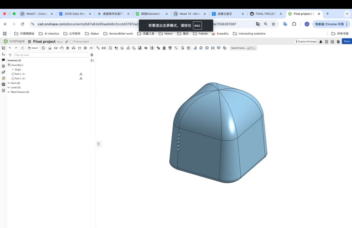
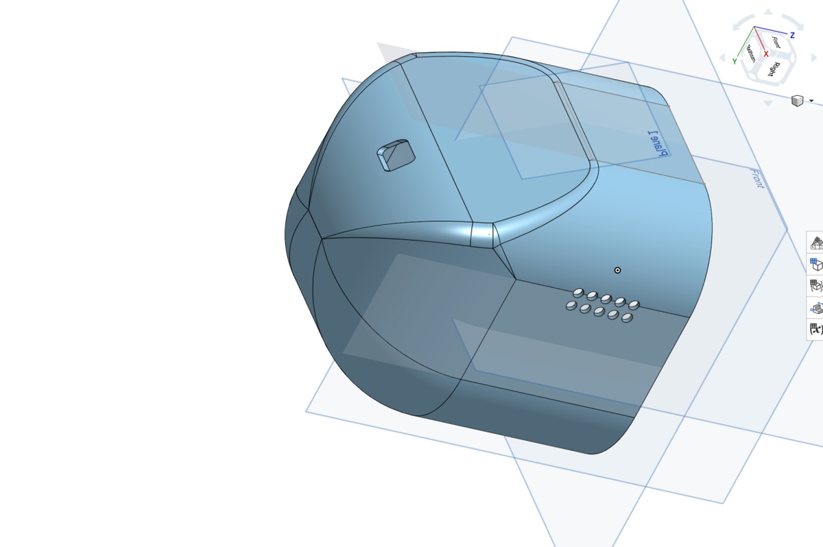
0517 Update enclosure,
I wanna revise the design more close to the effect picture.
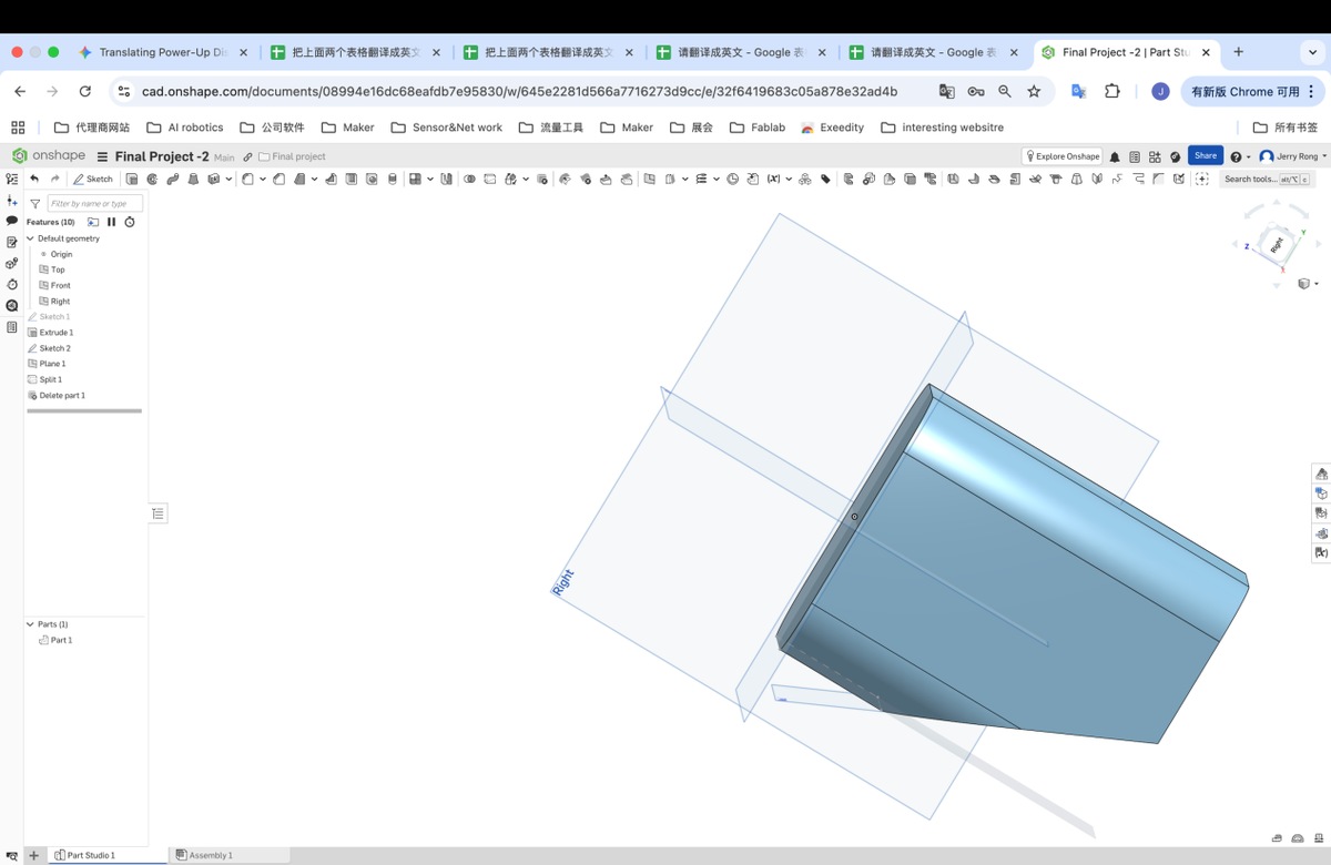
I create a Cube with chamfer, steps smilar with before, and use Plane - Line angle with setting below,
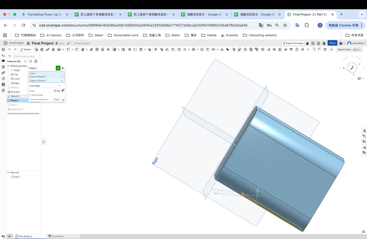
Then remove the part 2, much more closer
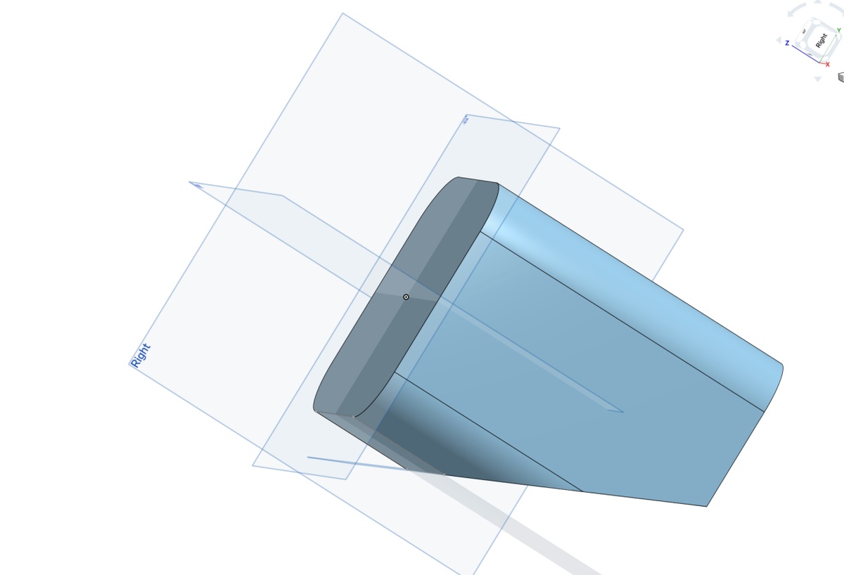
Fillet with setting below , looks good
Revise the dimension, finalize as below
Extrude, depth 2.5 mm
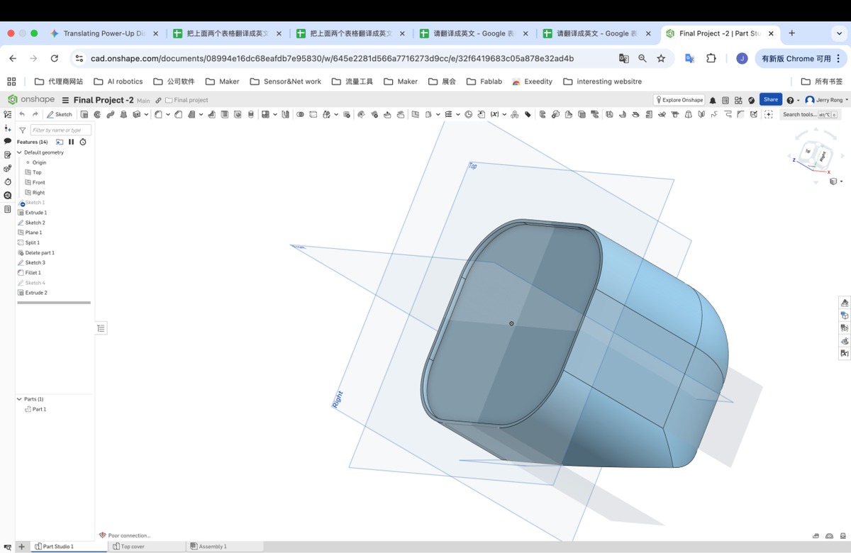
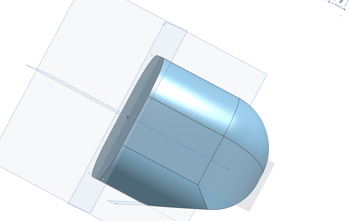
The update 3D is as below
Add the blocks to inserts the PCBA
0525 update
The updated enclosure with 3D printing
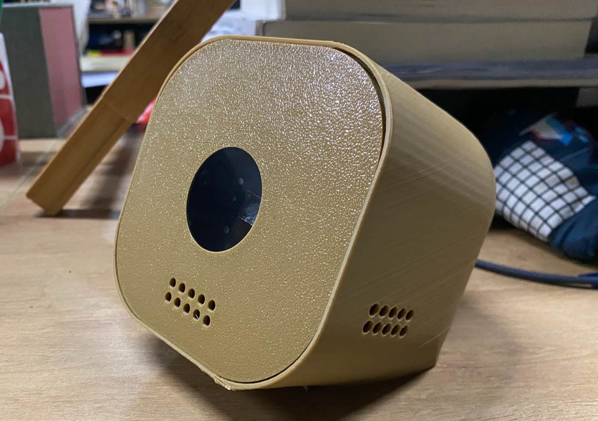
Some parts to be improved :
Gap between top cover and the enclosure, I need to adjust the fillet of the cover plate, radius = 28.5 -0.2(error) = 28.3 mm
The heights of blocks need to be increased, +10mm;
The distance between the blocks need be narrowed with 0.2mm, to be 1.6mm;
The the height of the stopper need to add 0.2 mm, to let the display easy to insert
The edge is too sharp
Revise as below
The updated 3D file.
0527 update - Software demand
Hardware platform:
Input: microphone,INMP441
Output: display,GC9A01 1.28 inch, LCD,SPI display
MCU: Xiao ESP32-C3
Voice to Text
Mic collect the voice message and change to text on cloud platform
Waking up word - Hi Lucky
Cloud platform
Wifi connection
Send Voice massege to platform and turn it to text
Text to LLM
Cloud platform connect with LLM and return the result to the platform
Cloud platform send out the text on display
Display;
When I talking with the AI bot, it will show a emoji stands for listening
when processing messages on cloud platform, a emoji stands for working
show the text result from cloud platform
when silent from 10s, it will go to Sleep mode, a emoji stands for sleeping.
I debug with gemini, finally finalized the software development document.
Update on 28th, May
Coding/ software, there is 4 steps.
voice to text ASR(Automated Speech Recognition)
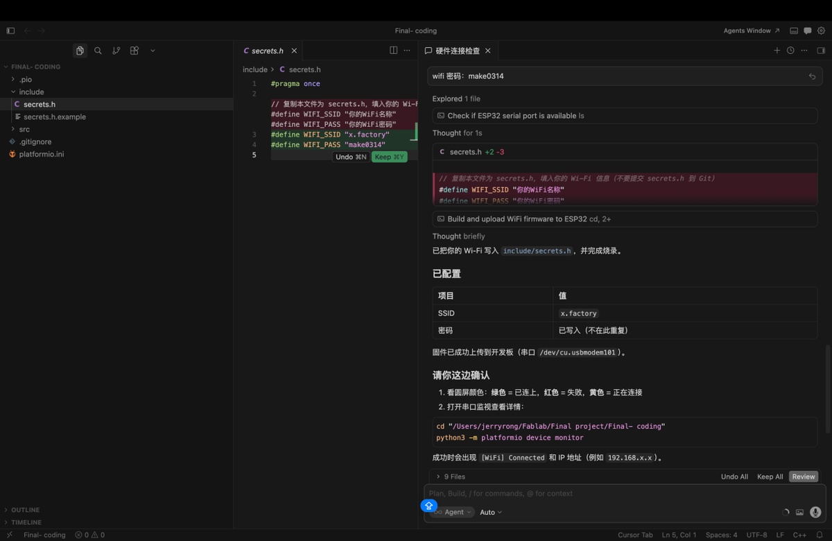
Connect the device to Wifi
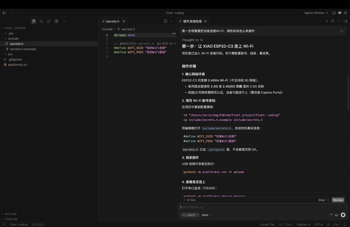
Provide the wifi account and code, to generate the firmware,and burn the firmware
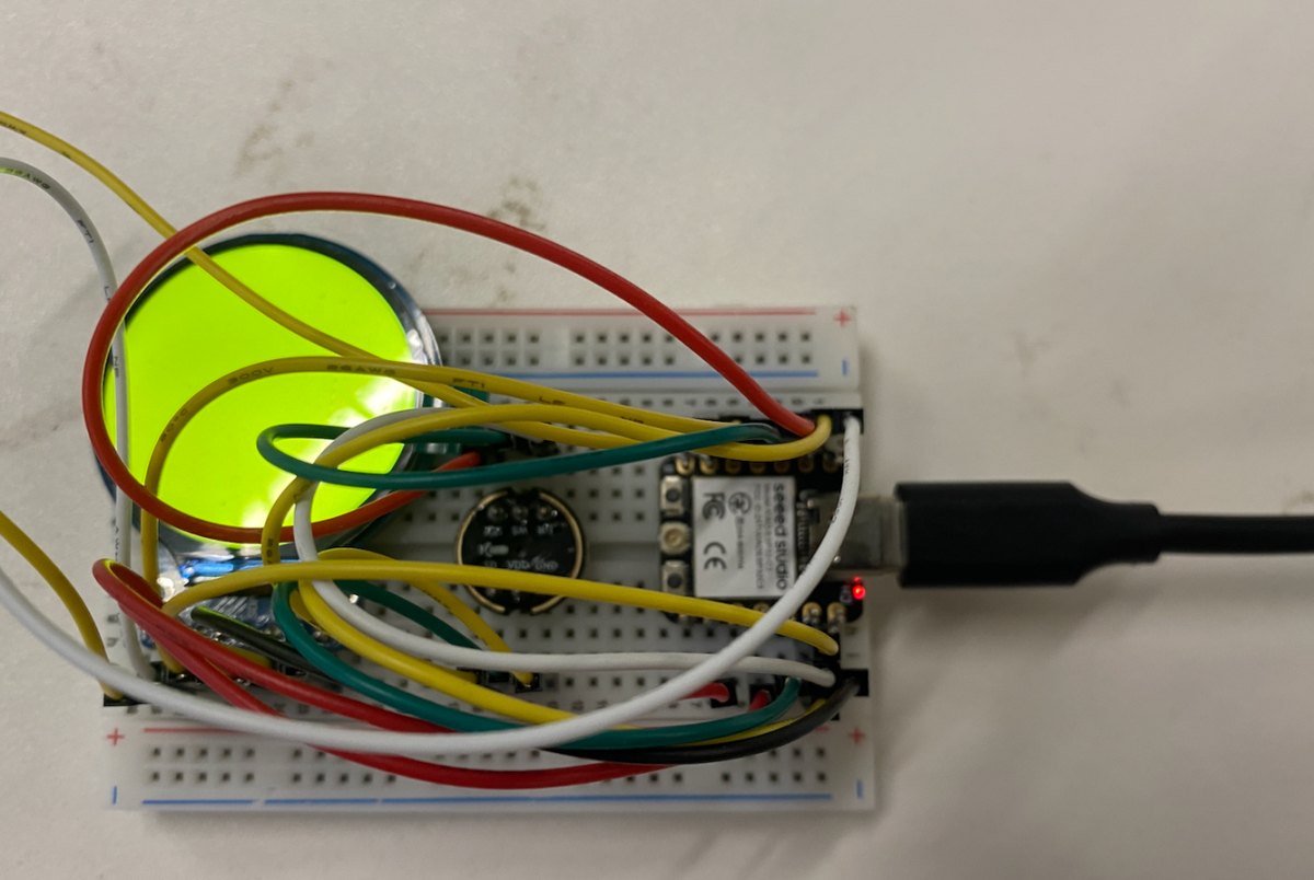
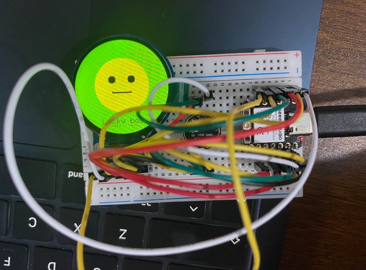
Testing :when the display show green means connected with wifi
Green: connected
Red: disconnected
Yellow: connecting
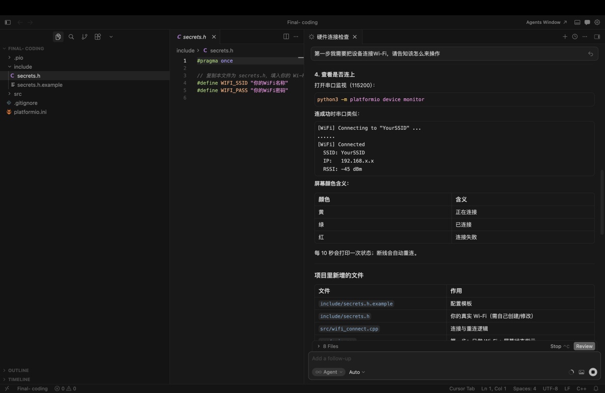
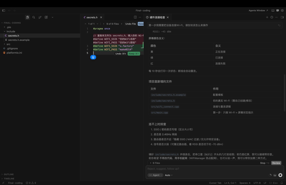
Key source code — WiFi connect + WiFi test (GC9A01 round LCD)
Early Wi-Fi hardware test on Seeed Xiao ESP32-C3 + GC9A01: round screen shows connection state by colour, Serial prints RSSI, auto-reconnect on disconnect.
The same wifi_connect module is reused in the full Lucky Bot firmware (main.cpp).
Project files: include/secrets.h, src/wifi_connect.cpp, src/gc9a01_hsd.cpp, src/main.cpp
| Screen colour | Meaning |
|---|---|
| Yellow | Connecting to Wi-Fi |
| Green | Connected (got IP) |
| Red | Disconnected / connect failed |
1. Wi-Fi credentials (include/secrets.h.example → copy to secrets.h):
#pragma once

#define WIFI_SSID "your_wifi_name"
#define WIFI_PASS "your_wifi_password"

// Mac LAN IP (terminal: ipconfig getifaddr en0)
#define ASR_SERVER_HOST "192.168.0.100"
#define ASR_SERVER_PORT 8765
2. Wi-Fi driver API (src/wifi_connect.h):
struct WiFiConnectResult {
  bool ok;
  int8_t rssi;
  IPAddress ip;
  const char* message;
};

void wifiInitSta();
bool wifiIsLinked();   // WL_CONNECTED + valid IP

WiFiConnectResult connectWiFi(const char* ssid, const char* password,
                              uint32_t timeoutMs = 45000);
void printWiFiStatus();  // SSID, IP, RSSI dBm
3. Wi-Fi connect function (src/wifi_connect.cpp):
WiFiConnectResult connectWiFi(const char* ssid, const char* password,
                              uint32_t timeoutMs) {
  WiFiConnectResult result = {false, 0, IPAddress(), "timeout"};
  if (!ssid || !ssid[0]) {
    result.message = "SSID empty — edit include/secrets.h";
    return result;
  }

  wifiInitSta();
  Serial.printf("[WiFi] Connecting to \"%s\" ...\n", ssid);

  // Scan hotspot first (helps iPhone hotspot — find channel + RSSI)
  int targetChannel = 0;
  const int found = WiFi.scanNetworks(false, true);
  for (int i = 0; i < found; i++) {
    if (WiFi.SSID(i) == ssid) {
      targetChannel = WiFi.channel(i);
      break;
    }
  }
  WiFi.scanDelete();

  WiFi.disconnect(false);
  delay(400);
  if (targetChannel > 0)
    WiFi.begin(ssid, password, targetChannel);
  else
    WiFi.begin(ssid, password);

  const uint32_t start = millis();
  while (!wifiIsLinked()) {
    if (WiFi.status() == WL_CONNECT_FAILED ||
        WiFi.status() == WL_NO_SSID_AVAIL) {
      result.message = "auth failed or SSID not found";
      return result;
    }
    if (millis() - start > timeoutMs) {
      result.message = "connection timeout";
      return result;
    }
    delay(400);
  }

  result.ok = true;
  result.rssi = WiFi.RSSI();
  result.ip = WiFi.localIP();
  printWiFiStatus();
  return result;
}
4. Wi-Fi test — colour screen + periodic status (early test main.cpp):
void showWifiColour(uint16_t color) { lcd.fillScreen(color); }

void setup() {
  lcd.begin();
  showWifiColour(COLOR_YELLOW);              // Yellow = connecting
  WiFiConnectResult r = connectWiFi(WIFI_SSID, WIFI_PASS);
  showWifiColour(r.ok ? COLOR_GREEN : COLOR_RED);
}

void loop() {
  if (wifiIsLinked()) {
    showWifiColour(COLOR_GREEN);
    printWiFiStatus();                       // e.g. RSSI: -45 dBm every 10 s
  } else {
    showWifiColour(COLOR_RED);
    connectWiFi(WIFI_SSID, WIFI_PASS);       // auto-reconnect
  }
}
Expected behaviour: power on → yellow → green + RSSI: -45 dBm → link lost → red → auto-reconnect.
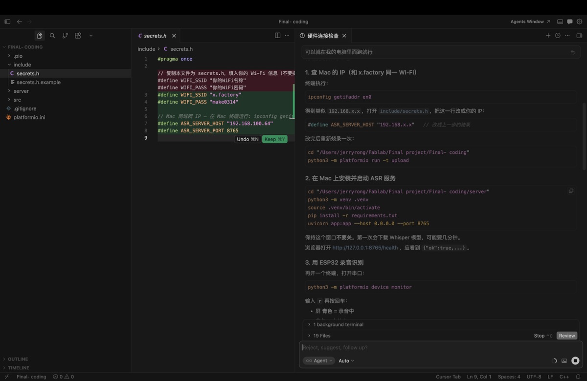
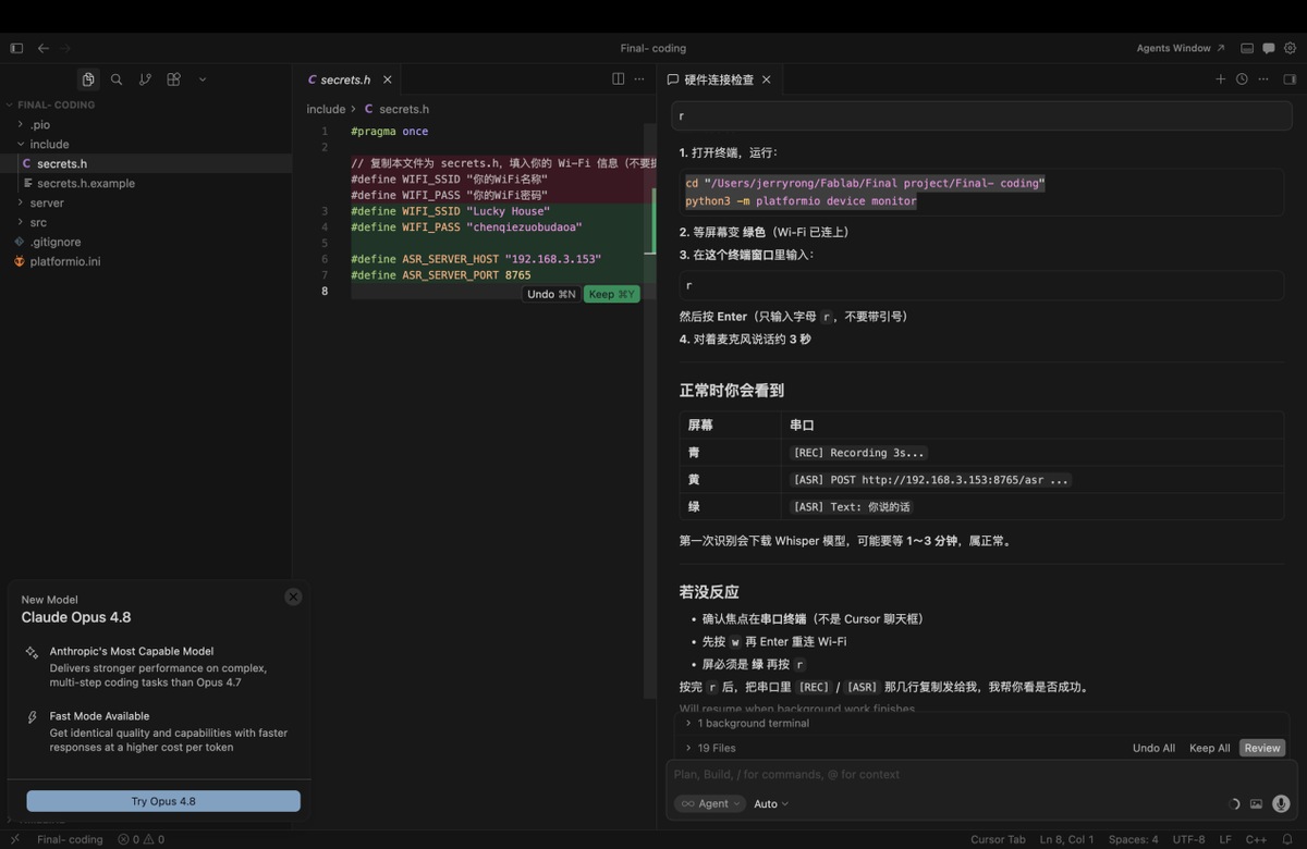
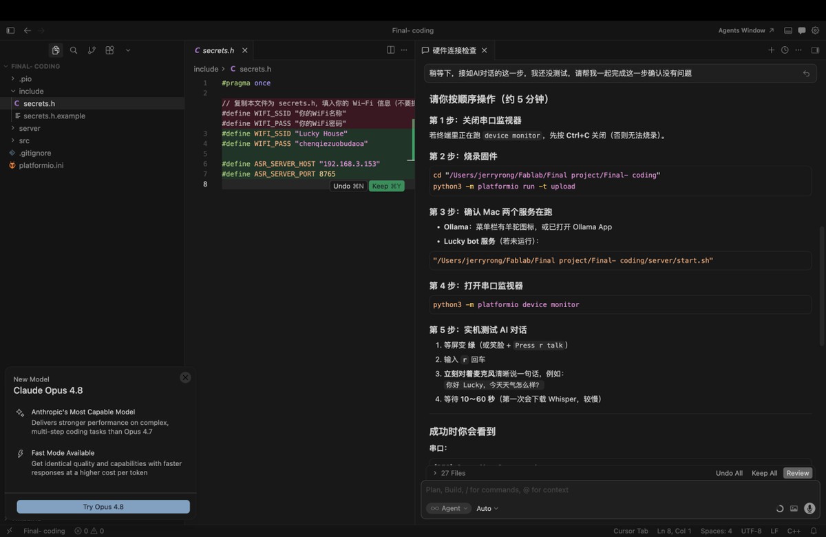
How to change the wifi configuration
Step 1: revise the information of Wifi in include/secrets.h
Step 2: burn the firmware again.
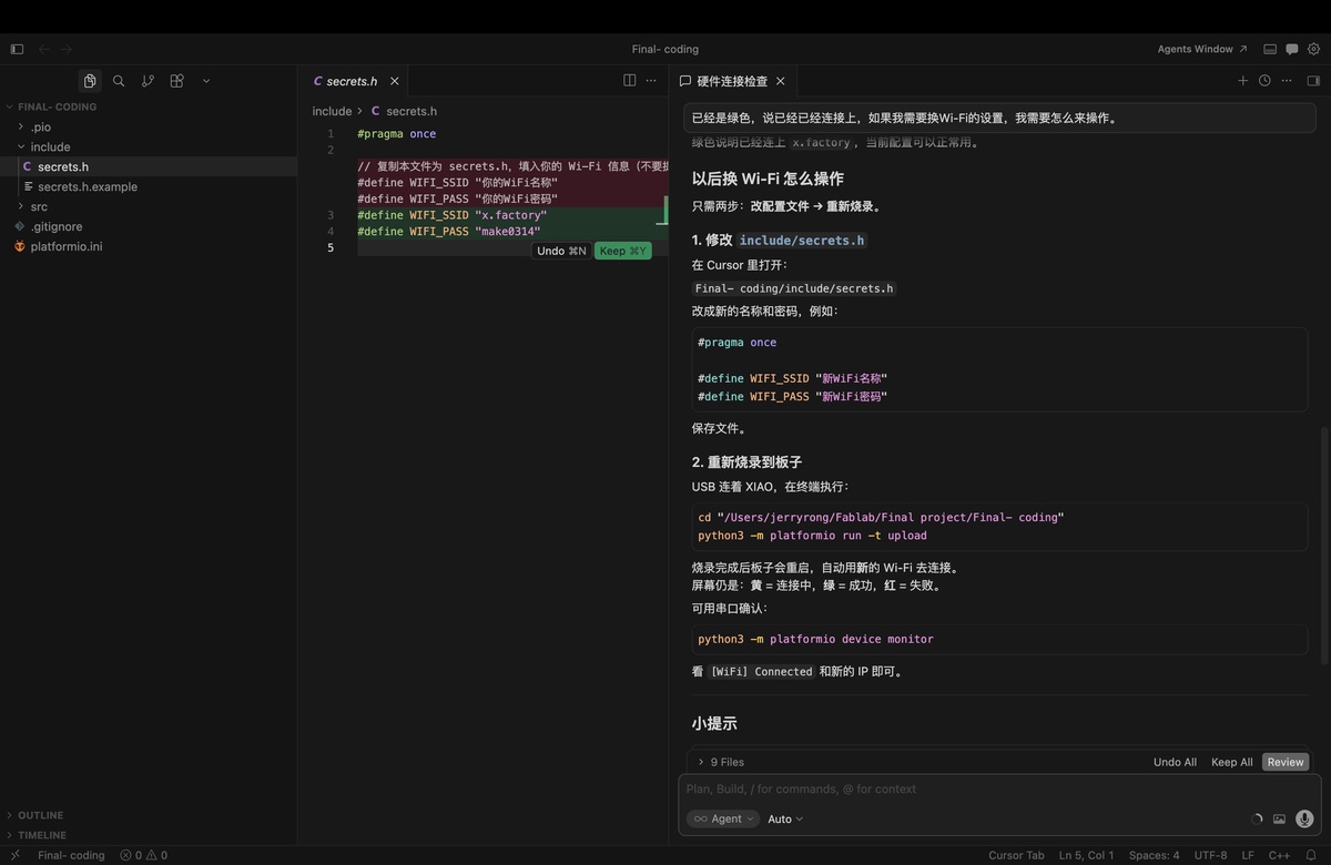
Edit Wi-Fi credentials (include/secrets.h — copy from secrets.h.example if needed):
#pragma once

#define WIFI_SSID "your_wifi_name"
#define WIFI_PASS "your_wifi_password"

#define ASR_SERVER_HOST "192.168.0.100"
#define ASR_SERVER_PORT 8765
Build, upload, and monitor (connect Xiao ESP32-C3 via USB first):
cd "/Users/jerryrong/Fablab/Final project/Final- coding"
python3 -m platformio run -t upload
python3 -m platformio device monitor
After re-flashing, check the round display: yellow = connecting, green = connected, red = failed.
Mic collect the audio and change it to text, with FunASR on cloud, and save the data to DB
Steps: 2.1 find out the IP address of the Mac.
2.2 install ASR on MAC and start the service
2.3 use ESP32-C3 to record voice and recognize
Key source code — ASR
1. ESP32 uploads WAV to Mac server (src/asr_client.cpp):
ChatResult uploadVoiceChat(const uint8_t* wav, size_t len, const char* host,
                           uint16_t port) {
  ChatResult result = {false, -1, 0, false, 0, 0, 0, "", "", ""};
  if (WiFi.status() != WL_CONNECTED) {
    result.error = "WiFi not connected";
    return result;
  }

  // POST audio/wav to http://<Mac-IP>:8765/chat
  int code = postWavChunked(host, port, wav, len, respBuf, sizeof(respBuf));
  if (code != 200) {
    result.error = String("HTTP ") + code;
    return result;
  }

  extractJsonString(respBuf, "text", userBuf, sizeof(userBuf));   // ASR result
  extractJsonString(respBuf, "reply", replyBuf, sizeof(replyBuf)); // AI reply
  result.userText = userBuf;
  result.reply = replyBuf;
  result.ok = true;
  return result;
}
2. Mac server — Whisper ASR (server/asr.py):
def transcribe_wav(data: bytes, *, language: str | None = "zh") -> tuple[str, str | None]:
    """Convert WAV bytes to text using OpenAI Whisper API or local faster-whisper."""
    use_openai = ASR_PROVIDER == "openai" and bool(ASR_API_KEY)
    if use_openai:
        return _transcribe_openai(data, language=language)
    return _transcribe_local(data, language=language)
3. Mac server — ASR API endpoint (server/app.py):
@app.post("/asr")
async def transcribe_only(request: Request) -> dict:
    """ASR only (no LLM). ESP32 sends WAV, Mac returns text."""
    data = await read_audio_bytes(request)
    user_text, language = await asyncio.to_thread(transcribe_wav, data)
    return {"text": user_text, "language": language}
Flow: ESP32 records audio (INMP441) → sends WAV via WiFi → Mac runs Whisper → text returned to serial monitor / web dashboard.
Testing
run the command in terminal
cd "/Users/jerryrong/Fablab/Final project/Final- coding"
python3 -m platformio device monitor
When the display show green means wifi connection is good.
In terminal, type r
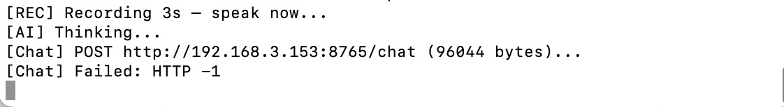
Start testing
| Light blue | [REC] Recording 3s... |
|---|---|
| yellow | [ASR] POST http://192.168.0.100:8765/asr... |
| green | [ASR] Text: the content I said |
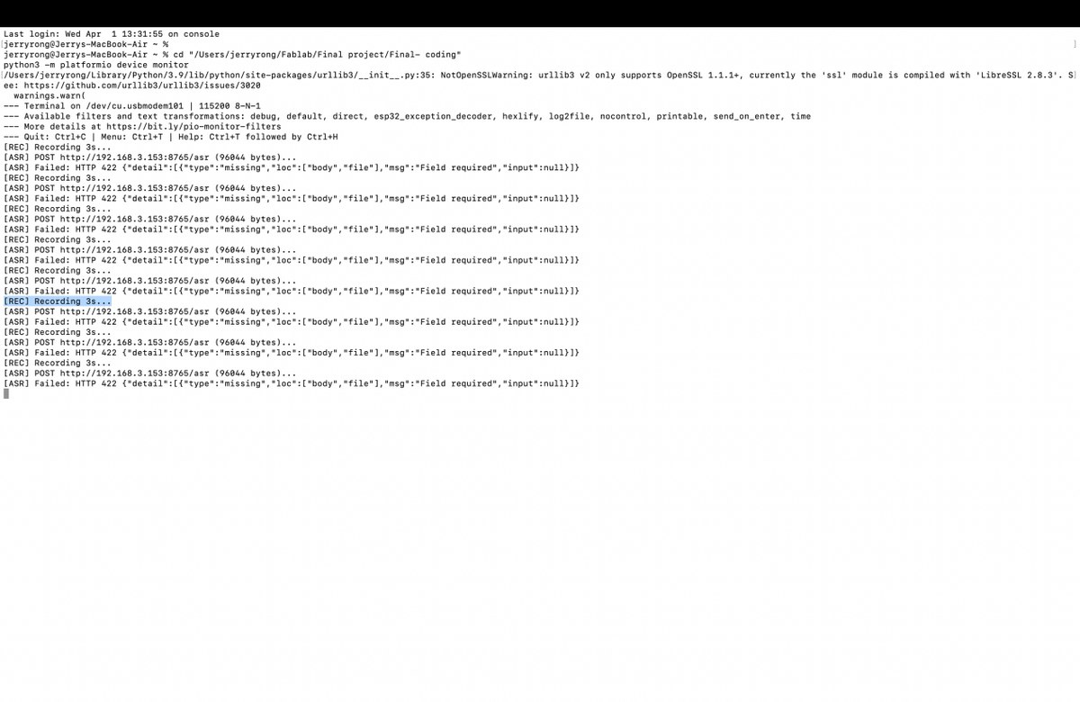
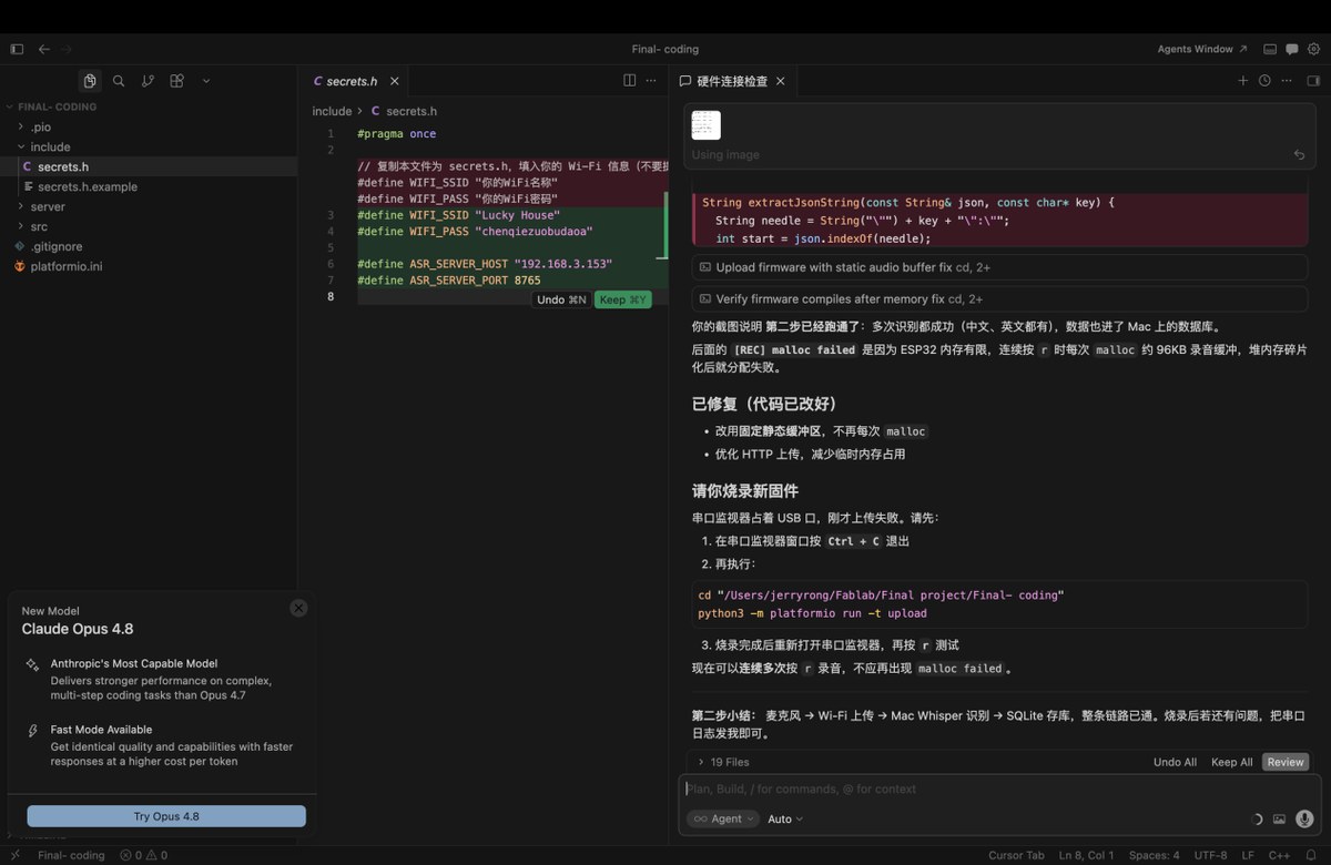
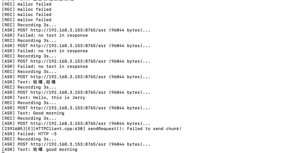
There is some error,iit didn’t turn out the content I said, so send the the image above to Cursor to debug。
It has been recovered but a new problem came, as below, “Malloc failed”
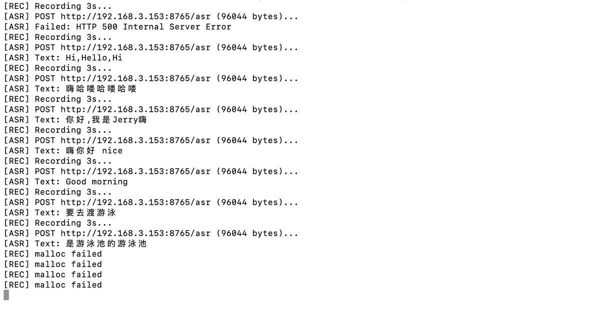
I send it to Cursor to debug again, I learned”Malloc Failed” means, there is no more storage. Cursor send me a new firmware and run it again.
It works again. Attach with video “ASR Testing”
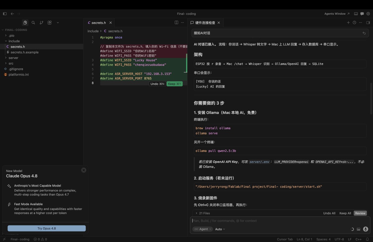
Connect AI for interactive communication, save the result to DB; I planned to use OpenAI API, Cursor suggest ollama, an open source tool to running LLM, more suitable for development, if Ollama didn’t run ideally, I can try OpenAI API. I follow the steps below,
3.1 install Ollama
3.2 Run Ollama and download Qwen2.5:3B LLM
3.3 burn the new firmware
3.4 check result, there will be 2 roles in the Terminal
Ollama and Qwen 2.5:3B model has been installed
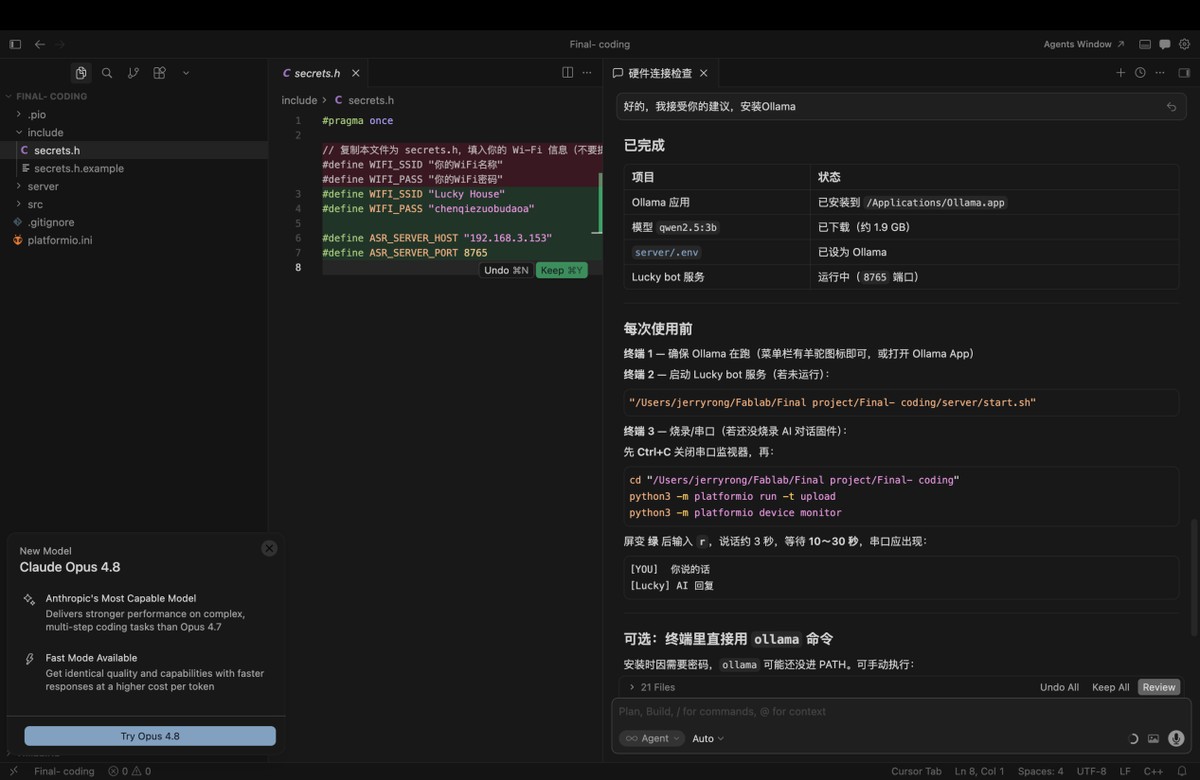
Run testing, to make sure the step works well,follow the steps below
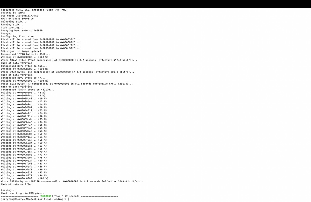
Close serial monitor in Terminal, ctrl + c
Burn new firmware:
cd "/Users/jerryrong/Fablab/Final project/Final- coding"
python3 -m platformio run -t upload
Make sure Ollama and Lucky Bot is working, Ollama is already opening, and I used ,http://127.0.0.1:8765/health to check the status on browser
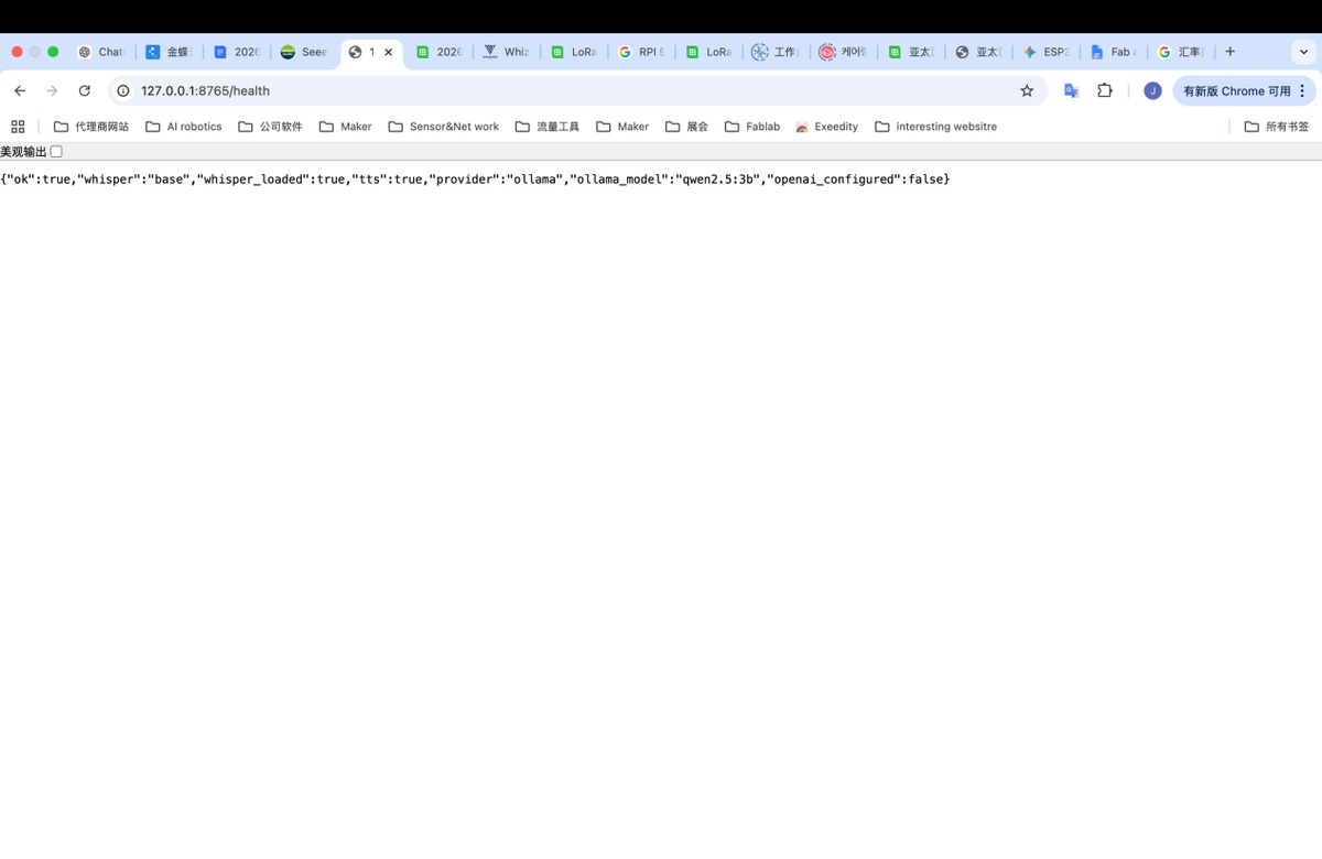
Open serial monitor with command below,
python3 -m platformio device monitor
Talk with the Lucky Bot, check if it works, but It didn’t run well, show error
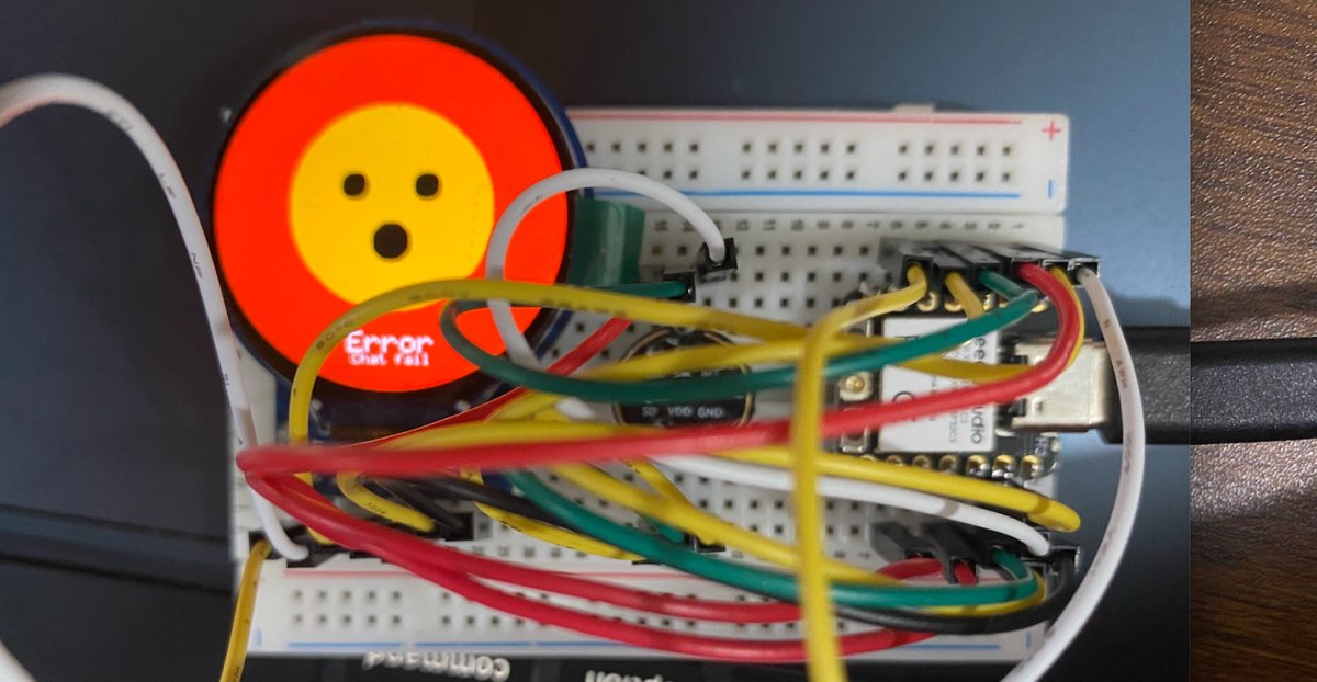
I debug with cursor on the issue, all connection is running good, but there is router AP isolation.
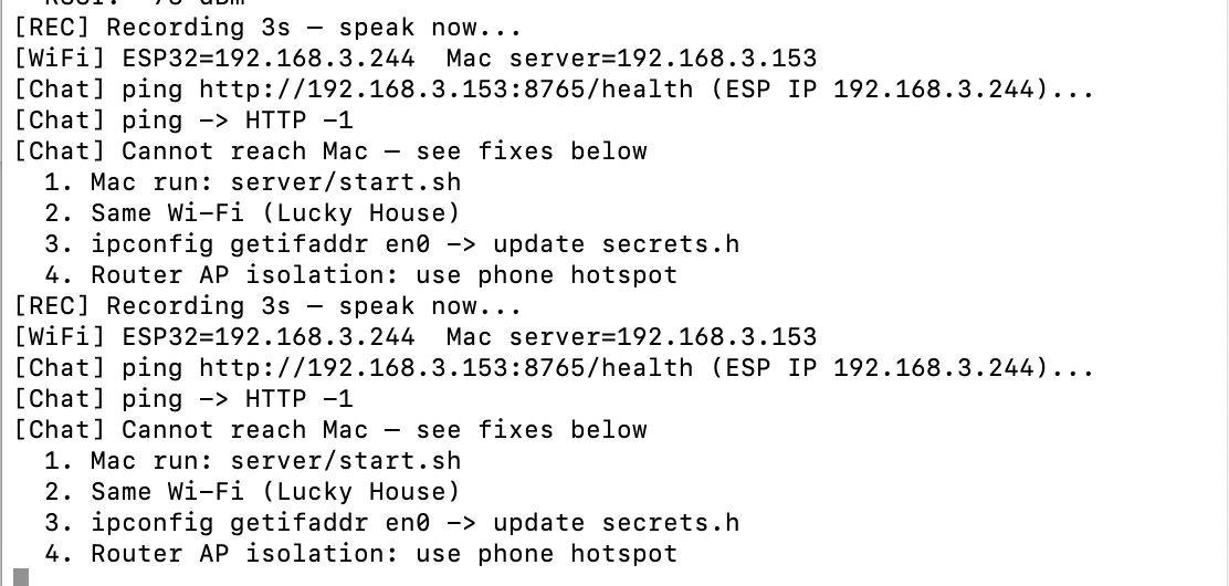
I will going to change the network to my iphone hotspot, same as above, mac and esp32 connect with my iphone, configure the wifi to ESP32, finally solve the problem, it start running, output the audio from my Mac, video as below , video file - AI connection+ voice bot testing
Key source code — LLM (Ollama / OpenAI)
Mac server runs Ollama + Qwen2.5:3B locally (or switches to OpenAI-compatible API). ESP32 sends transcribed text via /chat; Mac returns AI reply + TTS.
Project files: server/llm.py, server/app.py, server/.env.example
1. LLM provider config (server/.env.example — copy to .env, never commit real keys):
LLM_PROVIDER=ollama
OLLAMA_URL=http://127.0.0.1:11434
OLLAMA_MODEL=qwen2.5:3b

# Optional cloud fallback:
# LLM_PROVIDER=openai
# OPENAI_API_KEY=sk-your-key-here
# OPENAI_MODEL=gpt-4o-mini
2. Chat function (server/llm.py):
def chat(messages: list[dict[str, str]]) -> str:
    if LLM_PROVIDER == "openai":
        if not OPENAI_API_KEY:
            raise RuntimeError("OPENAI_API_KEY not set in server/.env")
        return _chat_openai(messages)
    return _chat_ollama(messages)

def _chat_ollama(messages: list[dict[str, str]]) -> str:
    payload = {"model": OLLAMA_MODEL, "messages": messages, "stream": False}
    req = urllib.request.Request(
        f"{OLLAMA_URL}/api/chat",
        data=json.dumps(payload).encode("utf-8"),
        headers={"Content-Type": "application/json"},
        method="POST",
    )
    # ... parse message.content from Ollama response ...
3. Voice chat endpoint (server/app.py):
@app.post("/chat")
async def voice_chat(request: Request) -> dict:
    """ESP32 uploads WAV → ASR → LLM reply → save DB → TTS."""
    data = await read_audio_bytes(request)
    user_text, language = await asyncio.to_thread(transcribe_wav_with_fallback, data)
    messages = load_chat_history()
    messages.append({"role": "user", "content": user_text})
    ai_reply = await asyncio.to_thread(chat, messages)
    turn_id = save_chat_turn(user_text, ai_reply)
    return {"text": user_text, "reply": ai_reply, "turn_id": turn_id, "tts_ms": tts_ms}
Expected behaviour: ESP32 uploads WAV → Mac transcribes → Qwen generates reply → serial shows [YOU] / [Lucky] → Mac speaker plays TTS.
Update on 30th, May
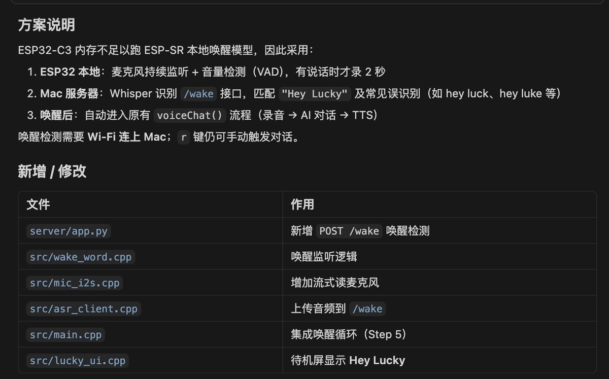
Wake-up words, I will use “ Hey Lucky”
Prompt: I wanna setting the keyword” Hey Lucky”
Cursor: provide a solution:
Mic continuous monitoring + VAD
Whisper recognition, match “ Hey Lucky”
After waking up, it goes to voice chat (recording - AI conversation -TTS)
I got a firmware from cursor with command below, I will flash to ESP32 in terminal
cd "/Users/jerryrong/Fablab/Final project/Final- coding"
python3 -m platformio run -t upload
python3 -m platformio device monitor
When I say “ Hey Lucky” it has been detected, but there is new problem as below,
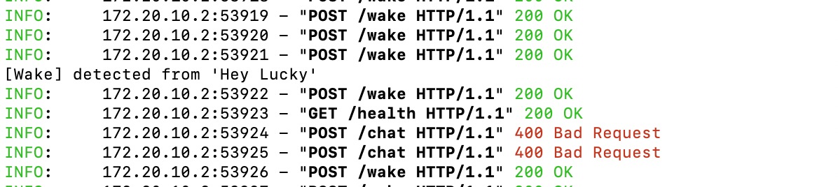
I sent the picture to debug and got the reason and new firmware
Reason: After detecting the wake word, recording starts immediately for 3 seconds, but by then you've usually already finished saying "Hey Lucky," so most of what's recorded is silence. Whisper can't recognize any content, and the server returns a 400 error
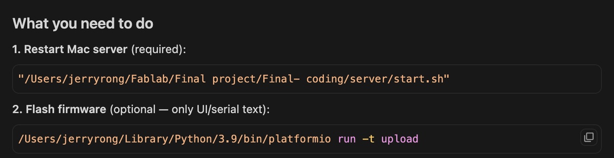
New firmware:
/Users/jerryrong/Library/Python/3.9/bin/platformio run -t upload
And restart the mac server:
"/Users/jerryrong/Fablab/Final project/Final- coding/server/start.sh"
It runs good, see the video attached ( Wake-up word, Hey Lucky)
But I feel it is not sensitive enough, sometimes I need to call him 2 or 3 times, and the transition time, from waking up to listening, I has cursor to improve
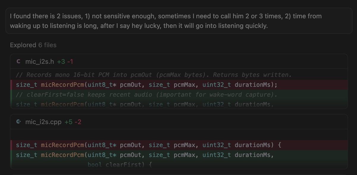
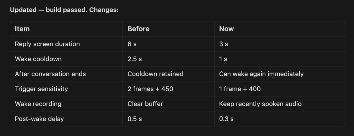
Cursor find out the reason and provide the new firmware:
/Users/jerryrong/Library/Python/3.9/bin/platformio run -t upload
With new setting
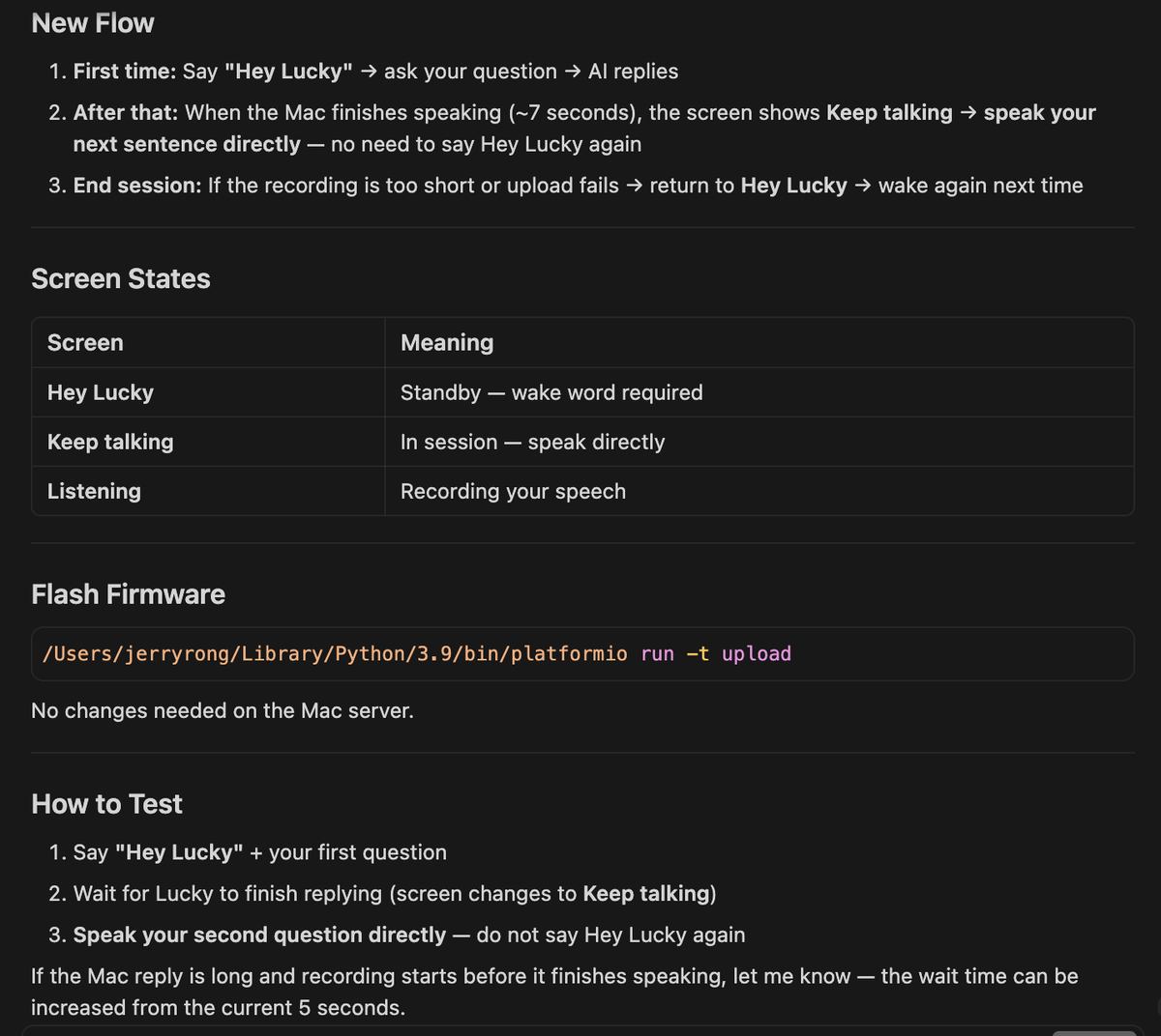
I find a new issue, the bot should be continue to talk after the first wake up, no need to wake up every time when we are in communication.
New firmware:
/Users/jerryrong/Library/Python/3.9/bin/platformio run -t upload
There is a new issue happen, I need a continuous conversation, but the mic will collect the reply of the AI bot, so it will reply again, no any time for you to talk with the bot, bot never stop talking. Cursor fix the problem with a new Firmware and update the server
firmware
/Users/jerryrong/Library/Python/3.9/bin/platformio run -t upload
Update server:
"/Users/jerryrong/Fablab/Final project/Final- coding/server/start.sh"
I got a good interaction experience, see the video attached (bot continuous communication)
Key source code — wake word ("Hey Lucky" / "Hi Lucky" / "Lucky")
ESP32 continuously monitors mic RMS; on speech it captures a short WAV clip and POSTs to Mac /wake. Mac runs Whisper Tiny to match wake phrases, then opens a continuous session (no re-wake between turns).
Project files: src/wake_word.cpp, src/asr_client.cpp, server/app.py, include/lucky_config.h
1. Wake detection config (include/lucky_config.h):
constexpr uint32_t kWakePreRollMs = 500;       // keep start of "Hey/Hi"
constexpr uint32_t kWakeClipMs = 1800;         // max clip sent to Mac
constexpr int32_t kWakeRmsThreshold = 200;     // lower = more sensitive
constexpr uint32_t kWakeSpeechFramesNeeded = 2;  // ~40 ms above threshold
constexpr uint32_t kSessionWaitMs = 12000;     // no speech → back to standby
2. ESP32 — poll mic + upload clip (src/wake_word.cpp):
bool wakePoll(const char* host, uint16_t port) {
  const int32_t rms = frameRms(frameBuf, got);
  if (rms < kWakeRmsThreshold) return false;

  if (!captureWakeClip()) return false;
  const WakeResult result = checkWakeWord(wakeWav, wakeWavLen, host, port);

  if (result.detected) {
    Serial.println("[Wake] Wake word detected!");
    wakeMuteUntil = millis() + kWakeAfterDetectCooldownMs;
    return true;
  }
  return false;
}
3. POST clip to Mac (src/asr_client.cpp):
WakeResult checkWakeWord(const uint8_t* wav, size_t len, const char* host, uint16_t port) {
  const int code = postWavToPath("/wake", host, port, wav, len, respBuf, sizeof(respBuf));
  extractJsonString(respBuf, "text", textBuf, sizeof(textBuf));
  extractJsonBool(respBuf, "detected", &detected);
  result.detected = detected;
  return result;
}
4. Mac — phrase matching (server/app.py):
@app.post("/wake")
async def wake_word(request: Request) -> dict:
    data = await read_audio_bytes(request)
    text, language = await asyncio.to_thread(transcribe_wake_clip, data)
    detected = is_wake_phrase(text)  # Hey Lucky, Hi Lucky, Lucky, 荣幸
    return {"ok": True, "detected": detected, "text": text, "language": language}

def is_wake_phrase(text: str) -> bool:
    lower = normalize_wake_text(text).lower()
    for marker in ("hey lucky", "hi lucky", "hey luck", "hi luck"):
        if marker in lower:
            return True
    # ... standalone "lucky", Chinese 荣幸 variants ...
    return False
Expected behaviour: say "Hey Lucky" → [Wake] detected → Mac plays wake SFX → records your question → continuous session until 12 s silence.
I feel I can add 2 more waking up words , Hi Lucky and Lucky
I found there is too many details need to improve, spent several hours but no obvious Progress, I found a important issue, as no experience, I found the problem is by random, as I didn’t make a request list to Ai first. Therefore, In future, I’d better list the request first.
Web/Platform design
Basic functions:
1) Need a switch to enable the Mac server at once (Cursor suggests if this is necessary)
2) Need a status bar to display the Wi-Fi connection status of the ESP32 and the Wi-Fi connection
3) Need a box to display the text content as mentioned, and another box to display
4) Need a status bar, speaking (display when a person is speaking), thinking (display when the AI bot is thinking)
5) Overall page style, Apple style
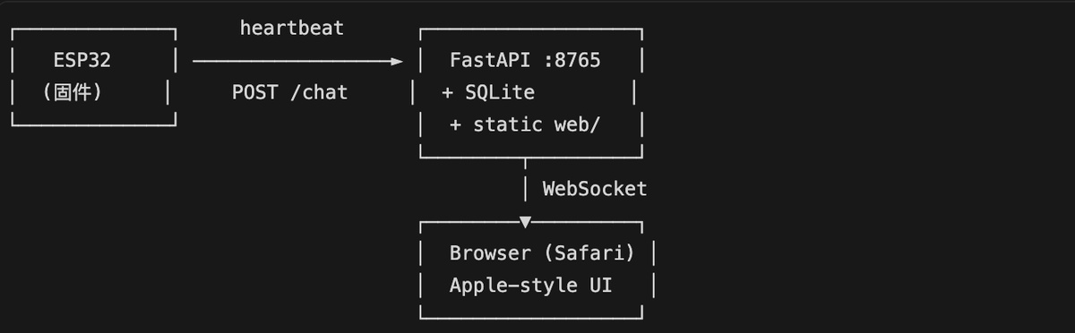
Gemini give me the diagram
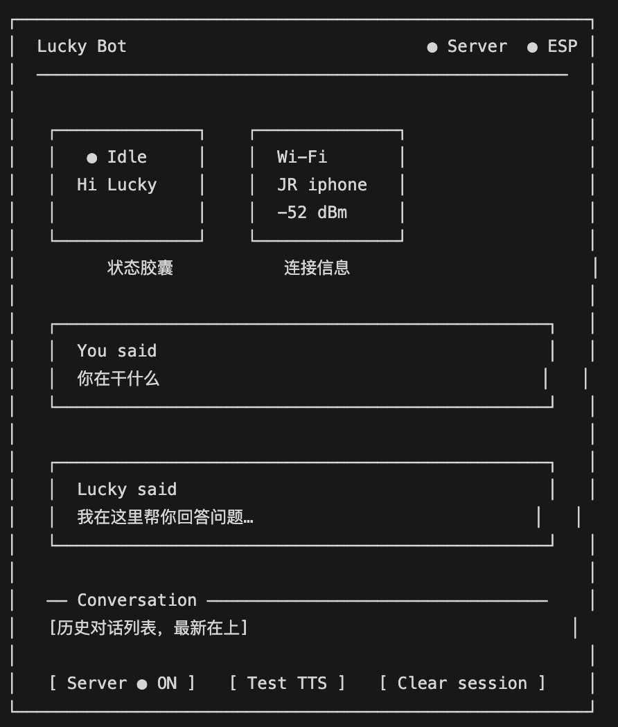
The first version
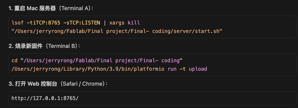
Open Mac server again
lsof -tiTCP:8765 -sTCP:LISTEN | xargs kill
"/Users/jerryrong/Fablab/Final project/Final- coding/server/start.sh"
Flash New firmware
cd "/Users/jerryrong/Fablab/Final project/Final- coding"
/Users/jerryrong/Library/Python/3.9/bin/platformio run -t upload
Web to check
Launching website: http://127.0.0.1:8764/
Web: http://127.0.0.1:8765/
Video show how does it work
Optimization:
I need button to turn on the Mac server
change the Icon of the Robot
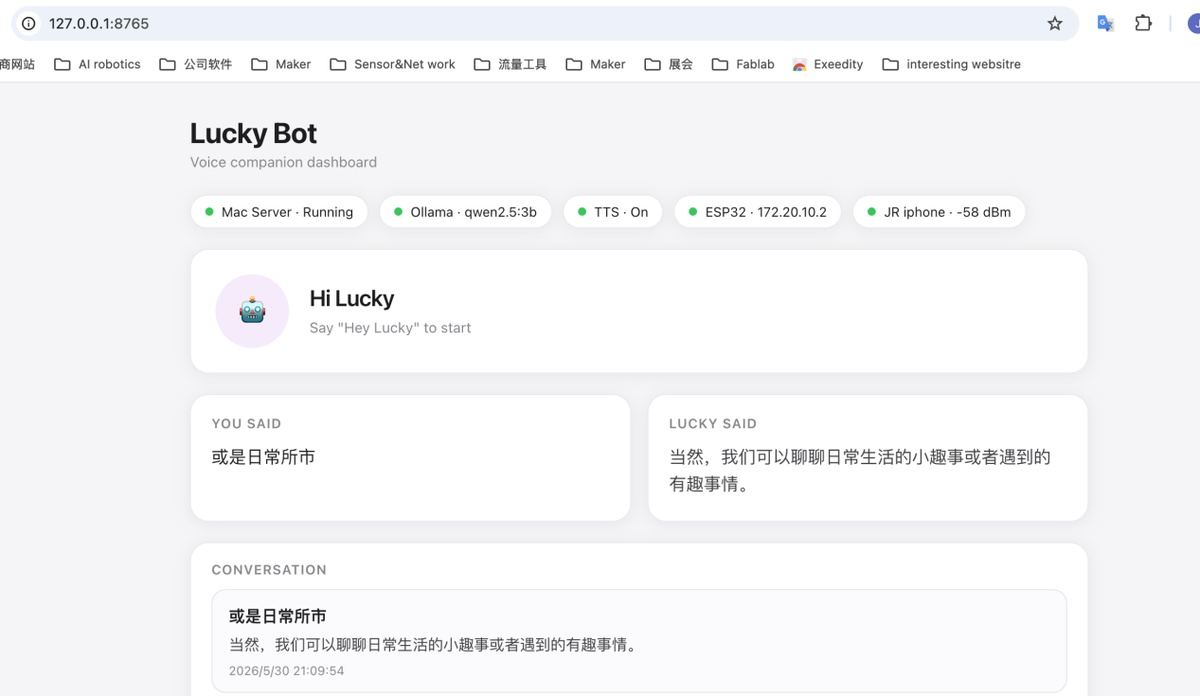
Key source code — Web UI (Lucky Bot dashboard)
Browser dashboard on Mac: Start Server button (no Terminal), custom Lucky avatar, live ESP32 status, conversation history.
Project files: server/web/control.html, server/web/index.html, server/launcher.py, server/app.py, server/hub.py
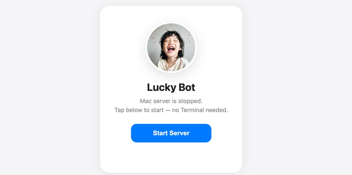
1. Start page + Start Server button (server/web/control.html):
<div class="card">
  <div class="avatar-wrap">
    <img src="/avatar.png" alt="Lucky" />
  </div>
  <h1>Lucky Bot</h1>
  <p>Mac server is stopped. Tap below to start — no Terminal needed.</p>
  <button id="btn-start" type="button">Start Server</button>
</div>
<script>
  btn.addEventListener("click", async () => {
    const r = await fetch("/server/start", { method: "POST" });
    const j = await r.json();
    if (j.running) location.href = "http://127.0.0.1:8765/";
  });
</script>
Replace server/web/avatar.png with your own photo to change the robot icon.
2. Launcher — start/stop Mac server on :8764 (server/launcher.py):
MAIN_PORT = 8765  # main FastAPI app (dashboard + ASR)

@app.get("/")
def root():
    if _main_healthy():
        return RedirectResponse(f"http://127.0.0.1:{MAIN_PORT}/")
    return FileResponse(WEB_DIR / "control.html")  # Start Server page

@app.post("/server/start")
def server_start() -> dict:
    if _main_healthy():
        return {"ok": True, "running": True}
    _ensure_ollama()
    subprocess.Popen(["uvicorn", "app:app", "--host", "0.0.0.0", "--port", str(MAIN_PORT)], ...)
    # poll /health until ready
    return {"ok": True, "running": True}

@app.get("/avatar.png")
def avatar():
    return FileResponse(WEB_DIR / "avatar.png")
Run once: ./launcher.sh → open http://127.0.0.1:8764/
3. Dashboard layout (server/web/index.html):
<div class="pill-row">
  <div class="pill"><span class="dot" id="dot-server"></span><span id="lbl-server">Lucky</span></div>
  <div class="pill"><span class="dot" id="dot-llm"></span><span id="lbl-llm">LLM</span></div>
  <div class="pill"><span class="dot" id="dot-tts"></span><span id="lbl-tts">TTS</span></div>
  <div class="pill"><span class="dot" id="dot-esp"></span><span id="lbl-esp">ESP32</span></div>
  <div class="pill"><span class="dot" id="dot-wifi"></span><span id="lbl-wifi">Wi-Fi</span></div>
</div>

<section class="status-hero">
  <div class="status-ring" id="status-ring">
    <img src="/avatar.png" alt="Lucky" class="avatar" />
  </div>
  <div class="status-label" id="status-label">Offline</div>
</section>

<div class="grid-2">
  <div class="card user"><h2>You said</h2><div id="you-said">—</div></div>
  <div class="card bot"><h2>Lucky said</h2><div id="lucky-said">—</div></div>
</div>

<button id="btn-server">Start Talking</button>
4. Live status rendering (JavaScript in index.html):
const STATE_LABELS = {
  offline: "Offline", ready: "Ready", wake_listen: "Hi Lucky",
  listening: "Listening", thinking: "Thinking", speaking: "Speaking",
};

function renderDashboard(data) {
  const server = data.server || {};
  const dev = data.device || {};
  const state = dev.online ? dev.state : "offline";

  setDot($("dot-server"), !!server.ok);
  setDot($("dot-esp"), !!dev.online);
  setDot($("dot-wifi"), dev.online && dev.wifi_connected);

  $("status-label").textContent = STATE_LABELS[state] || state;
  $("status-ring").className = "status-ring " + state;

  const chat = data.latest_chat;
  if (chat) {
    $("you-said").textContent = chat.user;
    $("lucky-said").textContent = chat.reply;
  }
  renderHistory(data.history);
}
5. Start/Stop server from dashboard:
async function toggleServer() {
  const st = await fetch("http://127.0.0.1:8764/server/status").then(r => r.json());
  const path = st.running ? "/server/stop" : "/server/start";
  await fetch("http://127.0.0.1:8764" + path, { method: "POST" });
  fetchDashboard();
}
6. Real-time updates — WebSocket:
function connectWs() {
  const ws = new WebSocket(`ws://${location.host}/ws`);
  ws.onmessage = (ev) => {
    const msg = JSON.parse(ev.data);
    if (msg.type === "init") renderDashboard(msg.data);
    if (msg.type === "device" || msg.type === "chat") fetchDashboard();
  };
  ws.onclose = () => setTimeout(connectWs, 2000);
}
7. Backend API (server/app.py):
@app.get("/")
def dashboard():
    return FileResponse(WEB_DIR / "index.html")

@app.get("/api/dashboard")
def api_dashboard(limit: int = 20):
    return {"server": health(), **dashboard_snapshot(), "history": chat_history(limit)}

@app.post("/device/status")
async def post_device_status(request: Request):
    update_device(await request.json())  # ESP32 heartbeat
    schedule_broadcast({"type": "device", "data": device_snapshot()})

@app.websocket("/ws")
async def websocket_endpoint(ws: WebSocket):
    await ws.accept()
    await ws.send_json({"type": "init", "data": {...dashboard_snapshot()...}})
8. Device state hub (server/hub.py):
def update_device(payload: dict) -> DeviceStatus:
    dev.state = str(payload.get("state") or "offline")  # listening, thinking, ...
    dev.ssid = str(payload.get("ssid") or "")
    dev.ip = str(payload.get("ip") or "")
    dev.updated_at = time.time()
    return dev

def device_snapshot() -> dict:
    online = (time.time() - dev.updated_at) < DEVICE_OFFLINE_SEC
    return {"online": online, "state": dev.state, "ssid": dev.ssid, "ip": dev.ip}
Expected behaviour: open http://127.0.0.1:8764/ → tap Start Server → dashboard at :8765 shows Lucky avatar, status pills, and conversation; ESP32 POSTs /device/status → Web UI updates in real time.
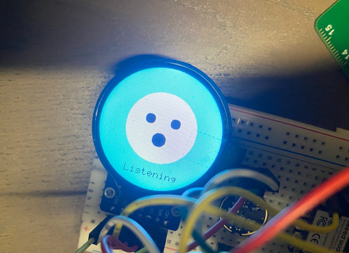
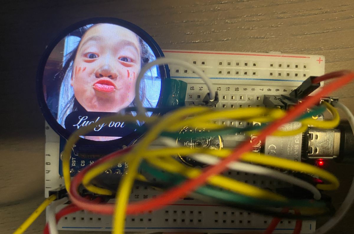
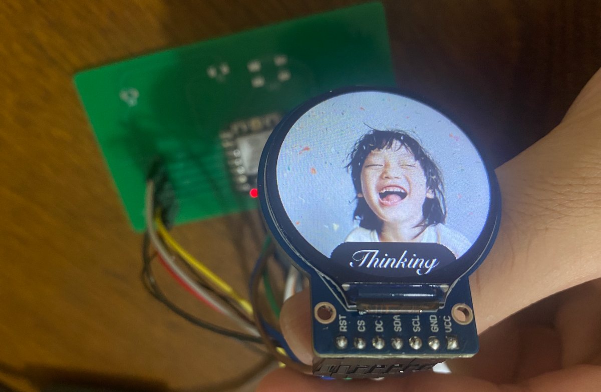
Display UI
My Idea:
Use my own image
The text will be displayed in the screen with text, but the style is Chinese cursive script
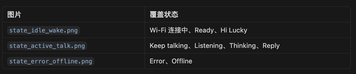
For Image, I will use three image to cover all the 9 states
The current setting with some image generated by Code, as below
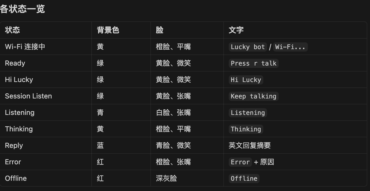
I sent the image to Cursor, and require the status and the images, different status with different image,
I got the initial firmware and burn it to ESP32
cd "/Users/jerryrong/Fablab/Final project/Final- coding"
/Users/jerryrong/Library/Python/3.9/bin/platformio run -t upload
UI has been updated, and Testing as the video( file “UI”)
I did some other optimization on the UI to make sure the status is closer to daily use. For example, show Wi-Fi disconnection status and maintain that UI for a long time until connected again.
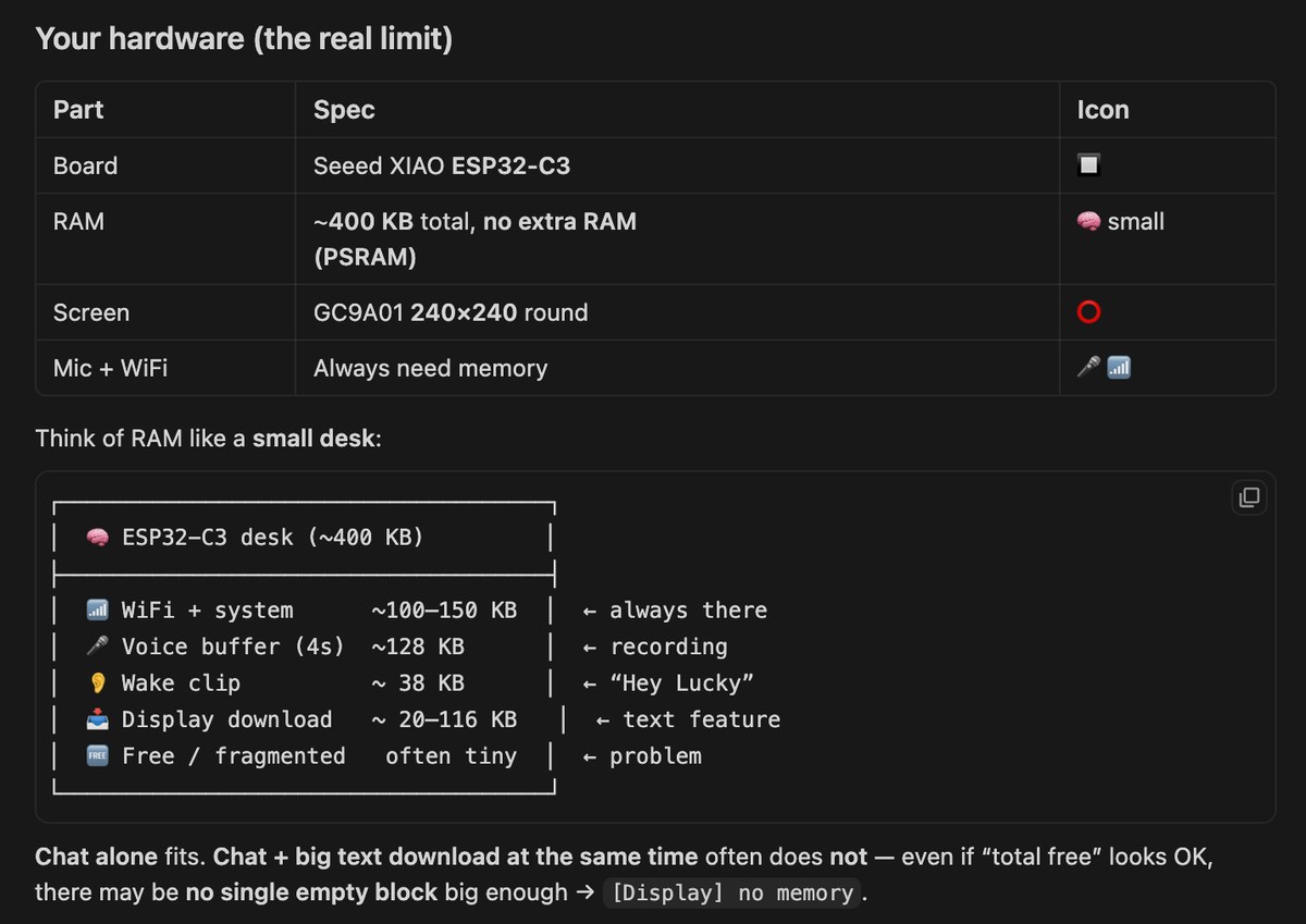
For the text showing on the display, it is very hard for the Xiao ESP32-C3, as there is no SRAM like the Xiao S3. I had to give up this function.
Key source code — Display UI (GC9A01 round LCD)
240×240 round LCD on Seeed Xiao ESP32-C3: three pre-rendered background images + cursive-style label bitmaps for 9 states.
Chinese reply glyphs on screen (display_anim) are disabled on C3 — not enough SRAM vs Xiao S3.
Project files: src/lucky_ui.cpp, src/gc9a01_hsd.cpp, src/generated/display_bitmaps.h, tools/gen_display_assets.py
1. Screen states (src/lucky_ui.h):
enum class LuckyScreen {
  kWifiConnect,   // connecting Wi-Fi
  kReady,         // idle — "Press r talk"
  kWakeListen,    // "Hi Lucky"
  kWakeAck,       // wake acknowledged
  kSessionListen, // continuous session
  kListening,
  kReplying,
  kThinking,
  kReply,
  kError,
  kOffline,       // Wi-Fi lost — held until reconnect
};

class LuckyUI {
 public:
  void show(LuckyScreen screen, const char* line1 = "", const char* line2 = "");
};
2. Three backgrounds + label overlays (src/lucky_ui.cpp):
#include "generated/display_bitmaps.h"

void LuckyUI::show(LuckyScreen screen, const char* line1, const char* line2) {
  switch (screen) {
    case LuckyScreen::kWifiConnect:
      lcd_.drawRGB565Bitmap(0, 0, 240, 240, BMP_IDLE_WAKE_DATA);
      drawLabelPair(LBL_LUCKY_BOT, LBL_WIFI);          // "Lucky bot" + "Wi-Fi…"
      break;

    case LuckyScreen::kReady:
    case LuckyScreen::kWakeListen:
      lcd_.drawRGB565Bitmap(0, 0, 240, 240, BMP_IDLE_WAKE_DATA);
      drawLabelPair(LBL_LUCKY_BOT, LBL_HI_LUCKY);      // idle / wake listen
      break;

    case LuckyScreen::kListening:
    case LuckyScreen::kThinking:
    case LuckyScreen::kReplying:
      lcd_.drawRGB565Bitmap(0, 0, 240, 240, BMP_ACTIVE_TALK_DATA);
      drawLabel(LBL_LISTENING);                        // or THINKING / REPLYING
      break;

    case LuckyScreen::kOffline:
    case LuckyScreen::kError:
      lcd_.drawRGB565Bitmap(0, 0, 240, 240, BMP_ERROR_OFFLINE_DATA);
      drawLabel(LBL_OFFLINE);                          // held until Wi-Fi returns
      break;
  }
}
3. Generate bitmap assets from photos + cursive labels (tools/gen_display_assets.py):
LABELS = {
    "lucky_bot": "Lucky bot", "wifi": "Wi-Fi…", "hi_lucky": "Hi Lucky",
    "listening": "Listening", "thinking": "Thinking", "offline": "Offline",
}
BACKGROUNDS = {
    "bmp_idle_wake": "state_idle_wake.png",       # states 1–3
    "bmp_active_talk": "state_active_talk.png",   # states 4–8
    "bmp_error_offline": "state_error_offline.png",
}
# Renders 240×240 RGB565 → src/generated/display_bitmaps.h (PROGMEM)
Run: python3 tools/gen_display_assets.py
4. LCD driver — blit full-screen bitmap (src/gc9a01_hsd.cpp):
bool GC9A01_HSD::begin() {
  // SPI pins D0/D4/D5/D8/D10, HSD vendor init sequence
  spi_.begin(PIN_LCD_SCK, -1, PIN_LCD_MOSI, -1);
  runHsdInit();
  return true;
}

void GC9A01_HSD::drawRGB565Bitmap(int x, int y, int w, int h,
                                  const uint16_t* data, uint16_t transparent) {
  setAddrWindow(x, y, x + w - 1, y + h - 1);
  for (int i = 0; i < w * h; i++) {
    if (data[i] != transparent) pushColor(data[i], 1);
  }
}
5. Wi-Fi disconnect — keep Offline UI until reconnect (src/main.cpp):
if (!wifiIsLinked()) {
  if (screenState != LuckyScreen::kOffline) {
    ui.show(LuckyScreen::kOffline);
    screenState = LuckyScreen::kOffline;
  }
  connectWiFi(WIFI_SSID, WIFI_PASS);   // retry in loop
  return;
}
6. State changes during voice chat:
ui.show(LuckyScreen::kListening);
// ... micRecordUntilSilence + upload ...
ui.show(LuckyScreen::kThinking);
// ... wait for Mac reply + TTS ...
ui.show(LuckyScreen::kReplying);
ui.show(LuckyScreen::kWakeListen);     // back to standby
7. Chinese cursive reply on screen — disabled on C3 (include/lucky_config.h):
constexpr bool kEnableReplyDisplay = false; // Scheme A off — ESP32-C3 RAM too small
When enabled, Mac renders glyphs (server/display_text.py) and ESP downloads via display_anim.cpp — needs ~116 KB buffer; C3 has no PSRAM, so pre-rendered label bitmaps only.
Expected behaviour: power on → idle photo + "Wi-Fi…" → ready → "Hi Lucky" → active photo + "Listening/Thinking" → Wi-Fi drops → offline photo stays until reconnect.
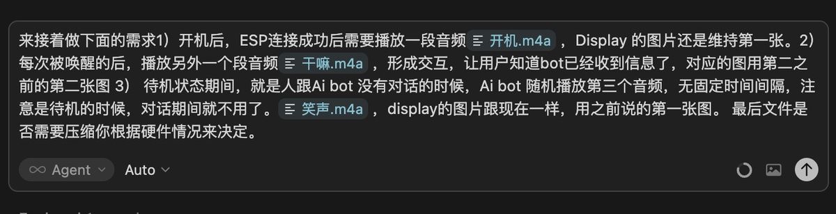
Update on 31st, May
Add voice interaction.
My Idea:
1) After powering on, once the ESP successfully connects, play an audio file server/voice/boot.m4a. The display image should remain as the first one.
2) Each time the device is awakened, play another audio file server/voice/wake_ack.m4a to create interaction, letting users know the bot has received their input. Use the second image during this playback.
3) During standby mode—when there is no conversation between the user and the AI bot—the AI bot should randomly play a third audio file server/voice/idle_laugh.m4a without a fixed interval. Note: this audio plays only when in standby; it should not play during active conversations. The display image remains unchanged, using the first image as before.
Finally, whether to compress the files depends on the hardware specifications.
I sent the same prompt to Cursor but in Chinese,
Got the initial firmware
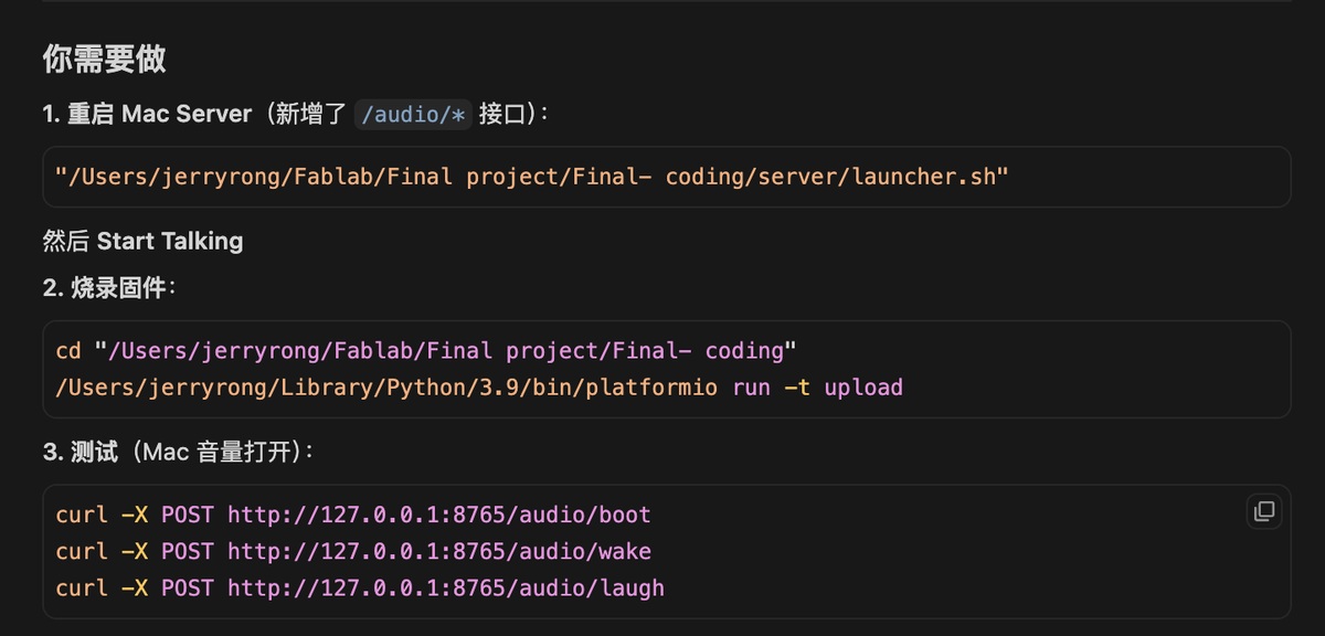
Updated Mac server
"/Users/jerryrong/Fablab/Final project/Final- coding/server/launcher.sh"
New firmware
cd "/Users/jerryrong/Fablab/Final project/Final- coding"
/Users/jerryrong/Library/Python/3.9/bin/platformio run -t upload
It runs well, as show in the video (+voice interaction/file)
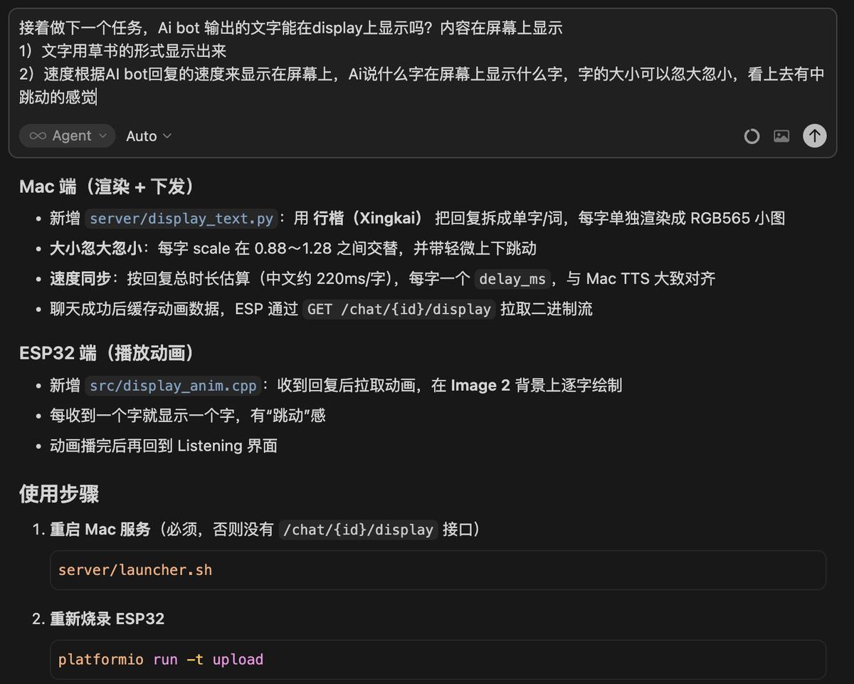
Text to the Display
My idea, Content displayed on screen:
1) Text appears in cursive script style.
2) The speed of display matches the AI bot's response speed—whenever the AI says a character, that character appears on screen, with varying sizes creating a dynamic, pulsating effect.
I use the same above as prompt (in Chinese) to Cursor, and I got a new firmware and to restart the server
Restart the server
"/Users/jerryrong/Fablab/Final project/Final- coding/server/launcher.sh"
New firmware
cd "/Users/jerryrong/Fablab/Final project/Final- coding"
pio run -t upload
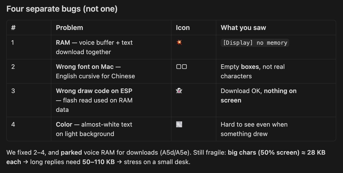
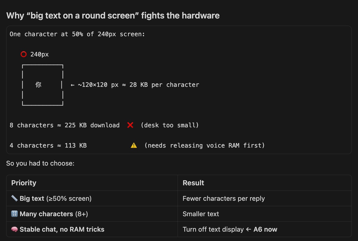
For this function, debugged in many hours, still not succeed, the Main reason is the Ram is too too small in Xiao ESP32-C3, and there is many tasks is running. Reasons analyzed by Cursor as below,
TTS
Optimize the Voice, to make it more close to a human, not a Machine I will clone the voice and apply to the TTS
There is 2 way to clone a voice, at edge or cloud, here is the comparison, F5-TTS(local) VS Cloud (ElevenLabs / Fish, etc.)
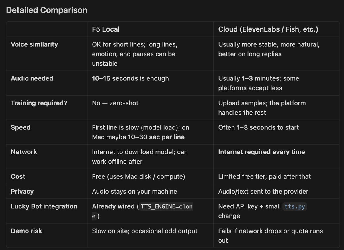
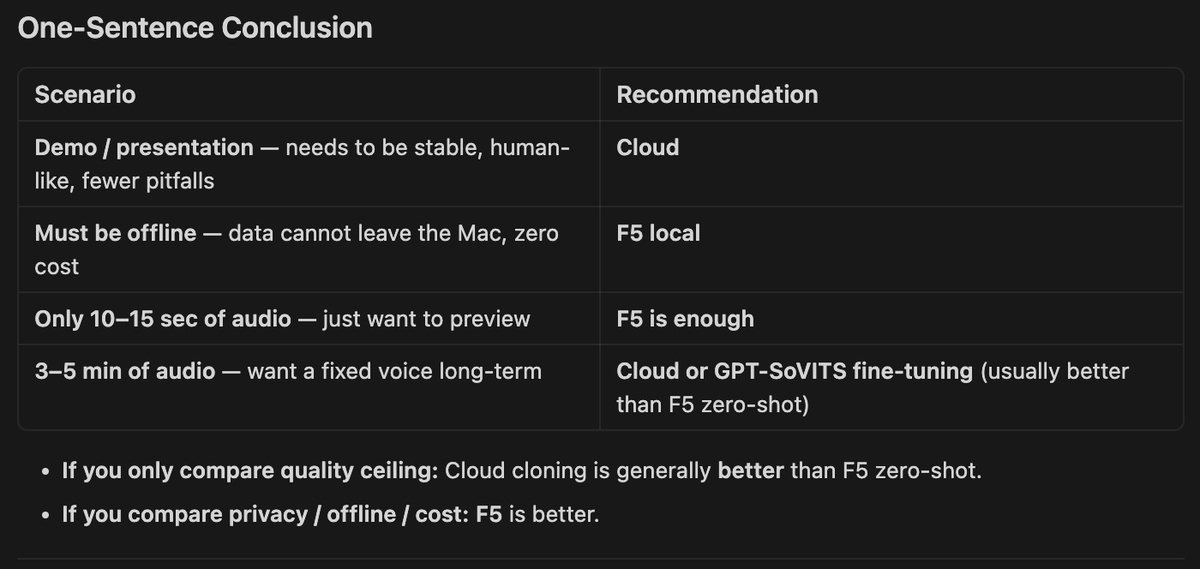
I will prefer to use the cloud for a better quality, I will run the F5 TTS first to check the voice quality first, as It is free, and already connect with my web platform
install F5-TTS, Cursor help me installed directly
Raw data of audio and Text Attach the voice sample and Text of the content

Send out the Text and Audio to Cursor, Cursor will configure automatically. With around 30 minutes, it turn out a voice, as attached, with file,clone_preview from F5 TTS
I found the speed is too fast, then I request the speed to 0.85, and keep the same quality.
Ask Cursor to configure the voice the server
But I found a big issue, F5-TTS is a local model running in my laptop, when AI bot generate the content, it need to send it to F5-TTS first, and it will takes around 5 minutes to return the audio with the designated voice.
Therefore, I need to go back to cloud again, with search, I found I will consider to use the API from iFLYTEK
Register on Iflytek you will get a month free use
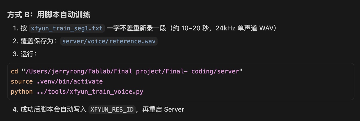
Send Cursor the documentation from Iflytek about how to train a voice model
Credentials go in server/.env (copy from .env.example) — never commit real APP ID / API keys.
After training, save the voice ID in .env:
TTS_ENGINE=xfyun
XFYUN_APP_ID=your_app_id
XFYUN_API_KEY=your_api_key
XFYUN_API_SECRET=your_api_secret
XFYUN_RES_ID=your_trained_voice_id
The audio attached. ( voice from iFlytek), Testing again, see the video
Key source code — voice interaction + TTS
Mac plays SFX cues (boot / wake ack / idle laugh) and TTS replies through the laptop speaker. ESP32 waits for playback to finish before reopening the mic (avoids echo loop).
Project files: server/tts.py, server/xfyun_tts.py, server/.env.example, include/lucky_config.h
1. TTS engine config (server/.env.example):
TTS_ENABLED=true
TTS_ENGINE=edge          # edge | macos | clone | xfyun
TTS_EDGE_VOICE=zh-CN-XiaoxiaoNeural

# iFlytek cloned voice (credentials in .env only):
# TTS_ENGINE=xfyun
# XFYUN_APP_ID=your_app_id
# XFYUN_API_KEY=your_api_key
# XFYUN_API_SECRET=your_api_secret
# XFYUN_RES_ID=your_trained_voice_id
2. Speak reply async (server/tts.py):
def tts_engine() -> str:
    """macos | edge | clone | xfyun"""
    return os.getenv("TTS_ENGINE", "edge").strip().lower()

def speak_async(text: str) -> None:
    """Queue TTS in background thread — Mac speaker, not ESP32."""
    generation = _tts_generation + 1
    threading.Thread(target=_speak_worker, args=(text, generation), daemon=True).start()

def _speak_worker(text: str, generation: int) -> None:
    engine = tts_engine()
    if engine == "xfyun":
        _speak_xfyun(text, generation)
    elif engine == "edge":
        _speak_edge(text, generation)
    # ... macos / F5 clone fallback ...
3. ESP32 waits for Mac playback (include/lucky_config.h):
constexpr uint32_t kWakeSfxDurationMs = 3200;    // wake ack SFX ~3 s
constexpr uint32_t kSessionVadIgnorePadMs = 1800; // ignore mic during TTS echo
constexpr uint32_t kPlaybackWaitMaxMs = 35000;    // wait for Mac TTS done
4. Session loop — mute mic during bot speech (src/main.cpp):
// After /chat returns tts_ms + playback_epoch:
waitForPlaybackDone(host, port, chat.playbackEpoch, chat.ttsMs);
wakeRestoreMic();                    // reopen mic only after Mac finishes
if (sessionUserSpoke()) {
  recordAndUpload(host, port);       // user's next utterance
}
Expected behaviour: Lucky replies on Mac speaker → ESP32 keeps mic closed until playback ends → user can speak again without the bot hearing its own voice.
Optimize on the voice interaction.
Timing
Gap between human voice and Ai
Gap between Ai and human voice
Sensitivity of the wake up word
Current status: hard to wake up Lucky Bot, I need call him 4-5 times more, the reason is the whisper I used, I will use another whisper model for the key words wake up. The reason analyze from Cursor
I downloaded the new Whisper Tiny model and deployed it on the Mac. There is a big improvement — it works normally with just 1–2 calls when the sound is clear.
Quality of the content, better to use a cloud API
31st, May — the best firmware version so far:
cd "/Users/jerryrong/Fablab/Final project/Final- coding"
/Users/jerryrong/Library/Python/3.9/bin/platformio run -t upload
How to recovery the current firmware version. Just in case :
Approach 1. burn the firmware below,
cd "/Users/jerryrong/Fablab/Final project/Final- coding"
./tools/restore_firmware.sh A6n
Approach 2, burn from the source code
unzip -o firmware_backups/A6n-source-20260531.zip -d .
/Users/jerryrong/Library/Python/3.9/bin/platformio run -t upload
Change to OpenAI API instead of the Ollama running Qwen
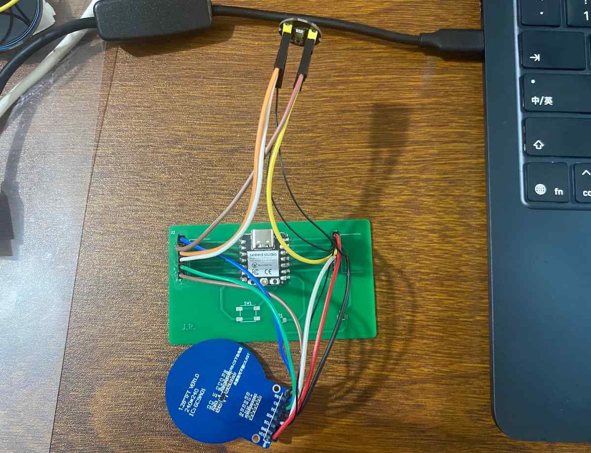
Assemble from breadboard to PCB
I used the PCB made in Assignment 6, and assemble them together with the same wiring. As below

Burn the firmware to another Xiao ESP C3
Connect with Cursor
Check/find the port
Burn the firmware
cd "/Users/jerryrong/Fablab/Final project/Final- coding"
./tools/restore_firmware.sh A6n /dev/cu.usbmodemXXX
XXX means the port in the new board
Assemble the Lucky Bot
The 3 major parts as below,
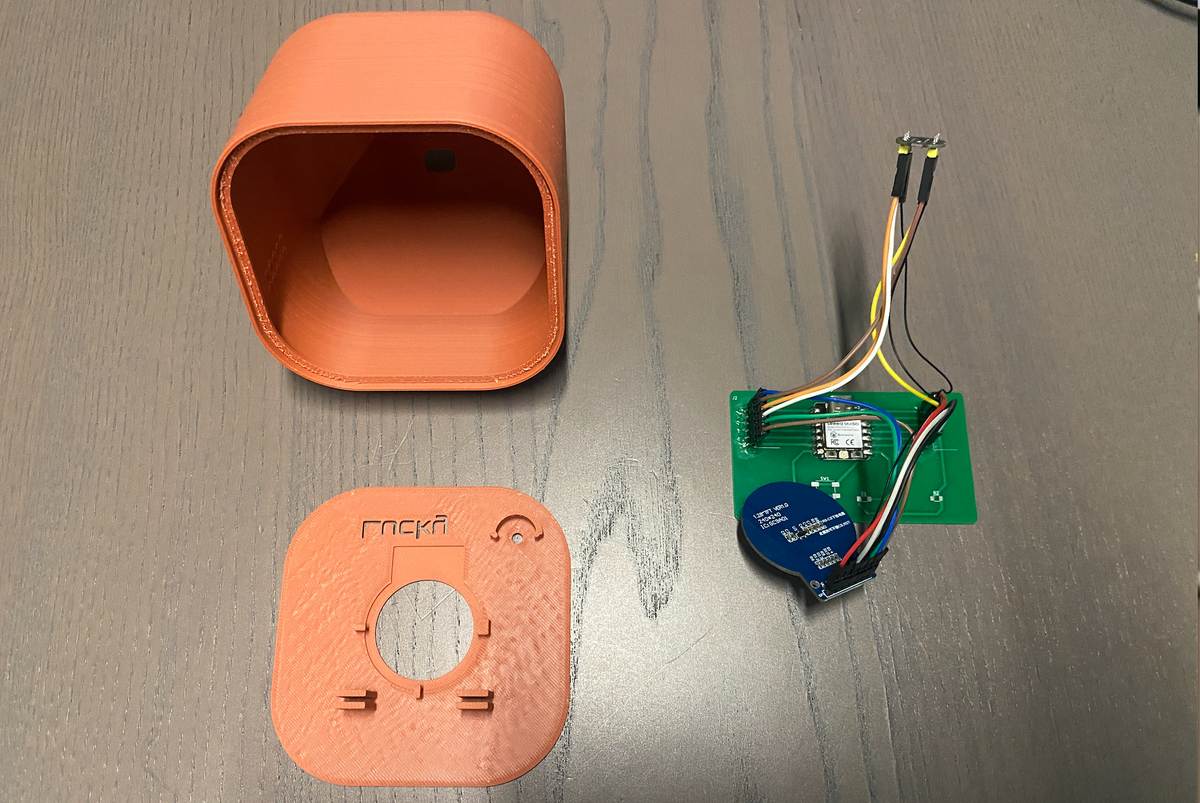
Add the PCB, display and mic to the related position with some structure to fix them
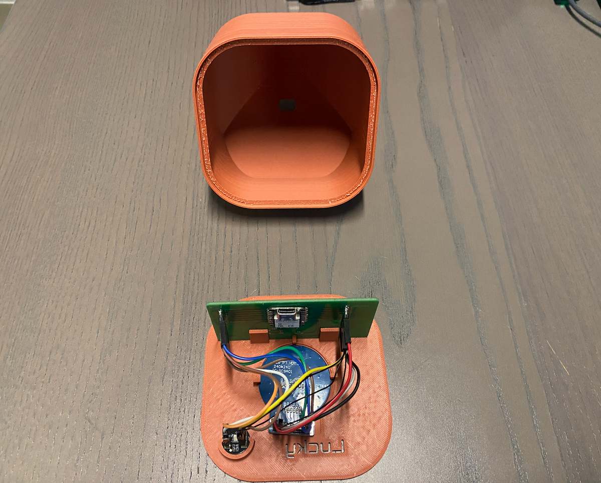
insert the top cover to the enclosure part,
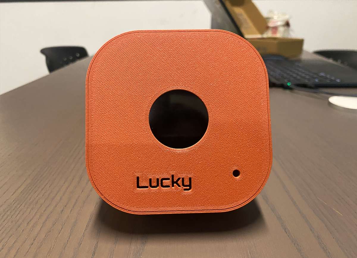
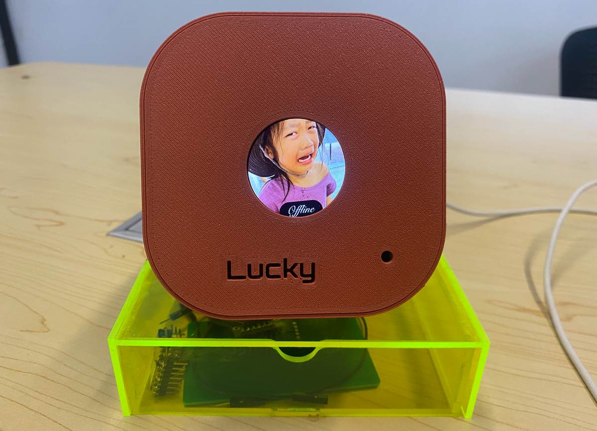
Connect with USB cable and test again. I feel it is good — the best condition so far, as the video below:
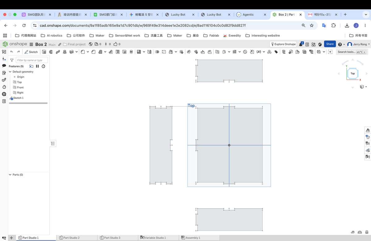
2D
My idea is to make a small stand for the Lucky Bot, Lucky Bot is desktop device, so I will place the bot on the stand, and meanwhile the bot could be regard as a small storage box on my desk.
I draw the sketch, as below,
Use onshape to make the design file, . Onshape link for reference
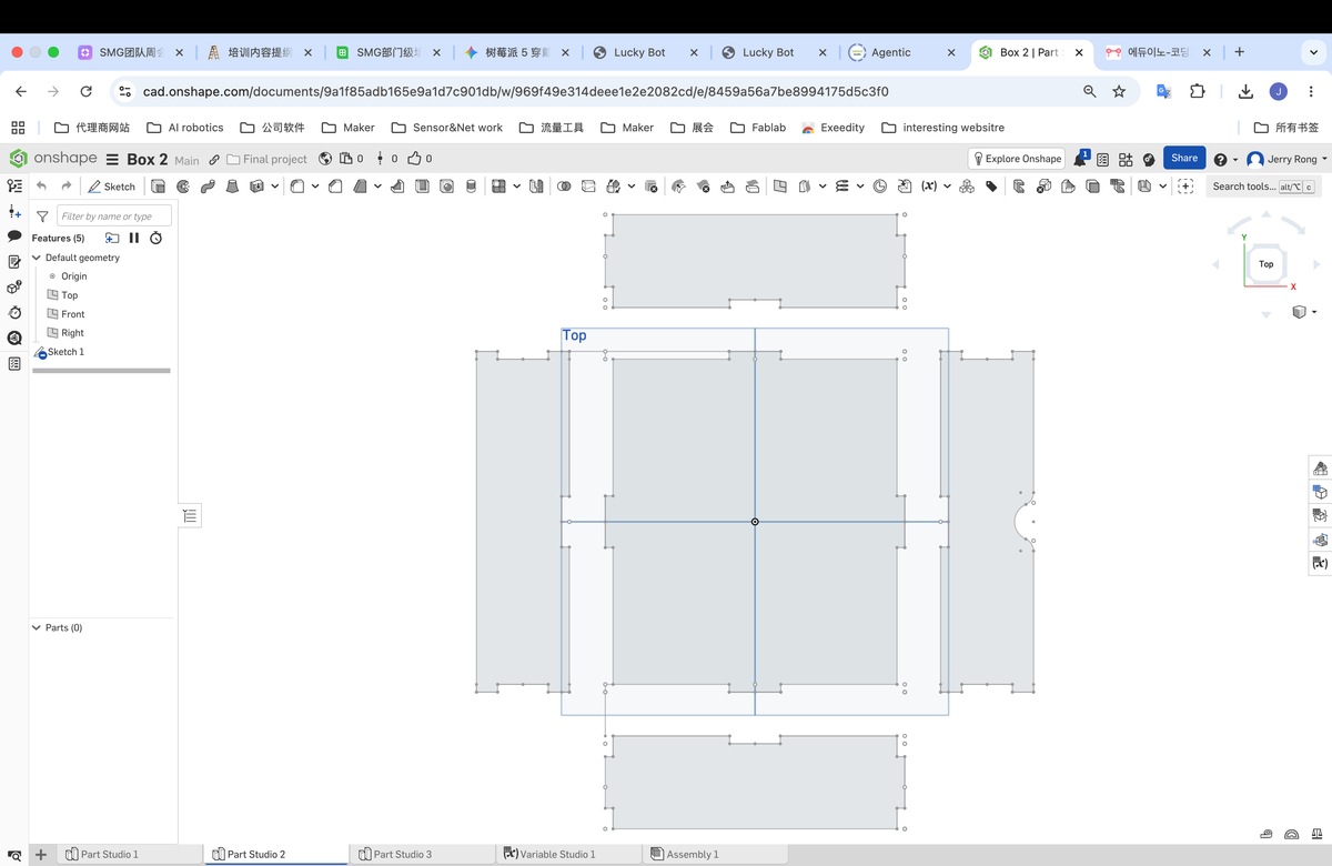
A testing file to confirm the kerf, When the Male part is 20mm, the female part will be 19.6 mm, the match is the best.
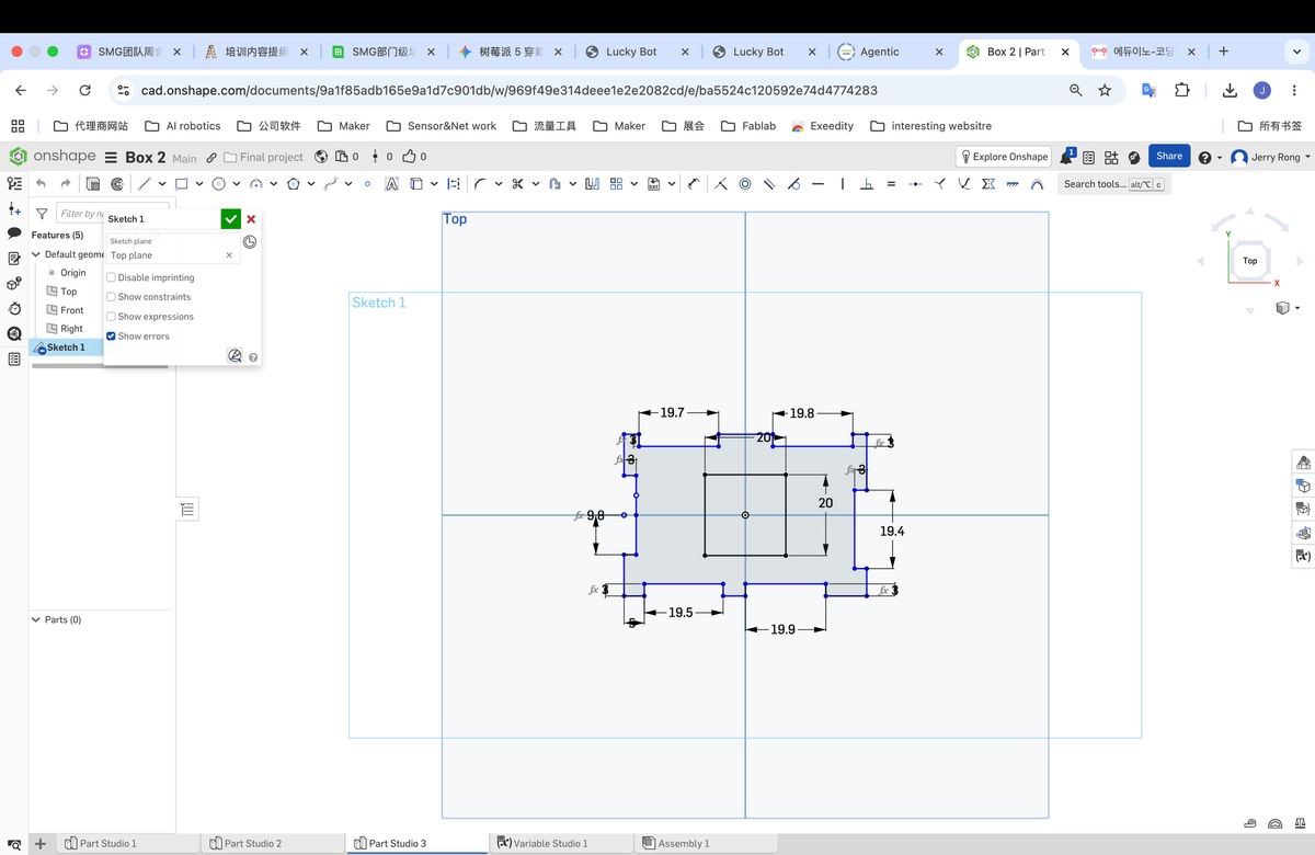
I export the file with DXF, and use laser maker to combine them together,
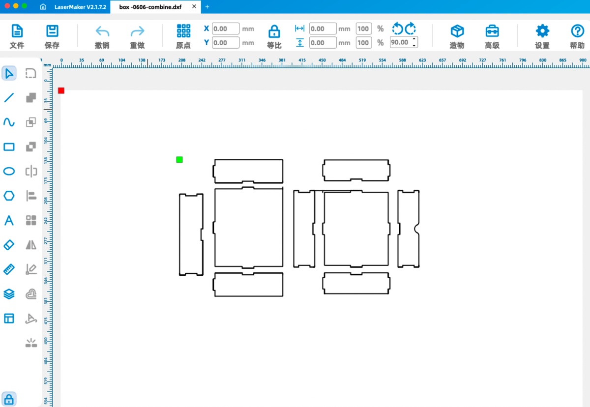
Combined dxf file as attached.
I use the Laser cutter to make the stand/ box,and assemble them.
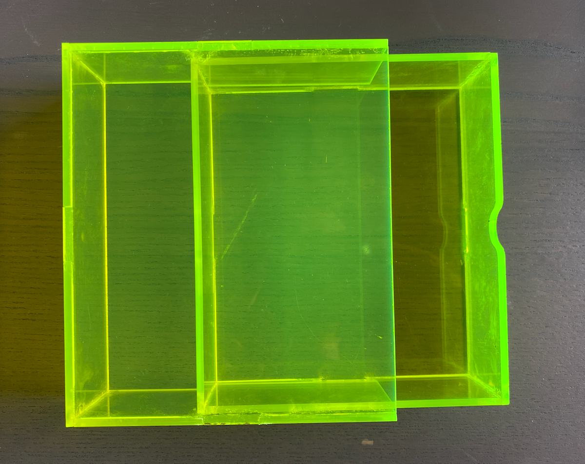
The finished final project
Presentation:
1)Slide:
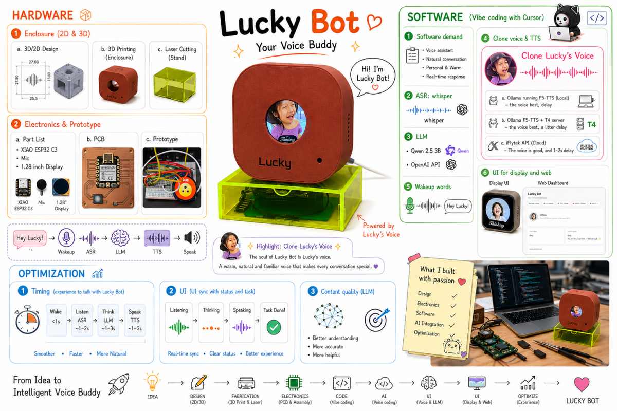
2)Video: