Week 4 Embedded Programming
Group Assignment
Test and compare different development software and programming languages, like Arduino, Micropython,ESP-IDF,or more
Individual Assignment
Choose an MCU board as the hardware programming platform
check the datasheet of the chip used in the MCU and record, architechture,Memory,Peripherals(ADC,etc),supported programming software,or more
Use simulation software to program the selected board. Create three programs:
2.1 Basic operation (e.g., turn on the LED on the board)
2.2 Connect an input or output device and successfully read/display data
2.3 Use the communication methods supported by the board (Wired: UART, I2C, SPI;Wireless: Wi-Fi, Bluetooth)
Individual Assignment
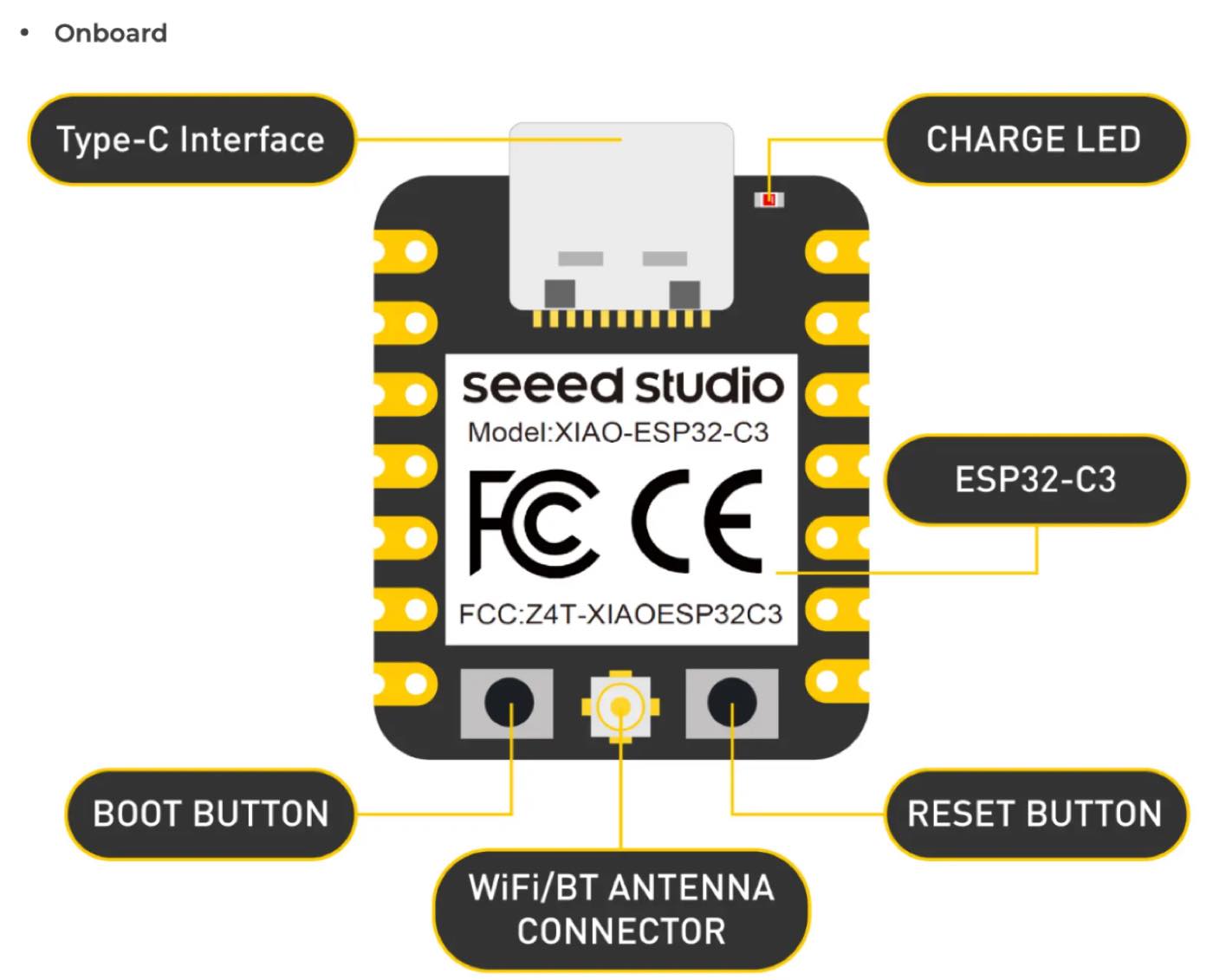
XIAO ESP32-C3
Seeed Studio XIAO ESP32-C3 adopts new RISC-V architecture, supporting both Wi-Fi and BLE wireless connectivities, widely used for IoT project.
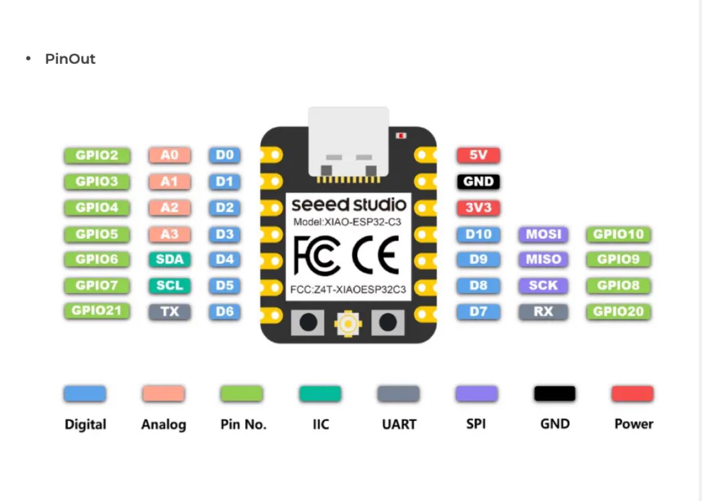
| Color | Label | Functional Description |
| Pink | Touch | Capacitive Touch pins. These can detect electrical charges from a human finger, allowing you to create touch-sensitive buttons without mechanical parts. |
| Green | Digital | Digital Input/Output (I/O) pins. These pins handle binary signals: either High (3.3V) or Low (0V). |
| Orange | Analog | Analog-to-Digital Converter (ADC) pins. These can measure varying voltage levels (e.g., from a potentiometer or light sensor) and convert them into digital values. |
| Grey | GPIO | General Purpose Input/Output. This is the standard label for pins that can be programmed to perform various input or output tasks. |
| Dark Grey | IIC (I2C) | Stands for Inter-Integrated Circuit. A communication protocol using two wires (SDA for data and SCL for clock) to connect sensors, OLED screens, and other modules. |
| Red | Power | Power pins. Includes 5V (USB power/External input) and 3V3 (regulated 3.3V output for the chip and low-power peripherals). |
| Black | GND | Ground. The common reference point (0V) for the entire electrical circuit. Always connect your oscilloscope ground clip here. |
| Yellow | SPI | Serial Peripheral Interface. A high-speed synchronous data bus used for fast communication with devices like SD card modules or LCD displays. |
| Blue | UART | Universal Asynchronous Receiver/Transmitter. Used for serial communication (TX/RX), typically for debugging or communicating with a computer or GPS modules. |
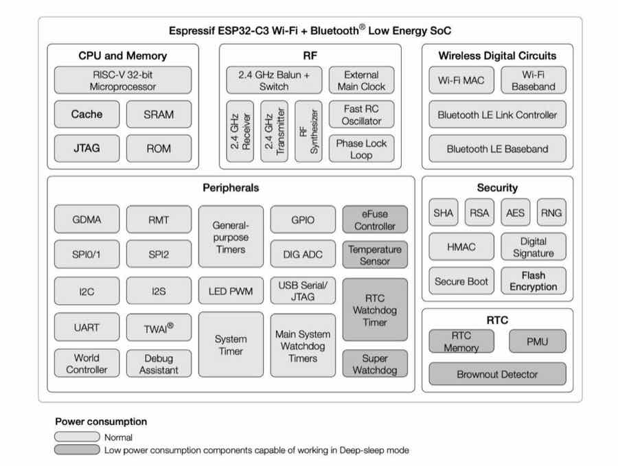
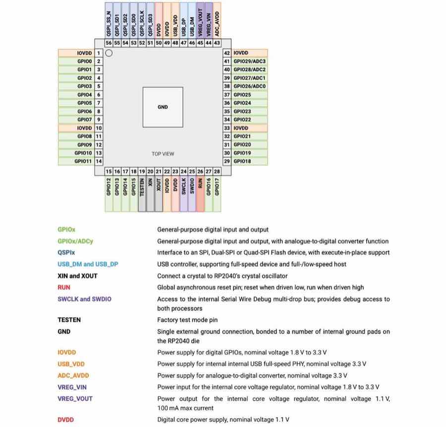
Feature of the SOC
ESP32-C3 is a low-power and highly-integrated MCU-based solution that supports 2.4 GHz Wi-Fi and Bluetooth® Low Energy (Bluetooth LE). The functional block diagram of the SoC is shown below.
Programming software
Arduino IDE
MicroPython / CircuitPython
VS Code + PlatformIO
ESP-IDF
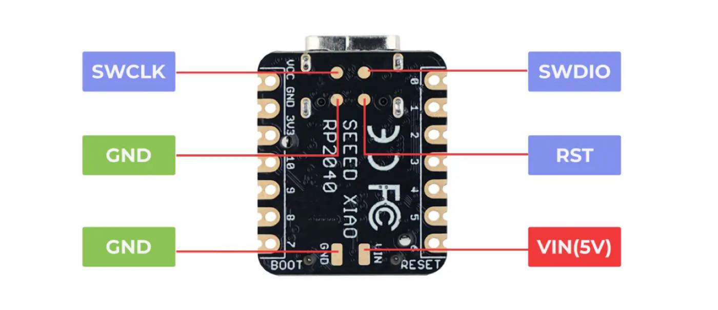
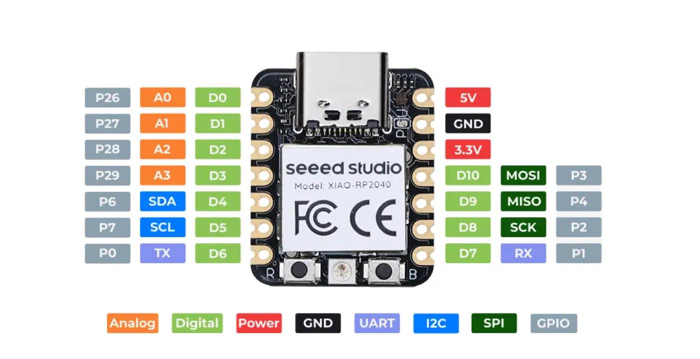
XIAO RP2040
XIAO RP2040 is a compact, Arduino-compatible dev board based on Raspberry Pi RP2040,a cost-effective and user-friendly microcontroller for learning coding. (without Wireless connectivity)
Feature of the SoC
Programming software
Arduino IDE
Python
VS Code + PlatformIO
Microsoft MakeCode
C/C++ SDK (CMake)
Seeed Xiao ESP32 C3 VS Seeed Xiao RP2040 - Main difference
| Description | Xiao ESP 32-C3 | Xiao RP2040 |
| Architecture | RISC-V | Dual-core ARM Cortex-M0+ |
| Processor | ESP 32 -C3 | Rasperry pi 2040 |
| Wireless connectivity | Wifi,BLE | no |
| Power | Support 3.7 v Li-ion(battery) | no |
| Application | Iot project for scaling up | IoT prototying/Learning |
Coding Environment
Xiao ESP 32 C3 with Arduino IDE
Xiao ESP 32 C3 with Microphython
Xiao ESP 32 C3 with CircuitPython
Running on simulation software (https://wokwi.com/)
Turn on the LED
Step 1 open the website and select Xiao ESP32-S3
Step 2 select the module, LED and resistor, a resistor is required for the circuit.
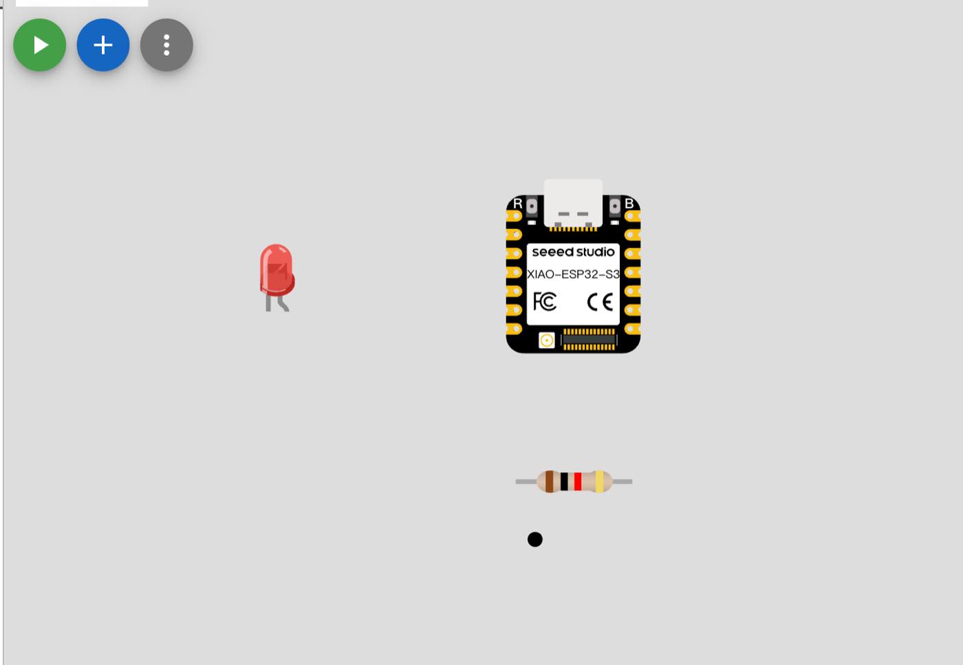
Step 3 connect them to a circuit
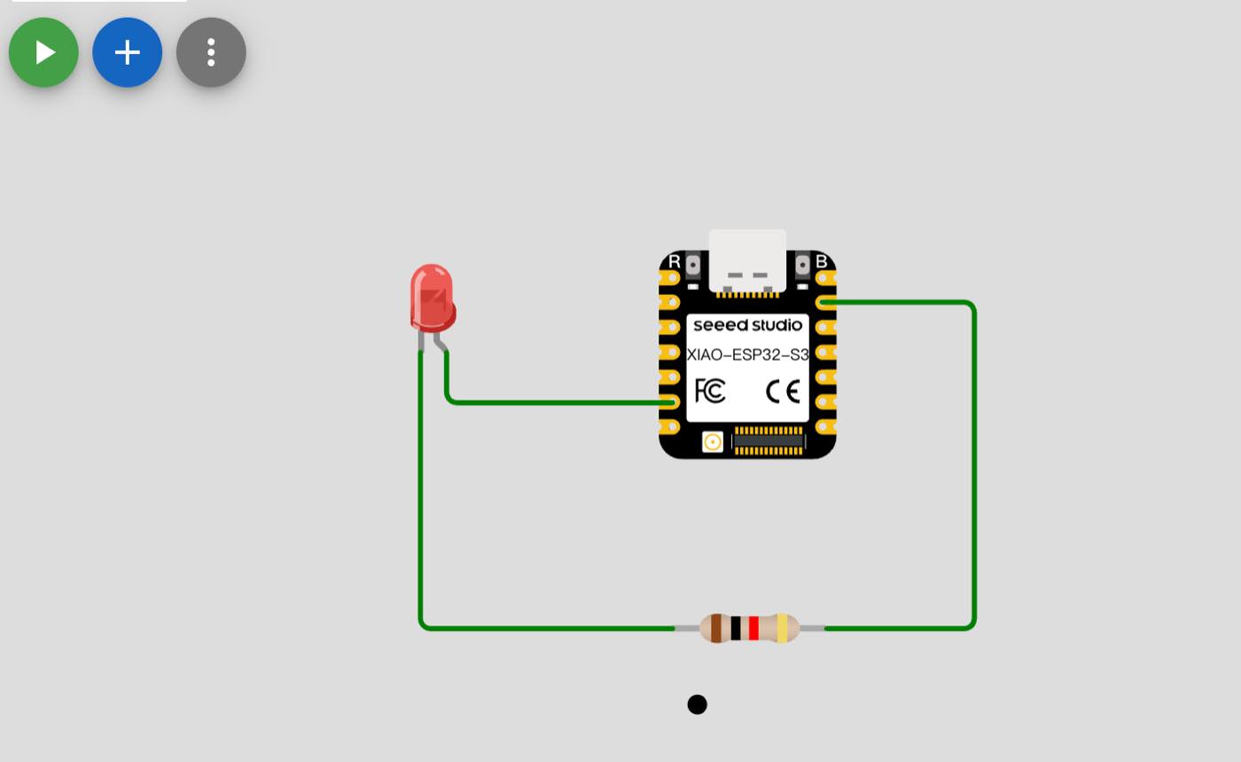
Step 4 turn on the LED, 1s on and 1s off and loop
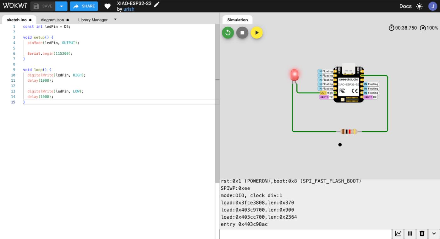
The Code was generated by Gemini
// Basic LED blink on XIAO ESP32C3
void setup() {
  // Configure D5 as output pin
  pinMode(D5, OUTPUT);
}

void loop() {
  // LED ON for 1 second
  digitalWrite(D5, HIGH);
  delay(1000);

  // LED OFF for 1 second
  digitalWrite(D5, LOW);
  delay(1000);
}
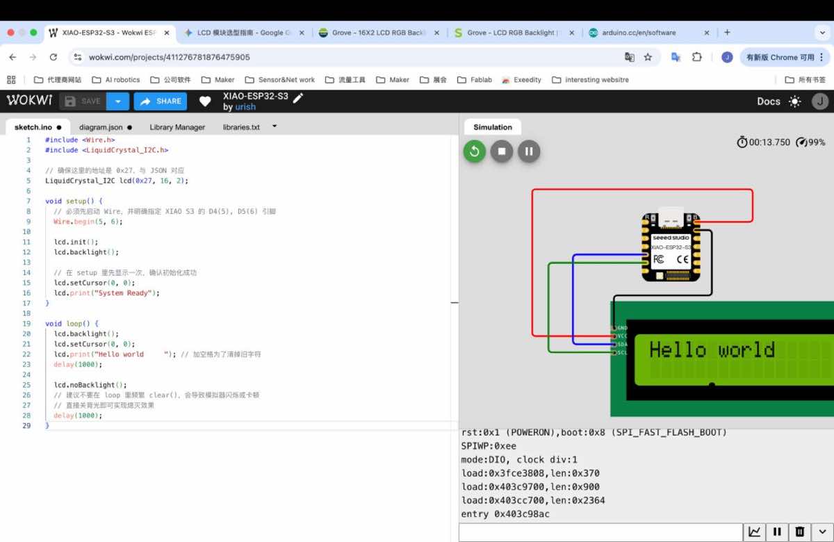
“Hello World”
When connected with power, it will show “ hello Word” for 1 second, and stop 1 second, and the repeated.
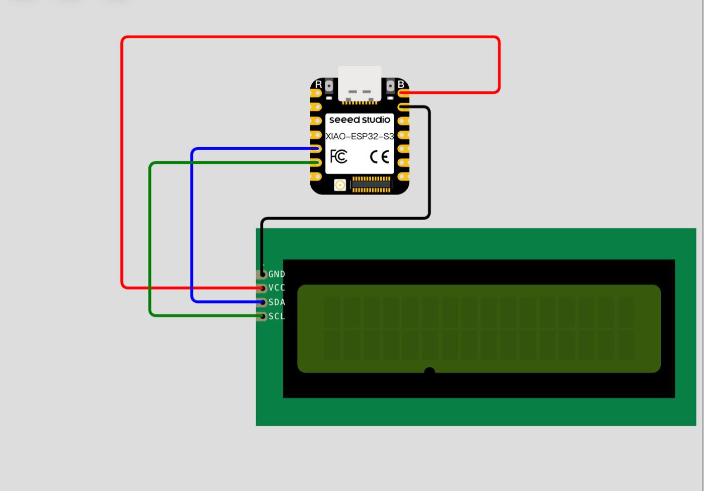
Step 1 select the 2 module, Xiao -ESP 32 -S3 and LCD 16x2 (I2C)
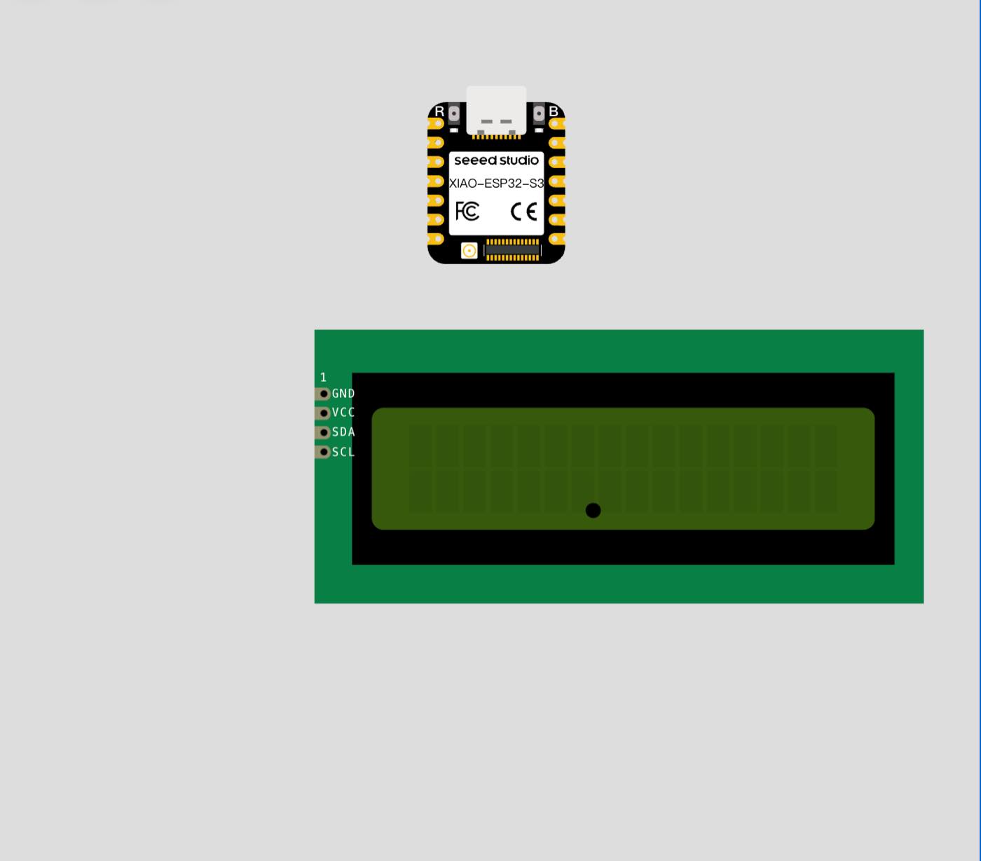
Pin of LCD 16x2 (I2C)
| Pin Name | Full Name | Description | Connection (XIAO S3) |
| GND | Ground | The common reference point for the electrical circuit (Negative pole). It must be connected to complete the circuit. | GND |
| VCC | Voltage Collector Common | The power supply input for the LCD and the I2C adapter. Most LCDs require 5V for optimal contrast. | 5V / VIN |
| SDA | Serial Data | The bidirectional line used to transmit data bits between the ESP32-S3 and the LCD display. | D4 (GPIO 5) |
| SCL | Serial Clock | The signal line that carries the clock pulses to synchronize the data transfer on the SDA line. | D5 (GPIO 6) |
Step 2 connect with cable as below
Step 3 code as below
#include <Wire.h>
#include <LiquidCrystal_I2C.h>

// Make sure I2C address matches your module/JSON config
LiquidCrystal_I2C lcd(0x27, 16, 2);

void setup() {
  // Start I2C with XIAO S3 pin mapping: SDA=D4(GPIO5), SCL=D5(GPIO6)
  Wire.begin(5, 6);

  // Initialize LCD and turn on backlight
  lcd.init();
  lcd.backlight();

  // Show startup message once
  lcd.setCursor(0, 0);
  lcd.print("System Ready");
}

void loop() {
  // Display text with backlight on
  lcd.backlight();
  lcd.setCursor(0, 0);
  lcd.print("Hello world "); // trailing space clears leftover characters
  delay(1000);

  // Turn off backlight for 1 second
  lcd.noBacklight();

  // Avoid frequent clear() in loop to reduce flicker
  delay(1000);
}
Finally, it works as below,
Light up the LED in the physical world
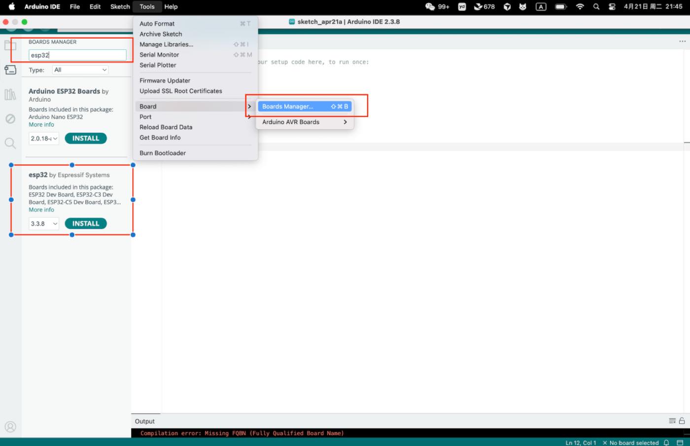
Step 1 download the Arduino IDE, add ESP32 board package to your Arduino IDE
Navigate to File > Preferences, and fill "Additional Boards Manager URLs" with the url below: https://jihulab.com/esp-mirror/espressif/arduino-esp32.git
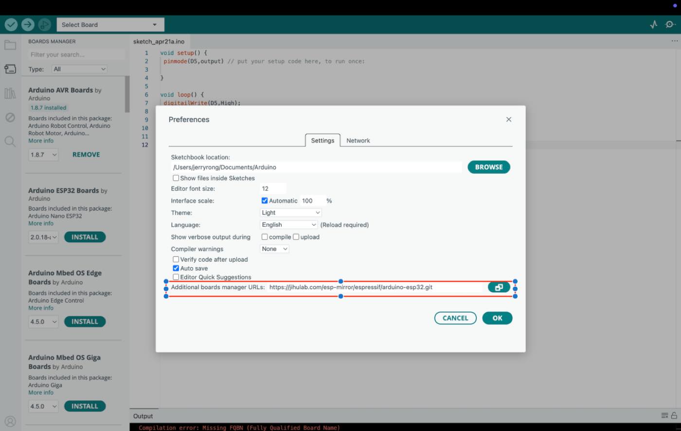
Install the ESP32 board package
Step2 Make a circuit as below, with Xiao ESP32 C3, cable, and LED, bread board.
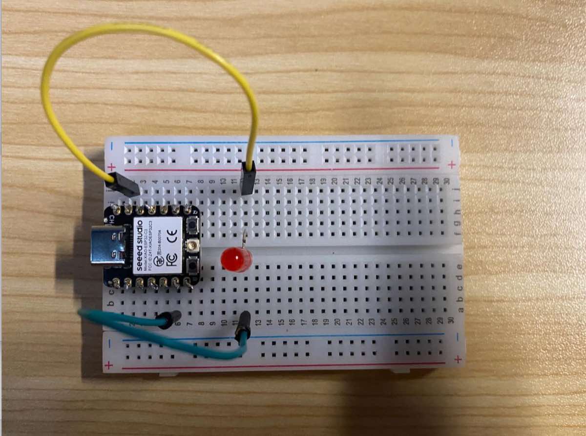
Step 3 Copy the Code as above and run the program to light up the LED as in the video.