Week 9 Input Devices
Group assignment
Week 9 Chaihuo group assignment.
Individual assignment
Based on my final project, I am trying to build a prototype to connect the human voice for a voice interaction device. The input part will be the mic. The materials I will use are:
Components
-
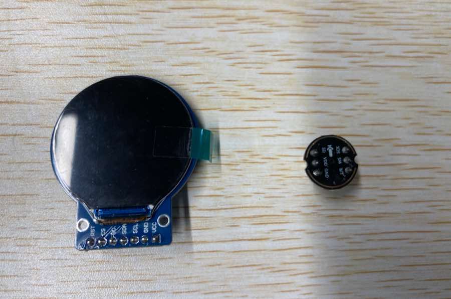
Input: microphone, INMP441, as picture below
-
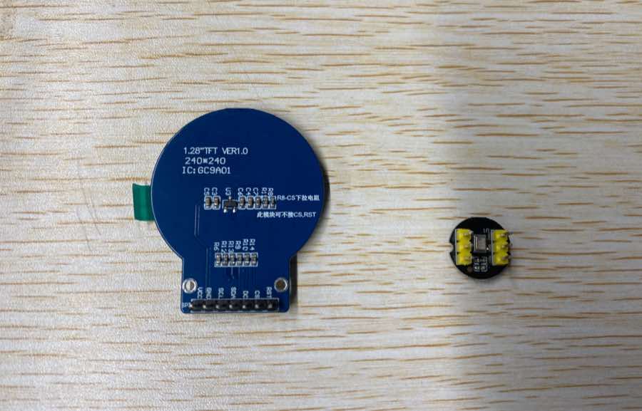
Output: display, GC9A01 1.28 inch, LCD, SPI display, as picture below
-
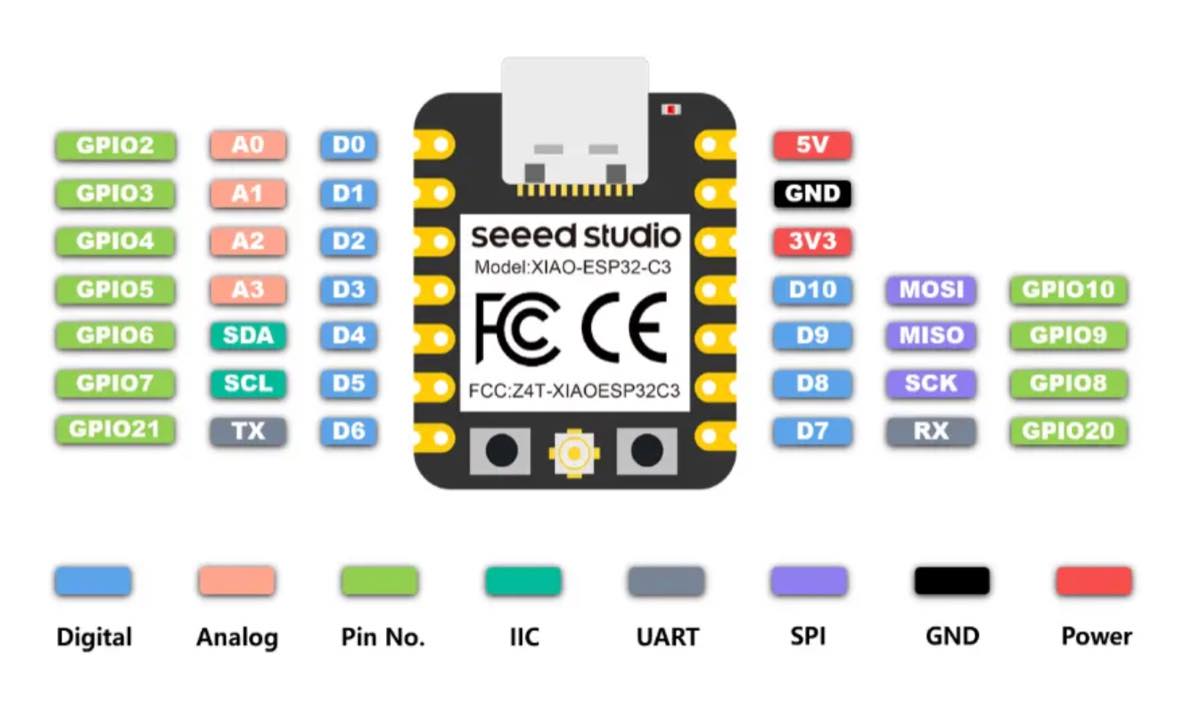
MCU: Xiao ESP32-C3
-
Breadboard
-
Cables
Learning the pins of each component and wiring
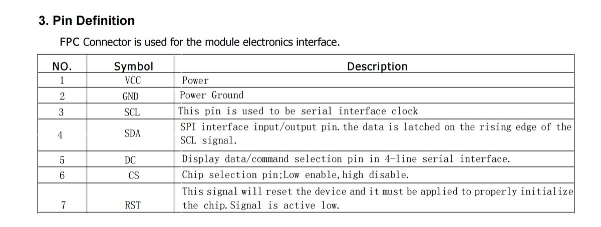
Pin of display
Pin of the microphone
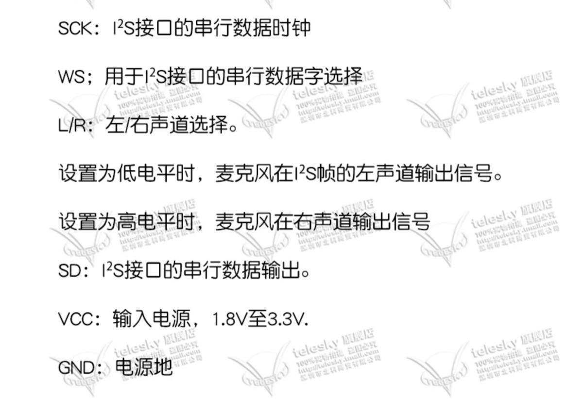
Microphone pin descriptions (English)
-
SCK: Serial data clock for the I²S interface.
-
WS: Serial data word select for the I²S interface.
-
L/R: Left/Right channel selection.
-
When set to Low level (GND), the microphone outputs signals on the left channel of the I²S frame.
-
When set to High level (VCC), the microphone outputs signals on the right channel of the I²S frame.
-
SD: Serial data output for the I²S interface.
-
VCC: Power input, 1.8V to 3.3V
-
GND: Power ground.
Wiring
ESP32-C3 I/O overview
Microphone (INMP441) ➔ Seeed XIAO ESP32-C3 Wiring
Standard I2S digital audio bus connection:
| Microphone Pin (INMP441) | Seeed XIAO ESP32-C3 Physical Pin | Corresponding Pin in Code (GPIO) | Bus Function Description |
|---|---|---|---|
| VCC | 3.3V | 3.3V | Digital power supply for the microphone. |
| GND | GND | GND | Power ground. |
| L/R | GND | GND | Grounded (Low): Outputs Left Channel for single-channel (Mono) audio. |
| SCK | D2 | GPIO 4 | I2S Serial Bit Clock line (BCLK). |
| WS | D3 | GPIO 5 | I2S Word Select / Frame Clock line (LRCK). |
| SD | D1 | GPIO 3 | I2S Serial Data Out line (audio data input to the MCU). |
Round screen (GMT128-02 / GC9A01) ➔ Seeed XIAO ESP32-C3 Wiring
4-line SPI serial bus connection:
| Screen Pin (GMT128-02) | Seeed XIAO ESP32-C3 Physical Pin | Corresponding Pin in Code (GPIO) | Adjustment & Advantage Description |
|---|---|---|---|
| 1. VCC | 5V | 5V | Connects to the stable 5V rail to ensure enough power for the backlight. |
| 2. GND | GND | GND | Power ground (must share a common ground with the microphone). |
| 3. SCL | D8 | GPIO 8 | Hardware Fixed: SPI Serial Clock line (SCK). |
| 4. SDA | D10 | GPIO 10 | Hardware Fixed: SPI Serial Data Out line (MOSI). |
| 5. DC | D4 | GPIO 6 | Data/Command selection pin. |
| 6. CS | D0 | GPIO 2 | Strapping Pin Warning: Please check the crucial boot note below. |
| 7. RST | D5 | GPIO 7 | Hardware reset pin (active low). |
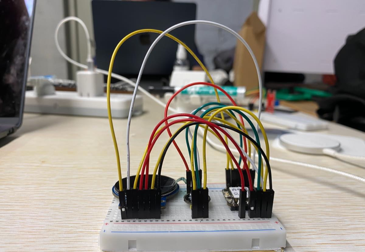
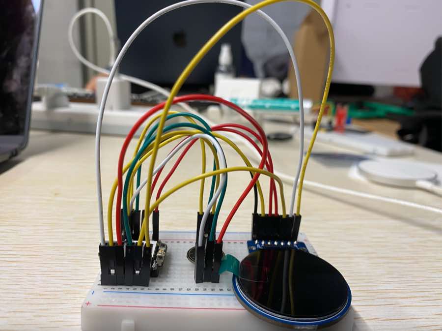
With a breadboard and cables
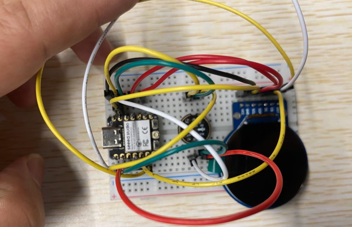
Debug and test mic
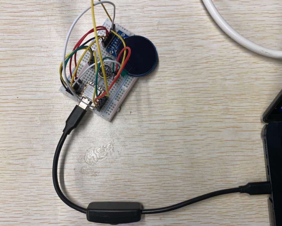
Step 1 Connect the prototype with laptop
Step 2 Use Cursor to debug
-
Ask Cursor to check the connection
-
Tell Cursor the demand: Xiao ESP32-C3 + display (GC9A01) + mic (INMP441)
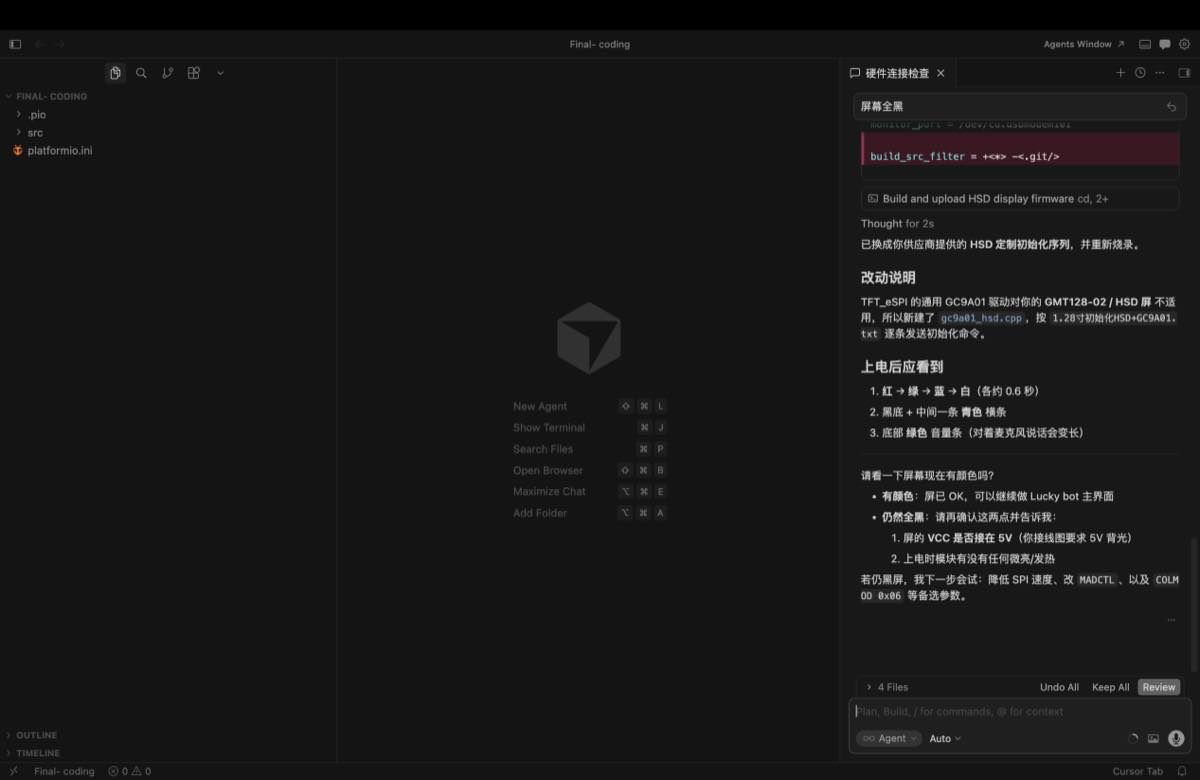
Cursor checks the pin connection. I sent the settings above as pictures.
Debug on the connection, setting as below from Cursor
Upon powering up, you should observe the following:
-
Red → Green → Blue → White (approx. 0.6 seconds each)
-
Black background with a cyan horizontal bar in the center
-
A green volume bar at the bottom (elongates when speaking into the microphone); it shows the mic works well, see the video
Key source code — hardware debug (May 16)
Early prototype test firmware for Xiao ESP32-C3 + GC9A01 round LCD + INMP441 mic.
The standalone debug sketch was later merged into the full Lucky Bot firmware; the pin map and drivers below are from the current project and match this breadboard test.
1. Pin map (src/gc9a01_hsd.h, src/mic_i2s.cpp):
// GC9A01 round LCD (SPI)
constexpr int PIN_LCD_CS   = 2;   // D0
constexpr int PIN_LCD_DC   = 6;   // D4
constexpr int PIN_LCD_RST  = 7;   // D5
constexpr int PIN_LCD_SCK  = 8;   // D8
constexpr int PIN_LCD_MOSI = 10;  // D10

// INMP441 microphone (I2S)
constexpr gpio_num_t I2S_PIN_BCLK = GPIO_NUM_4;  // D2
constexpr gpio_num_t I2S_PIN_WS   = GPIO_NUM_5;  // D3
constexpr gpio_num_t I2S_PIN_DIN  = GPIO_NUM_3;  // D1
2. LCD init — vendor HSD sequence (src/gc9a01_hsd.cpp):
bool GC9A01_HSD::begin() {
  pinMode(PIN_LCD_CS, OUTPUT);
  pinMode(PIN_LCD_DC, OUTPUT);
  pinMode(PIN_LCD_RST, OUTPUT);

  digitalWrite(PIN_LCD_RST, LOW);
  delay(20);
  digitalWrite(PIN_LCD_RST, HIGH);
  delay(120);

  spi_.begin(PIN_LCD_SCK, -1, PIN_LCD_MOSI, -1);
  spi_.beginTransaction(SPISettings(27000000, MSBFIRST, SPI_MODE0));

  runHsdInit();   // GC9A01 vendor init from 1.28" HSD datasheet
  Serial.println("[LCD] HSD GC9A01 init done");
  return true;
}
3. Microphone init (src/mic_i2s.cpp):
bool micBegin() {
  i2s_config_t cfg = {};
  cfg.mode = (i2s_mode_t)(I2S_MODE_MASTER | I2S_MODE_RX);
  cfg.sample_rate = 16000;
  cfg.bits_per_sample = I2S_BITS_PER_SAMPLE_32BIT;
  cfg.channel_format = I2S_CHANNEL_FMT_ONLY_LEFT;

  i2s_pin_config_t pins = {};
  pins.bck_io_num = I2S_PIN_BCLK;
  pins.ws_io_num = I2S_PIN_WS;
  pins.data_in_num = I2S_PIN_DIN;

  i2s_driver_install(I2S_NUM_0, &cfg, 0, nullptr);
  i2s_set_pin(I2S_NUM_0, &pins);
  return true;
}
4. Boot test — colour flash + live mic level bar (early debug main.cpp logic):
#include "gc9a01_hsd.h"
#include "mic_i2s.h"

GC9A01_HSD lcd;

void bootColorTest() {
  const uint16_t colors[] = {COLOR_RED, COLOR_GREEN, COLOR_BLUE, COLOR_WHITE};
  for (uint16_t c : colors) {
    lcd.fillScreen(c);
    delay(600);   // ~0.6 s each — confirms SPI + display wiring
  }
}

void drawMicLevel(int32_t rms) {
  lcd.fillScreen(COLOR_BLACK);
  lcd.fillRect(0, 110, 240, 20, COLOR_CYAN);              // centre bar
  const int w = constrain(map(rms, 0, 2500, 0, 240), 0, 240);
  lcd.fillRect(0, 220, w, 16, COLOR_GREEN);             // volume bar
}

void setup() {
  Serial.begin(115200);
  lcd.begin();
  bootColorTest();
  micBegin();
}

void loop() {
  int16_t samples[320];
  const size_t n = micReadSamples(samples, 320, 50);
  int64_t sum = 0;
  for (size_t i = 0; i < n; i++) sum += (int64_t)samples[i] * samples[i];
  const int32_t rms = n ? (int32_t)sqrt((double)sum / n) : 0;
  drawMicLevel(rms);
  delay(50);
}
Expected result on screen: Red → Green → Blue → White, then black screen with cyan centre bar and a green bottom bar that grows when speaking into the mic.
Update on 27th, Jun.
Use my own board for the input testing. Per my previous assignment, I made a demo and tested it on a breadboard. As below, the INMP441 microphone has been connected with the PCB together by cable.
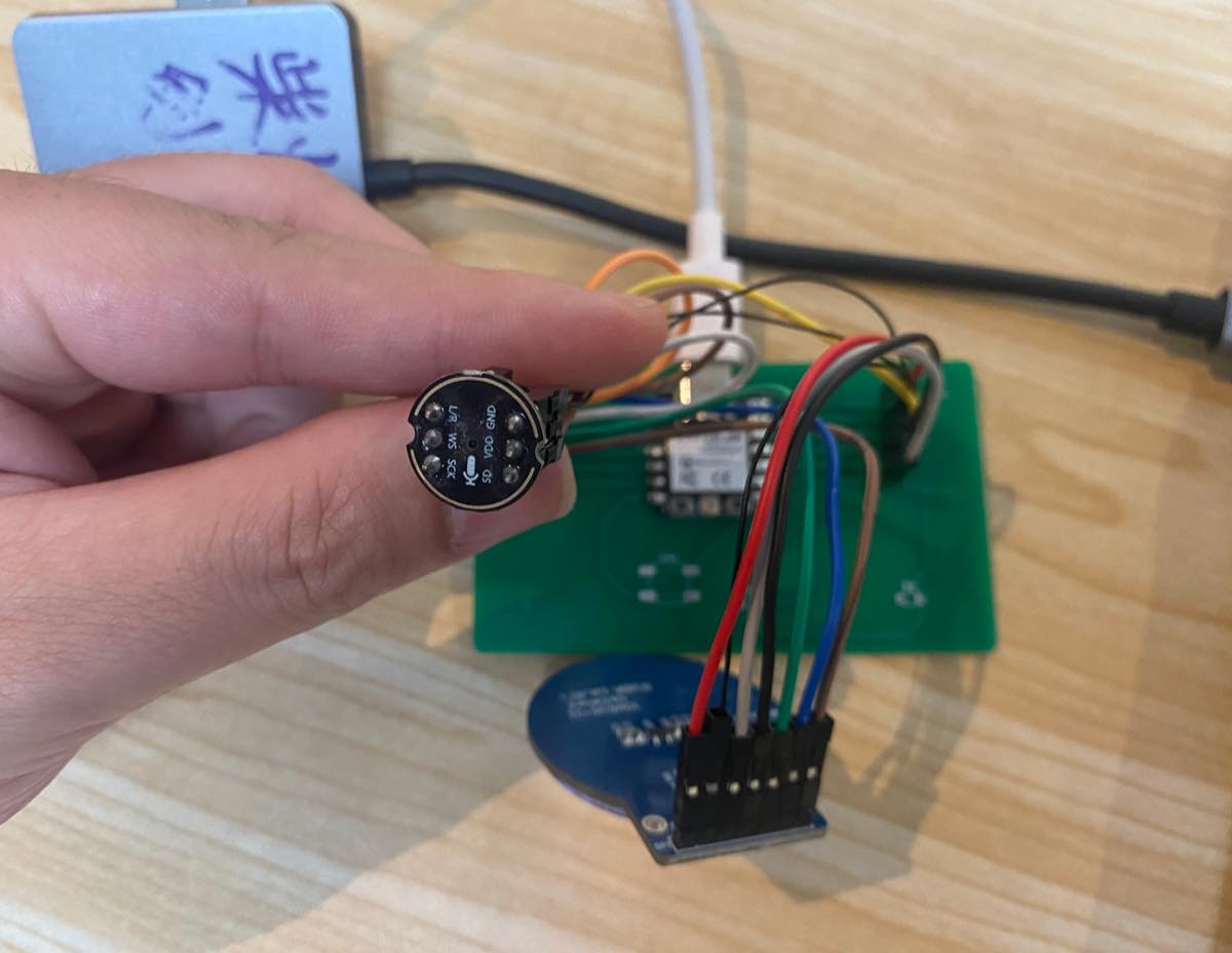
Connect with my laptop, with the same Wi-Fi setting. INMP441 microphone as the input of the whole system, I say "Lucky" to wake up, and the voice has been captured by the INMP441 microphone and uploaded to the cloud. It takes a few seconds to respond and get the reply from the cloud. As the video below,
Key source code — microphone recording (INMP441 @ 16 kHz)
Firmware on Seeed Xiao ESP32-C3 + INMP441 reads audio over I2S, records PCM until silence (VAD), wraps a WAV file, and uploads to the Mac ASR server.
Project files: Final- coding/src/mic_i2s.cpp, wav_util.cpp, main.cpp, asr_client.cpp
1. Audio config (include/lucky_config.h):
constexpr uint32_t kMicSampleRate = 16000;      // 16 kHz mono
constexpr uint32_t kMaxRecordSeconds = 4;       // max buffer after WiFi up
constexpr uint32_t kSilenceStopMs = 800;        // pause this long → stop recording
constexpr uint32_t kMinSpeechMs = 500;          // ignore clicks shorter than this
constexpr int32_t kSpeechRmsThreshold = 420;    // RMS threshold — lower = more sensitive
constexpr uint32_t kMaxWaitSpeechMs = 12000;    // wait for user to start speaking
2. Pin map + I2S init (src/mic_i2s.cpp):
// INMP441 — per wiring diagram
constexpr gpio_num_t I2S_PIN_BCLK = GPIO_NUM_4;  // D2
constexpr gpio_num_t I2S_PIN_WS   = GPIO_NUM_5;  // D3
constexpr gpio_num_t I2S_PIN_DIN  = GPIO_NUM_3;  // D1

bool micBegin() {
  i2s_config_t cfg = {};
  cfg.mode = (i2s_mode_t)(I2S_MODE_MASTER | I2S_MODE_RX);
  cfg.sample_rate = kMicSampleRate;
  cfg.bits_per_sample = I2S_BITS_PER_SAMPLE_32BIT;
  cfg.channel_format = I2S_CHANNEL_FMT_ONLY_LEFT;
  cfg.communication_format = (i2s_comm_format_t)(I2S_COMM_FORMAT_I2S);
  cfg.dma_buf_count = 4;
  cfg.dma_buf_len = 256;

  i2s_pin_config_t pins = {};
  pins.bck_io_num = I2S_PIN_BCLK;
  pins.ws_io_num = I2S_PIN_WS;
  pins.data_in_num = I2S_PIN_DIN;

  i2s_driver_install(I2S_NUM_0, &cfg, 0, nullptr);
  i2s_set_pin(I2S_NUM_0, &pins);
  i2s_zero_dma_buffer(I2S_NUM_0);
  return true;
}
3. Read live samples — used for volume bar debug (micReadSamples):
size_t micReadSamples(int16_t* out, size_t maxSamples, uint32_t timeoutMs) {
  int32_t raw[256];
  size_t outSamples = 0;

  while (outSamples < maxSamples) {
    size_t bytesRead = 0;
    i2s_read(I2S_NUM_0, raw, sizeof(raw), &bytesRead, pdMS_TO_TICKS(timeoutMs));
    if (bytesRead == 0) break;

    const size_t n = bytesRead / sizeof(int32_t);
    for (size_t i = 0; i < n && outSamples < maxSamples; i++) {
      out[outSamples++] = (int16_t)(raw[i] >> 14);  // INMP441 32-bit → int16
    }
  }
  return outSamples;
}
4. Fixed-duration recording (micRecordPcm):
size_t micRecordPcm(uint8_t* pcmOut, size_t pcmMax, uint32_t durationMs) {
  const size_t targetBytes = (size_t)kMicSampleRate * durationMs / 1000 * 2;
  if (targetBytes > pcmMax) return 0;

  int32_t raw[256];
  size_t outBytes = 0;
  i2s_zero_dma_buffer(I2S_NUM_0);

  while (outBytes < targetBytes) {
    size_t bytesRead = 0;
    i2s_read(I2S_NUM_0, raw, sizeof(raw), &bytesRead, pdMS_TO_TICKS(200));
    if (bytesRead == 0) continue;

    const size_t n = bytesRead / sizeof(int32_t);
    for (size_t i = 0; i < n && outBytes + 1 < targetBytes; i++) {
      int16_t s = (int16_t)(raw[i] >> 14);
      pcmOut[outBytes++] = s & 0xFF;
      pcmOut[outBytes++] = (s >> 8) & 0xFF;
    }
  }
  return outBytes;
}
5. Record until silence (VAD) — main recording path (micRecordUntilSilence):
// Wait for speech (RMS >= threshold), capture PCM, stop after kSilenceStopMs of silence.
size_t micRecordUntilSilence(uint8_t* pcmOut, size_t pcmMax, uint32_t maxCaptureMs,
                             bool waitForSpeech, uint32_t maxWaitMs) {
  constexpr uint32_t kFrameSamples = 320;  // 20 ms @ 16 kHz
  int16_t frame[kFrameSamples];
  size_t outBytes = 0, frameFill = 0;
  bool heardSpeech = false, capturing = !waitForSpeech;
  uint32_t speechMs = 0, silenceMs = 0, capturedMs = 0;
  const uint32_t startMs = millis();

  auto frameRms = [](const int16_t* s, size_t n) -> int32_t {
    int64_t sum = 0;
    for (size_t i = 0; i < n; i++) sum += (int64_t)s[i] * s[i];
    return (int32_t)sqrt((double)sum / n);
  };

  while (true) {
    int32_t raw[256];
    size_t bytesRead = 0;
    i2s_read(I2S_NUM_0, raw, sizeof(raw), &bytesRead, pdMS_TO_TICKS(200));
    if (bytesRead == 0) continue;

    for (size_t i = 0; i < bytesRead / sizeof(int32_t); i++) {
      frame[frameFill++] = (int16_t)(raw[i] >> 14);
      if (frameFill < kFrameSamples) continue;
      frameFill = 0;

      const int32_t rms = frameRms(frame, kFrameSamples);
      const bool speaking = rms >= kSpeechRmsThreshold;

      if (speaking) {
        if (!heardSpeech) { heardSpeech = true; capturing = true; }
        speechMs += 20;
        silenceMs = 0;
      } else if (heardSpeech) {
        silenceMs += 20;
      }

      if (capturing) {
        for (size_t j = 0; j < kFrameSamples && outBytes + 1 < pcmMax; j++) {
          int16_t s = frame[j];
          pcmOut[outBytes++] = s & 0xFF;
          pcmOut[outBytes++] = (s >> 8) & 0xFF;
        }
        capturedMs += 20;
      }

      // stop: end of utterance / max length / wait timeout
      if (heardSpeech && speechMs >= kMinSpeechMs && silenceMs >= kSilenceStopMs)
        return outBytes;
      if (capturing && capturedMs >= maxCaptureMs)
        return outBytes;
      if (!heardSpeech && waitForSpeech && (millis() - startMs) >= maxWaitMs)
        return 0;
    }
  }
}
6. WAV header (src/wav_util.cpp):
constexpr size_t kWavHeaderSize = 44;

void writeWavHeader(uint8_t* dst, uint32_t sampleRate, uint16_t bitsPerSample,
                    uint16_t channels, uint32_t pcmBytes) {
  const uint32_t byteRate = sampleRate * channels * bitsPerSample / 8;
  const uint16_t blockAlign = channels * bitsPerSample / 8;
  const uint32_t chunkSize = 36 + pcmBytes;

  memcpy(dst + 0,  "RIFF", 4);
  // ... little-endian fields ...
  memcpy(dst + 8,  "WAVE", 4);
  memcpy(dst + 12, "fmt ", 4);
  // fmt chunk: PCM, channels, sampleRate, byteRate, blockAlign, bitsPerSample
  memcpy(dst + 36, "data", 4);
  // data chunk size = pcmBytes
}
7. Record + upload flow (src/main.cpp → voiceChat()):
#include "mic_i2s.h"
#include "wav_util.h"
#include "asr_client.h"

static uint8_t* wavBuffer = nullptr;
static uint32_t wavMaxSeconds = 0;

bool initWavBuffer() {
  const size_t need = kWavHeaderSize + (size_t)kMicSampleRate * 2 * kMaxRecordSeconds;
  wavBuffer = (uint8_t*)heap_caps_malloc(need, MALLOC_CAP_8BIT);
  wavMaxSeconds = kMaxRecordSeconds;
  return wavBuffer != nullptr;
}

bool recordAndUpload(const char* serverHost, uint16_t serverPort) {
  if (!micBegin()) return false;

  const size_t pcmMax = (size_t)kMicSampleRate * 2 * wavMaxSeconds;
  const size_t got = micRecordUntilSilence(
      wavBuffer + kWavHeaderSize, pcmMax,
      wavMaxSeconds * 1000, true, kMaxWaitSpeechMs);

  if (got == 0) { micEnd(); return false; }

  writeWavHeader(wavBuffer, kMicSampleRate, 16, 1, (uint32_t)got);
  const size_t totalLen = kWavHeaderSize + got;
  micEnd();  // mute mic during upload

  ChatResult chat = uploadVoiceChat(wavBuffer, totalLen, serverHost, serverPort);
  if (chat.ok) {
    Serial.println("[YOU]  " + chat.userText);
    Serial.println("[Lucky] " + chat.reply);
    return true;
  }
  return false;
}
8. Upload WAV to Mac ASR server (src/asr_client.cpp):
ChatResult uploadVoiceChat(const uint8_t* wav, size_t len,
                           const char* host, uint16_t port) {
  // POST /chat  Content-Type: audio/wav  (chunked TCP upload)
  WiFiClient client;
  client.connect(host, port);
  client.printf("POST /chat HTTP/1.1\r\n");
  client.printf("Host: %s:%u\r\n", host, port);
  client.print("Content-Type: audio/wav\r\n");
  client.printf("Content-Length: %u\r\n", (unsigned)len);
  client.print("Connection: close\r\n\r\n");
  client.write(wav, len);
  // parse JSON response: { "text": "...", "reply": "...", "tts_ms": ... }
}
Mac server endpoint (server/app.py):
@app.post("/chat")
async def chat(wav: UploadFile):
    text = transcribe_wav(wav_bytes)   # Whisper ASR
    reply = llm_reply(text)
    return {"text": text, "reply": reply, "tts_ms": tts_ms}
Expected behaviour: speak into the mic → serial log shows [REC] speech start → after ~0.8 s silence, [REC] OK N bytes → WAV uploaded → Mac returns transcribed text + bot reply.
Group assignment
Oscilloscopes — OWON EDS102CV (100MHz/1GS a/s)
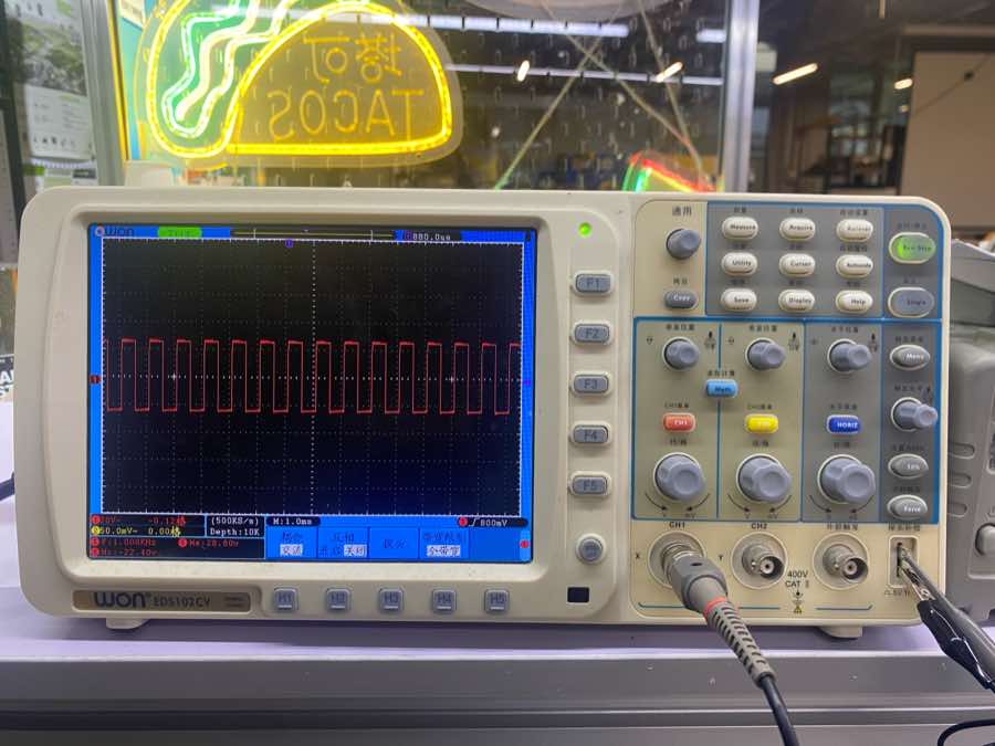
What is an oscilloscope?
An oscilloscope is a versatile electronic measuring instrument. It converts invisible electrical signals into visible images, allowing people to study the changing processes of various electrical phenomena. Simply put, it acts like a "video camera that records voltage changes over time."
How does it work?
The core mission of an oscilloscope is to graph the relationship between Voltage and Time.
-
Acquisition: The probe connects to the circuit and captures the voltage signal.
-
Conditioning & Sampling: Internal amplifiers adjust the signal size, then an ADC (Analog-to-Digital Converter) converts the continuous analog voltage into a stream of digital data.
-
Storage & Processing: This data is stored in memory and processed by a microprocessor (calculating frequency, peak values, etc.).
-
Display: Finally, it plots the graph on the screen, where the horizontal axis (X-axis) represents time and the vertical axis (Y-axis) represents voltage amplitude.
Primary uses
-
Waveform Analysis: Observing if a signal has the expected shape (e.g., sine wave, square wave).
-
Parameter Measurement: Automatically measuring frequency, period, peak-to-peak voltage ($V_{pp}$), duty cycle, etc.
-
Troubleshooting: Looking for noise, voltage spikes, or signal distortion in a circuit.
-
Protocol Decoding: Advanced oscilloscopes can decode communication protocols like I2C, SPI, and UART to verify data integrity.
-
Timing Comparison: Comparing the time difference between two or more signals (e.g., trigger vs. response).
Main parameters
| Term | Definition | Why it Matters |
|---|---|---|
| Bandwidth | The maximum frequency range at which the oscilloscope can accurately measure signals, typically measured in Megahertz (MHz). | Determines whether you can see high-speed signals clearly without distortion. |
| Sample Rate | The number of times per second the oscilloscope captures or samples the input signal, measured in Samples per second (S/s). | Higher sample rates provide a more detailed and accurate reconstruction of the waveform. |
| Trigger | A function that synchronizes the horizontal sweep of the oscilloscope to a specific point on the signal. | It stabilizes a repeating signal on the screen so it doesn't appear to be "drifting" or "jumping." |
| Vertical Sensitivity | The scale of the voltage axis, usually expressed in Volts per division (V/div). | Allows you to zoom in or out on the amplitude (height) of the signal. |
| Time Base | The scale of the horizontal axis, usually expressed in Seconds per division (s/div). | Allows you to speed up or slow down the view to see individual cycles or long-term trends. |
| Rise Time | The time it takes for a signal to transition from a low value (usually 10%) to a high value (usually 90%). | Critical for digital electronics to ensure pulses are sharp enough for the logic gates to read. |
| Memory Depth | The total number of data points the oscilloscope can store in a single acquisition. | A deeper memory allows you to capture long periods of time while maintaining a high sample rate. |
| Input Coupling | The method used to connect the signal to the oscilloscope (AC, DC, or Ground). | DC shows the whole signal; AC blocks the DC offset to let you focus on small ripples or noise. |
Learn the display panel
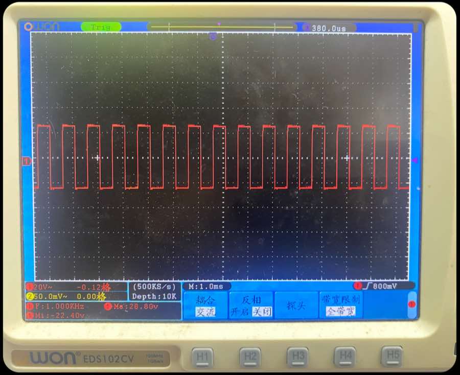
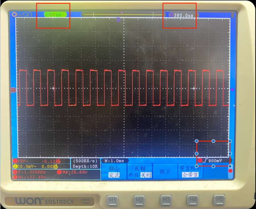
Part 1
| Information on the panel | Clarification |
|---|---|
| F: 1.000 KHz | The frequency of the signal is 1 kHz |
| Ma: 28.80 V | The max voltage of the signal is 28.8 V |
| Mi: -22.40 V | The minimal voltage of the signal is -22.4 V |
| VPP (Peak-to-Peak) (not in the image) | Ma − Mi = 28.8 − (−22.4) = 51.2 V |
Part 2
| Information on the panel | Clarification |
|---|---|
| 20 V~ | In the vertical, each row means 20 V; ~ means AC coupling; so the voltage is around 2.5 rows, it is around 50 V |
| M: 1.0 ms | In horizontal, each column means 1.0 ms. The cycle of the wave is almost 1.0 ms, therefore the frequency is 1/1.0 ms = 1 kHz, same as the data above |
| 500 ks/s | Sample rate, 500k data points every second |
| Depth 10K | Memory depth; captures and stores 10,000 sampling points in a single acquisition cycle |
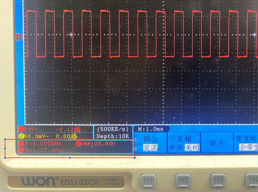
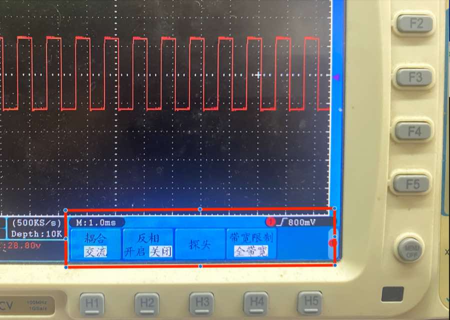
Part 3
| Information on the panel | Clarification |
|---|---|
| 耦合 (Coupling) | AC coupling, means remove the DC part of the signal |
| 反相 (invert) | If turned on, the wave will invert |
| 探头 | NA |
| 带宽限制 (bandwidth limit) | Full bandwidth, show all the bandwidth, no limit; there is another option of 20 MHz |
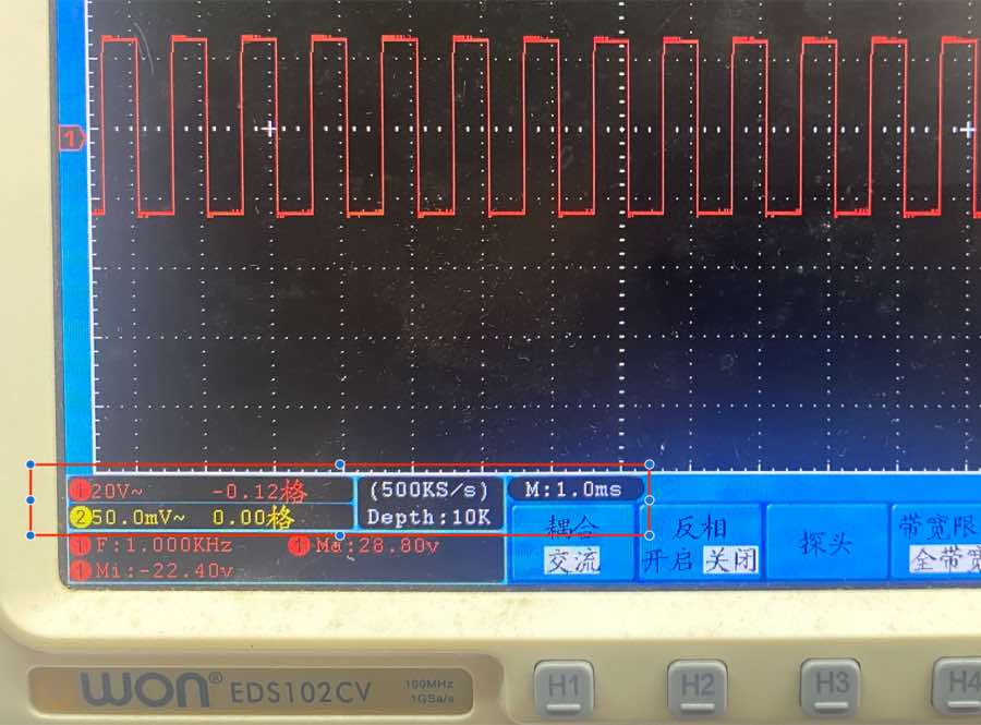
Part 4
| Information on the panel | Clarification |
|---|---|
| Trig | The signal has been captured and in the best condition to analyze |
| T 380.0 us | Horizontal delay — shows the time offset between the trigger point and the screen center |
| 800 mV | Trigger level — set the voltage threshold to stabilize the waveform. In the picture, the wave is happening at 800 mV |
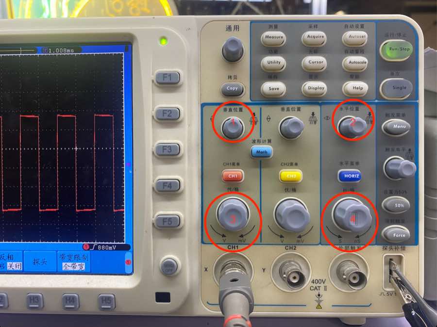
Control panel
| Button in the picture | Clarification |
|---|---|
| 1 | Move the wave vertically, making it easier to calculate the voltage |
| 2 | Move the wave horizontally; the trigger time will be adjusted accordingly |
| 3 | Adjust voltage of each row to find the best analysis status |
| 4 | Adjust the time of each square to find the best analysis status |
Multimeters — HuaShengChang DT660B
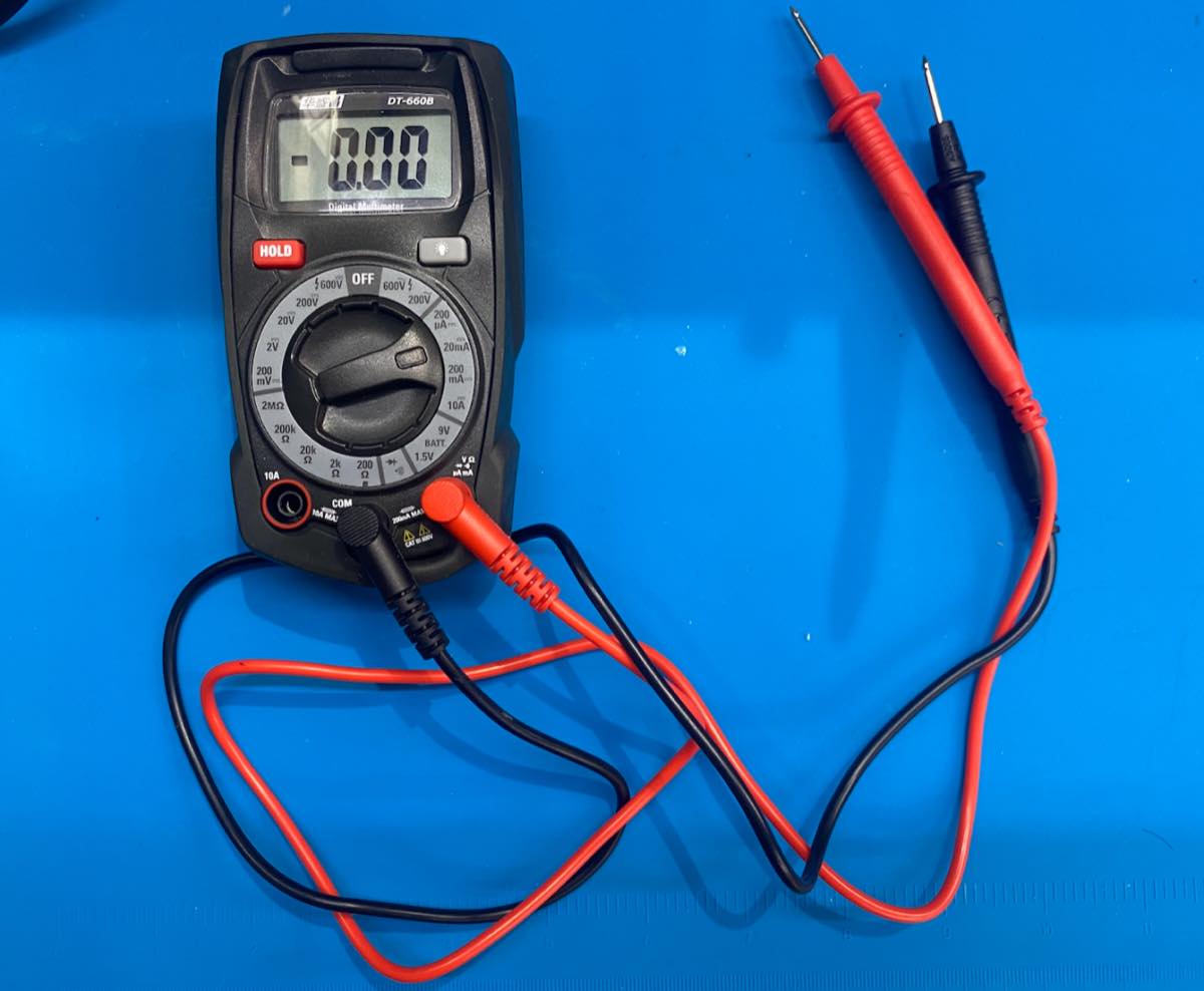
| Section | Symbol/Position | Description |
|---|---|---|
| DC Voltage | V… (200m to 600V) | Used for batteries and DC circuits. Select a range higher than your target voltage. |
| AC Voltage | V∼ (200 to 600V) | Used for mains electricity (wall outlets). Always use 600V for safety when testing outlets. |
| DC Current | A… (μA to 10A) | Measures current. Caution: Must move the red probe to the 10A port for high current. |
| Resistance | Ω (200 to 2MΩ) | Measures resistors. The continuity icon is for continuity (beeping). |
| Battery Test | BATT (1.5V / 9V) | A specialized mode to test small batteries under a slight load. |
| Diode Test | →+ | Checks if a diode is working. |
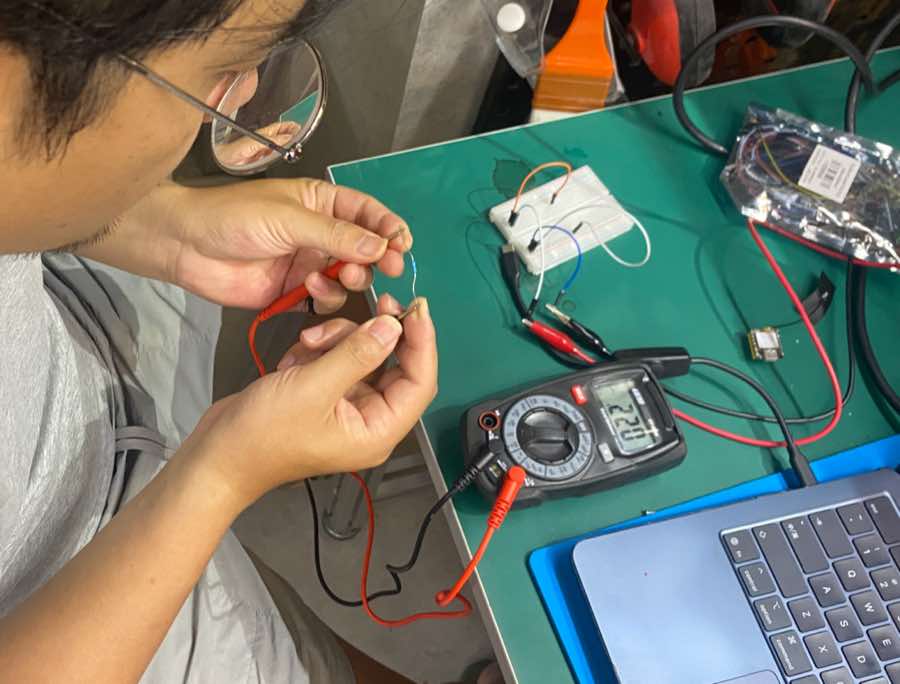
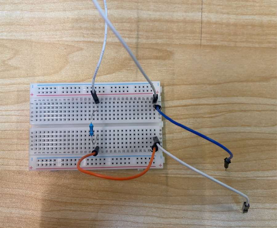
For measurement, I built a simple circuit on a breadboard. I use the power supply with 3.3 V.
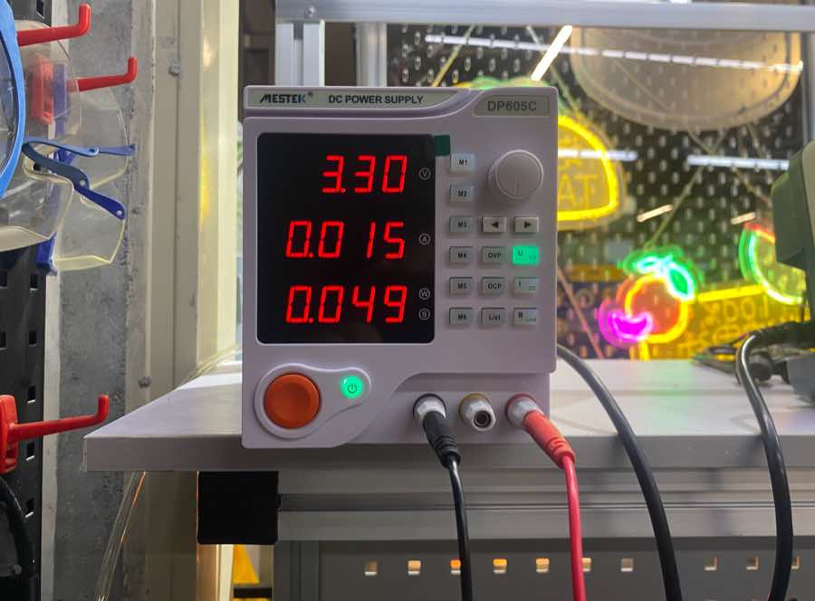
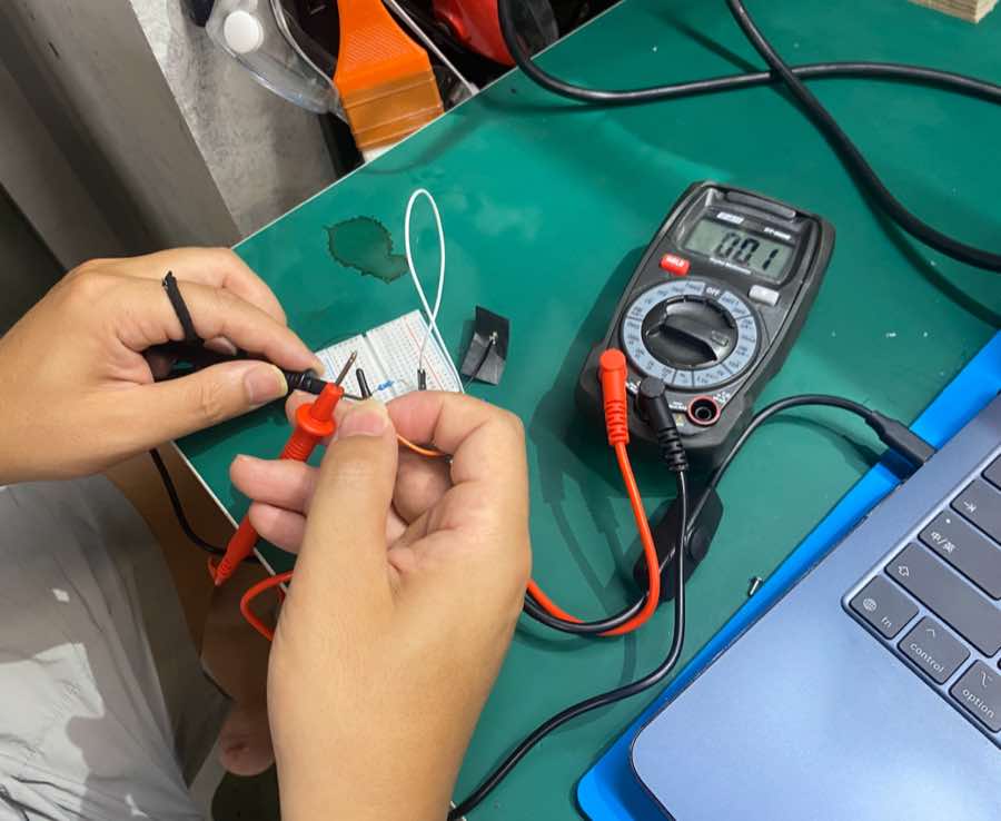
Measure current: the current is 0.01 A. There is a difference from 0.015 A; it cannot show more digits.
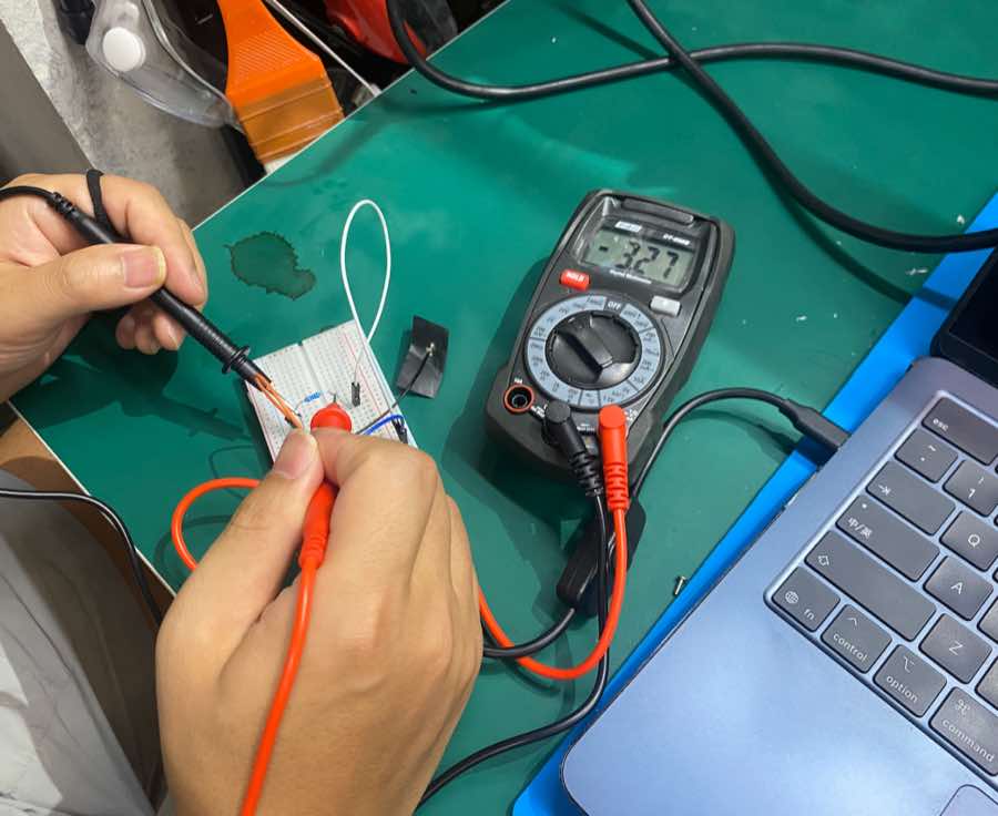
Measure voltage: the voltage is 3.27 V, close to the power supply 3.3 V.
Measure resistor: the resistor is 220 Ω.