Week 7 Computer-controlled machining
Group assignment
- Do your lab's safety training
- Understand machine safety operating procedures (emergency stop, protective guards, operation process).
- Test the machine
- Runout: Eccentricity of the spindle/tool during rotation.
- Alignment/Fixturing: Whether the material is firmly fixed, coordinate system calibration.
- Speeds and Feeds: Cutting parameters for different materials (wood, plastic, modeling board, etc.).
- Materials and Toolpaths: Cut small samples to check surface quality and dimensional accuracy.
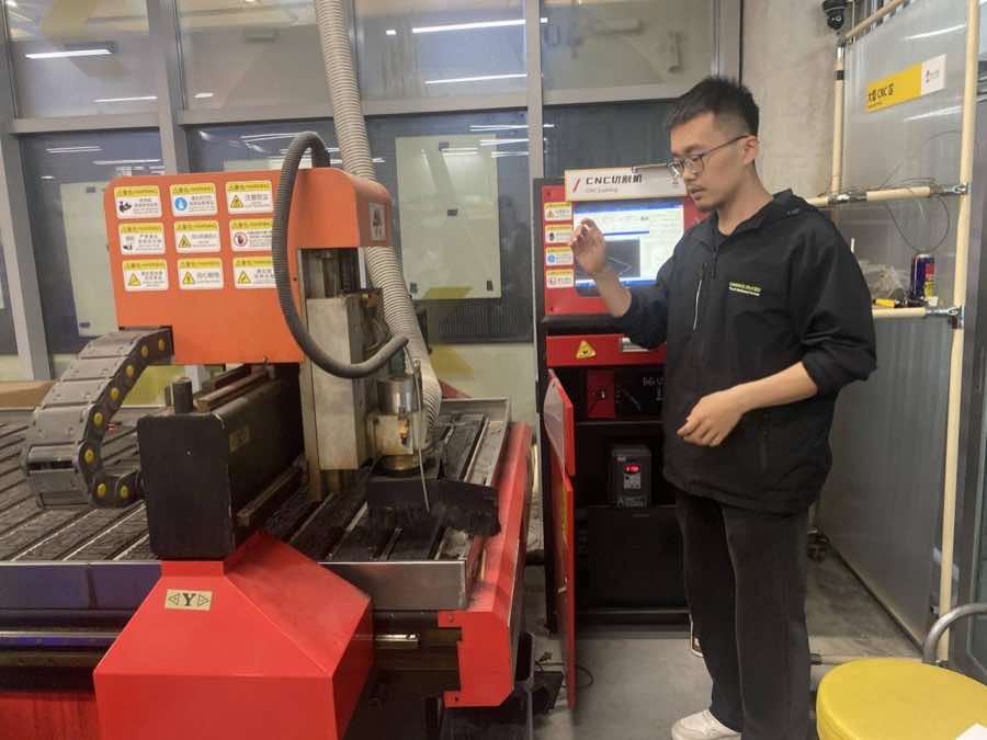
CNC Safety training
Matthew is doing the safety training to us.
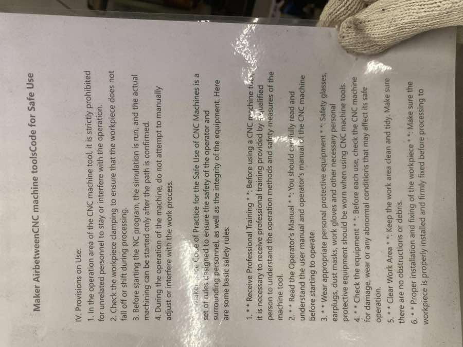
Cautions and safety use
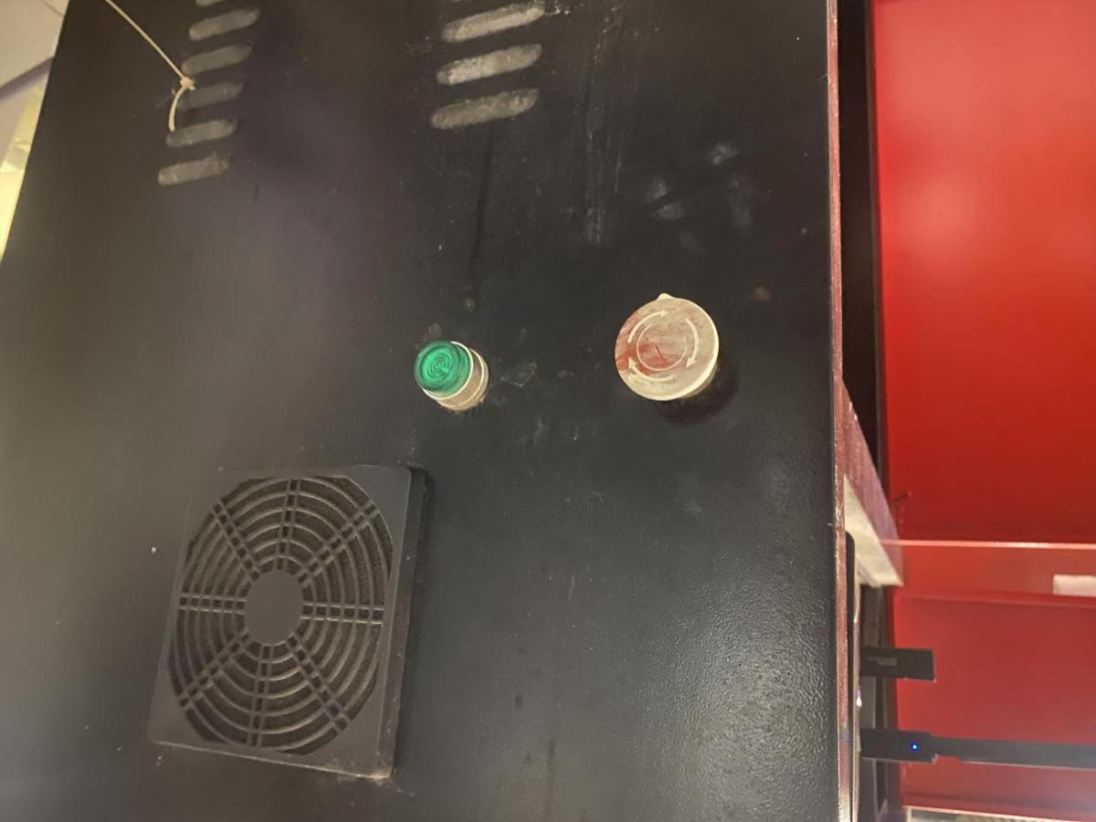
Emergency stop button
Operation Demonstration
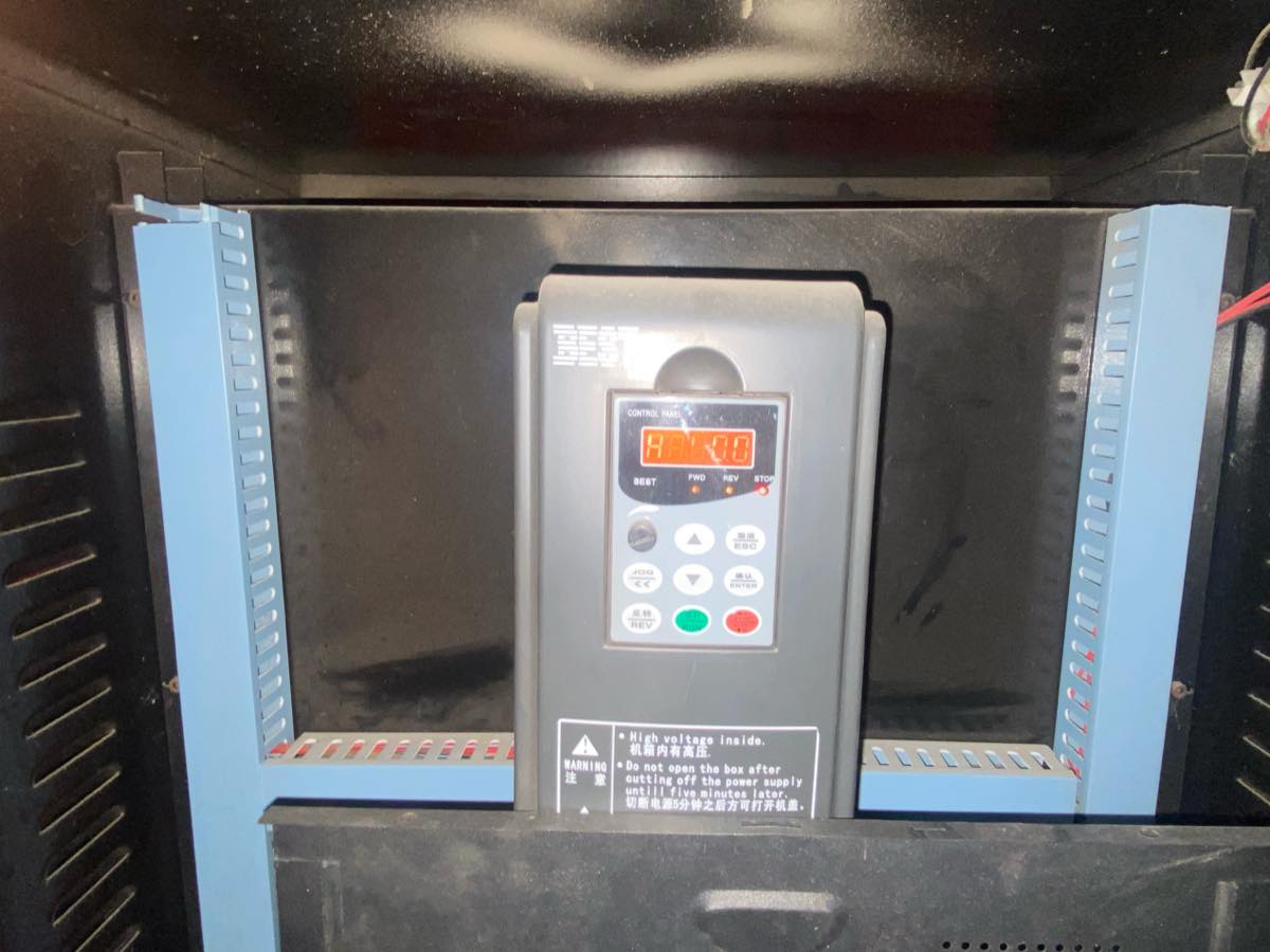
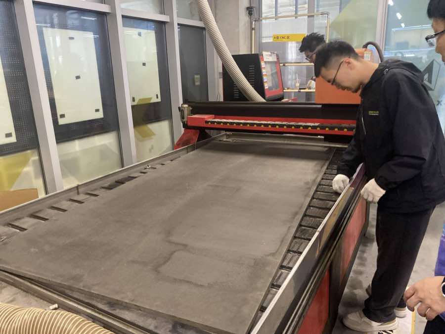
Step 1 turn on the machine
Step 2 Clean the milling machine, make sure no other stuff on working place; then place the wood board to the milling machine
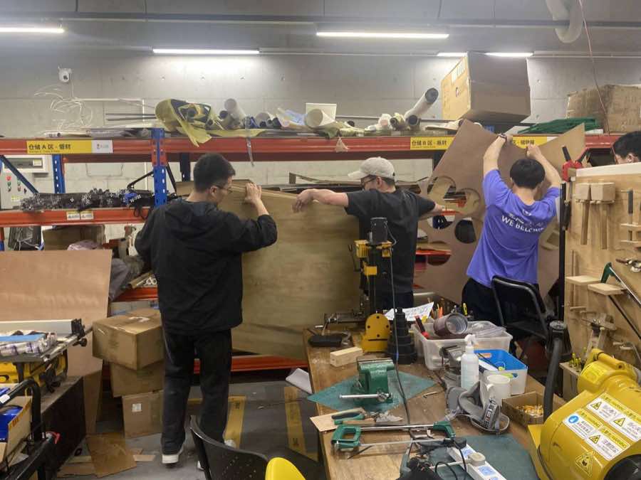
The spec. of the board :1500 mm × 2400 mm × 18 mm.
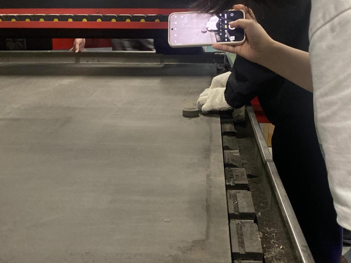
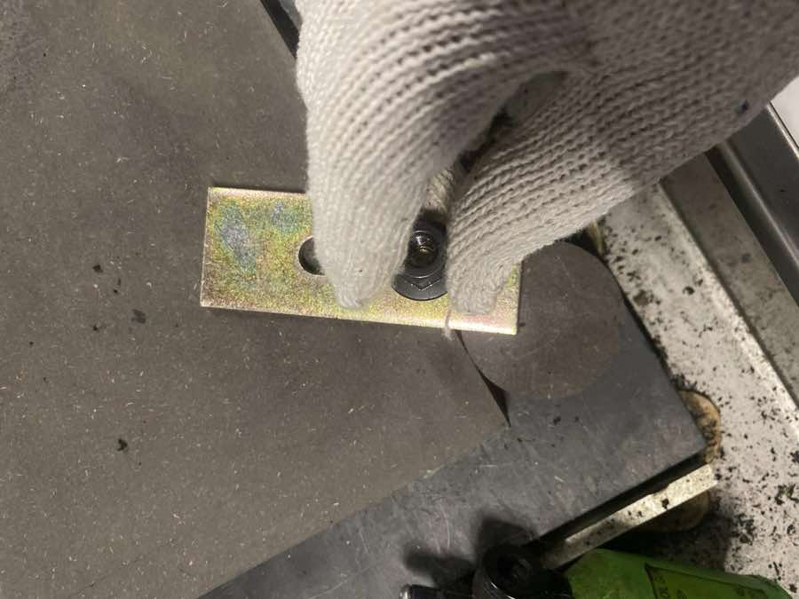
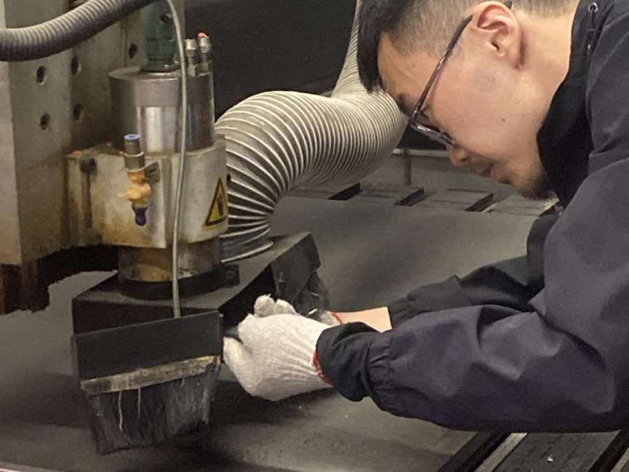
Step 3 Fix the board on the milling machine, as below, use a Circular gasket as support to fix it up tightly
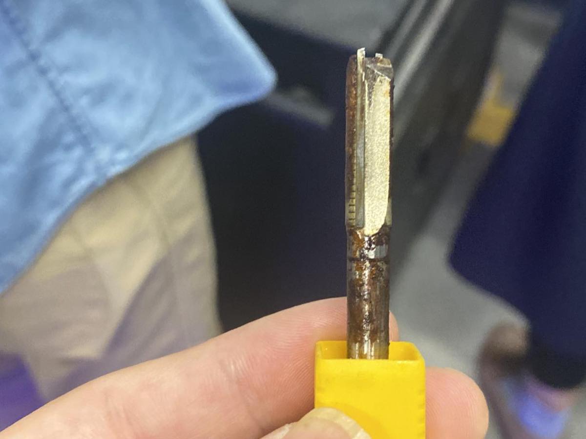
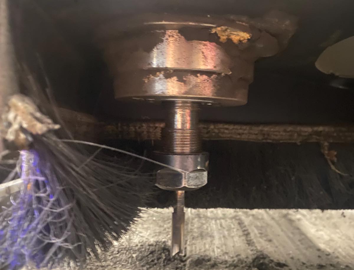
Step 4 Milling cutter and assembling milling cutter
Spec of milling cutter, diameter of the cutter is 8mm
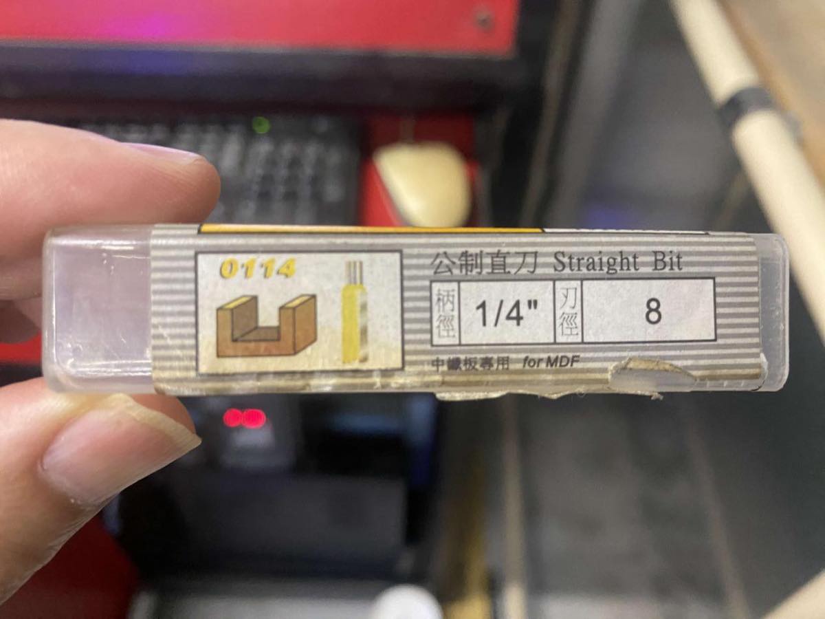
Open the box of milling cutter

Assemble the cutter
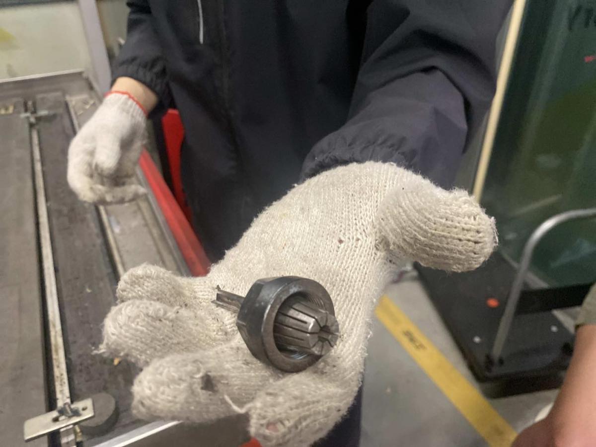
Put it back and close the box.
Step 5 Zero point setting
Simulation on the computer of the zero point
Step 6 Start cutting
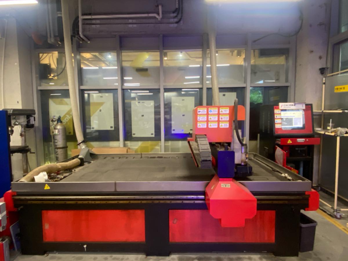
CNC Equipment Specs.
| Specification | Details |
| Manufacturer | Tiancheng Xinli CNC |
| Model | 3STX-1325A |
| Workbench Size | 1450mm × 2900mm |
| Processing Range | 1300mm × 2500mm |
| Z-axis Travel | 180mm |
| Feed Height | 200mm |
| Positioning Accuracy | ±0.15/300/mm |
| Spindle Speed | 0~24000 (r/min) |
| Engraving Commands | G Code, UPP, mmg, nc |
| Idle Speed | 0~20000mm/minute |
| Processing Speed | 0~15000/minute |
| Resolution | 0.00625/pulse |
| Tool Diameter | 3.175mm, 4mm, 6mm, 8mm, 10mm, 12.7mm |
| Spindle Power | 3KW water-cooled |
| Cooling System | Water pump |
| Actual Weight | 2200kg |
| Machine Power | 380V 50Hz (built-in switching power supply) |
Individual assignment
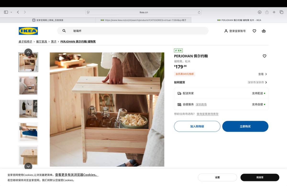
I didn't have a good idea about design, but I know where I can find a good design, when I browse the IKEA, the bench looks good and practical. Maybe I could make a similar one in this assignment, without screws.
Make all parts on Onshape
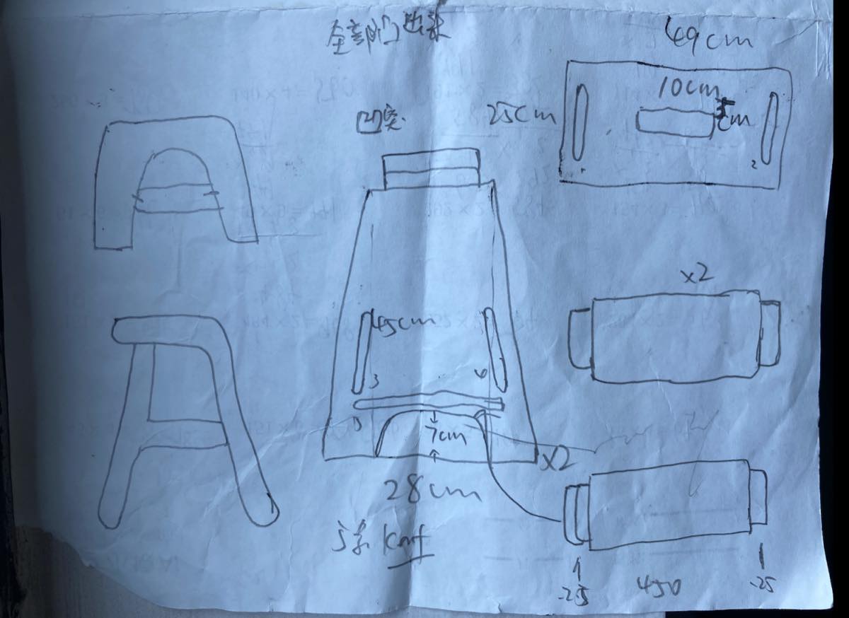
Before starting work on Onshape, I draw draft first.
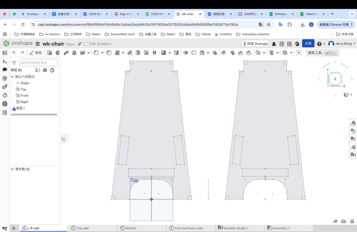
Step 1 Side Legs
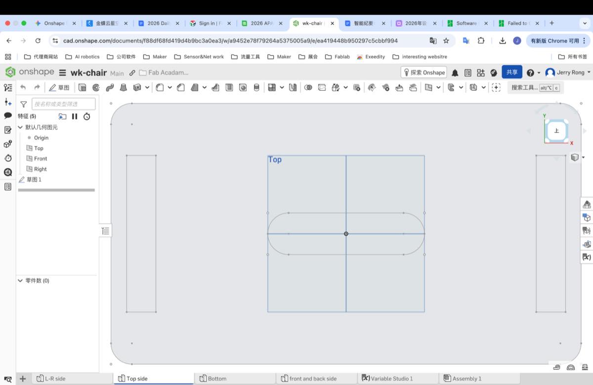
Step 2 Top plate
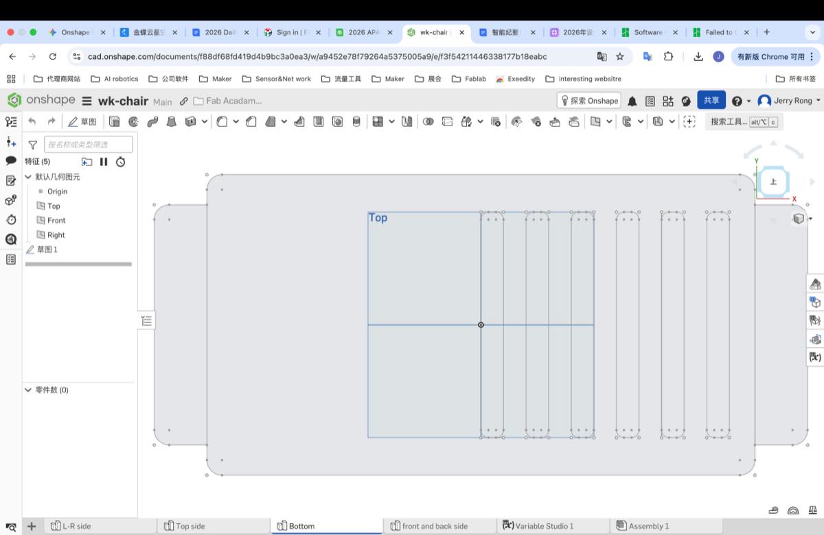
Step 3 Bottom plate
Step 4 Front and back plate
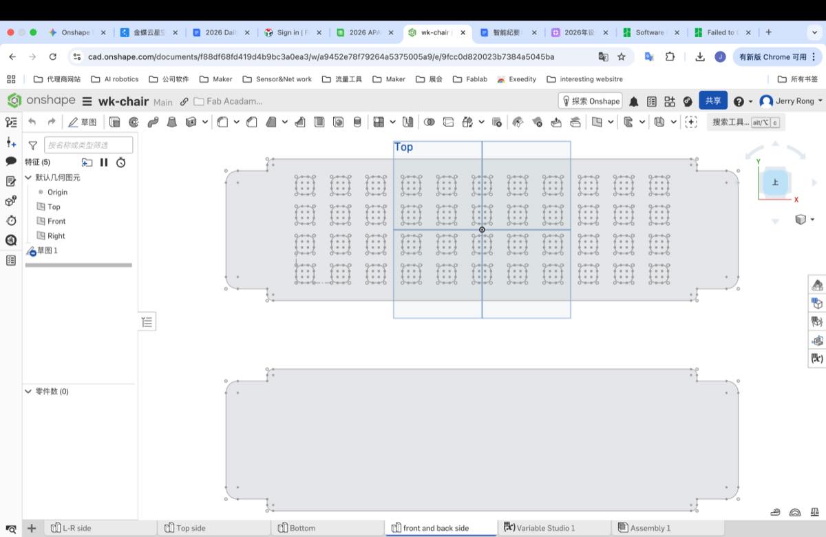
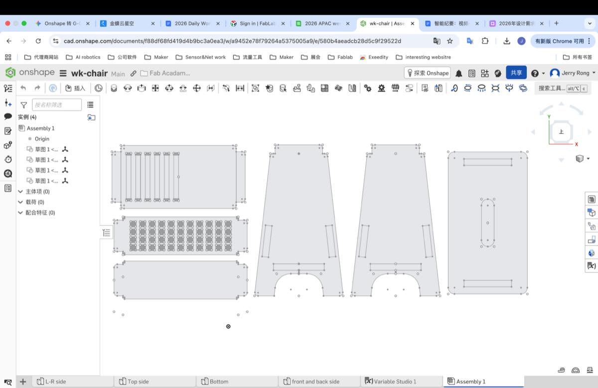
Step 5 Assemble them together ( in one file)
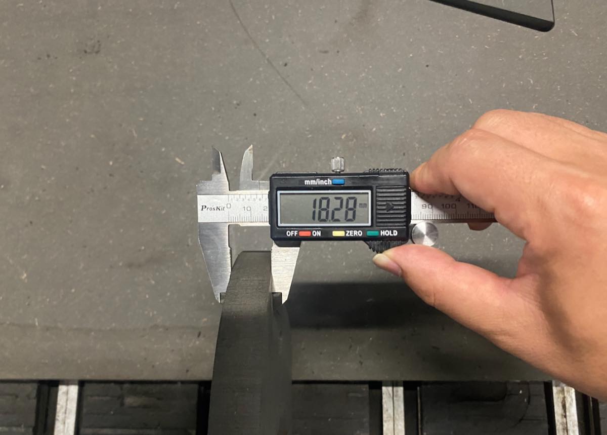
Step 6 The thickness of the plate is 18.28mm, adjust the width of the kerf to 18.28 + 2 = 20.28 mm; 2 mm is an experienced value from our Mentor, Matthew.
Output the file - Week 7 assignment - Bench
Step 7 Change the format to G-code
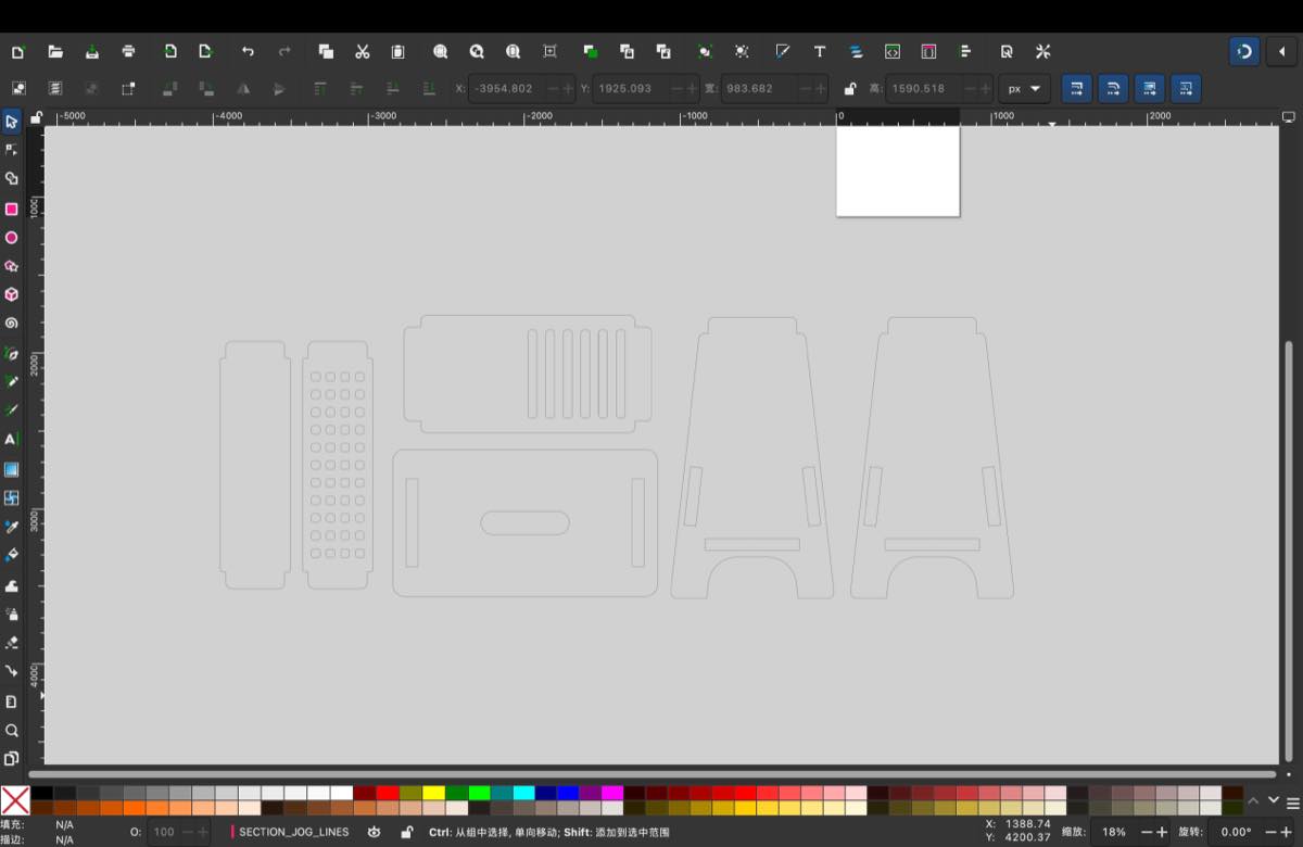
Add all four parts to Inkscape or LaserMaker as below. According to my experience, I feel both of them can collect them together, just use copy and paste. But when it comes to output the file, I will recommend LaserMaker. When I use the Inkscape, I didn’t find the right format, or some part will be hidden or lost. But LaserMaker works more smoothly.
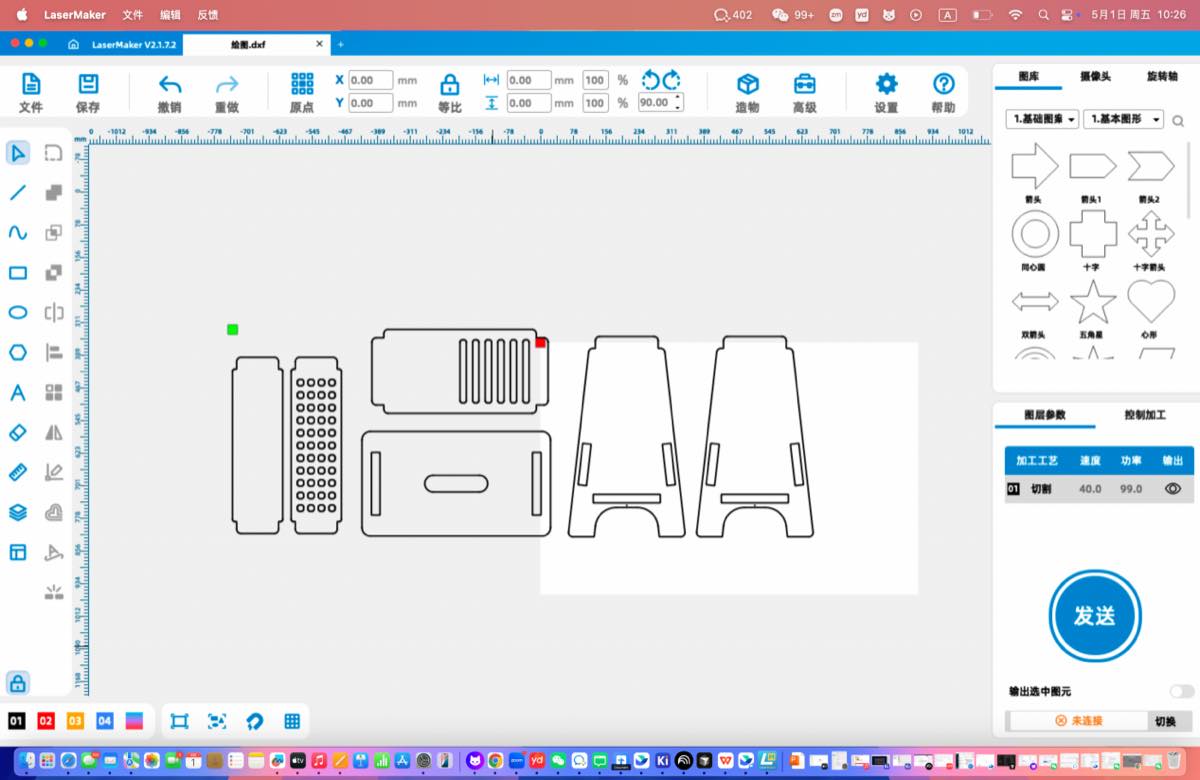
The dxf file as attached.
DXF file: Week7-assignment-bench.dxf
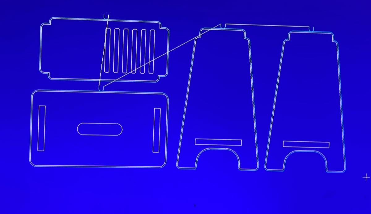
Step 7 Convert the dxf to G-code.
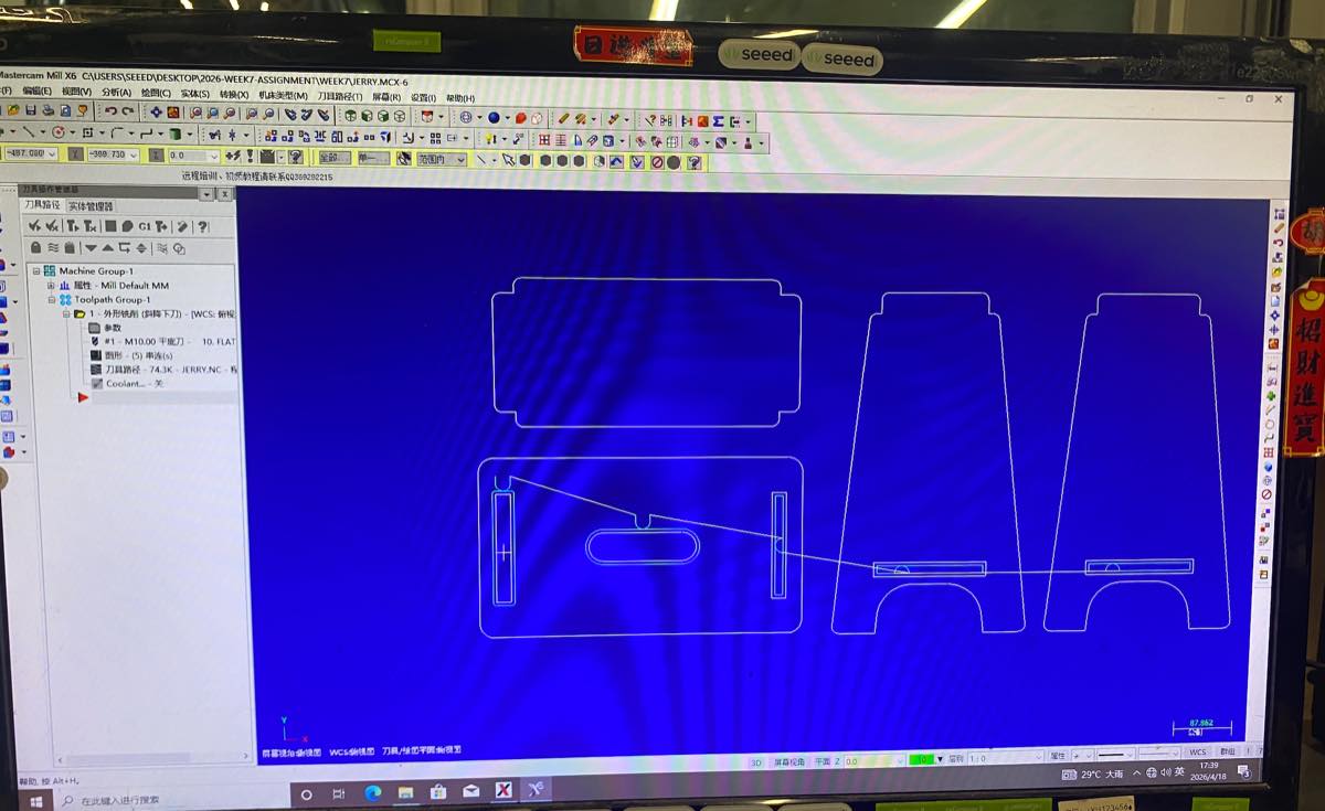
Due to the size is somewhat large, we adjust the parts of the bench, to make more suitable for the current CNC machine to proceed, removed 2 parts, and remove some internal shape. It is a pity, but I already learned a lot.
G-code file: Week7-assignment-bench.NC
Running CNC machine to cut the bench
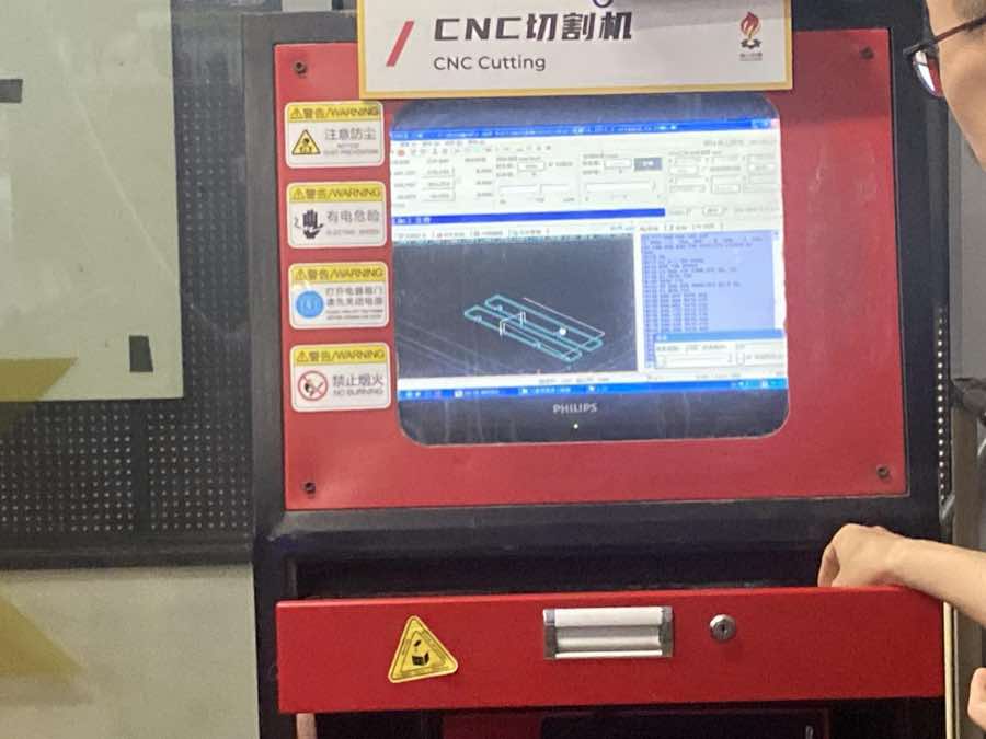
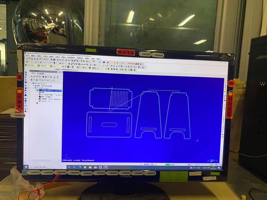
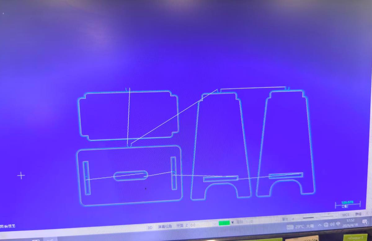
Step 1 Upload the G-code file with a USB drive, and open it from MasterCam Mill X6
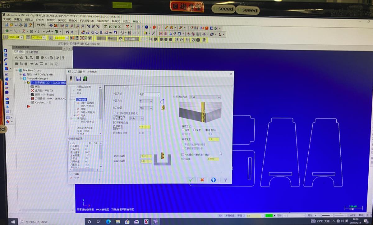
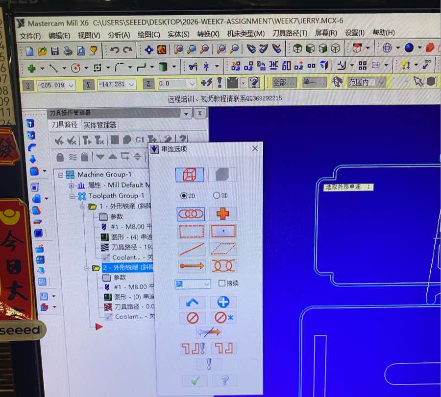
Step 2 Setting of the track of the drill to cut the inner parts
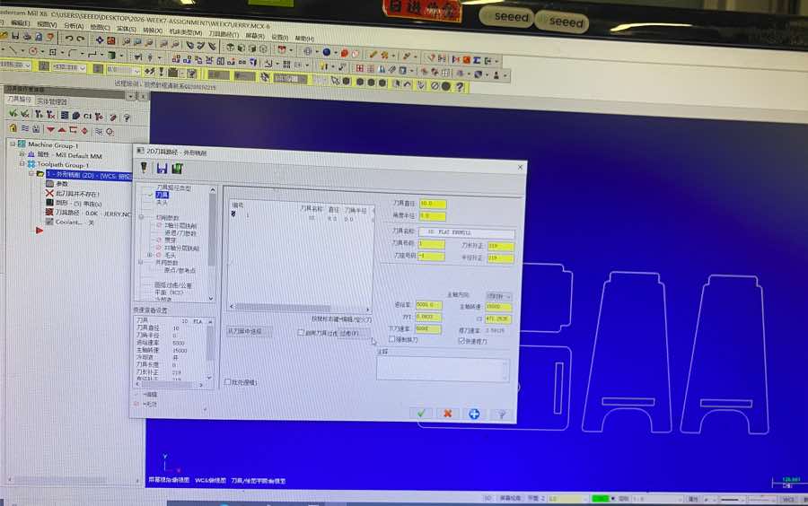
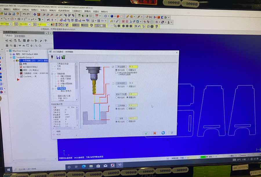
Step 3 The setting of track of drill to cut the outer side.

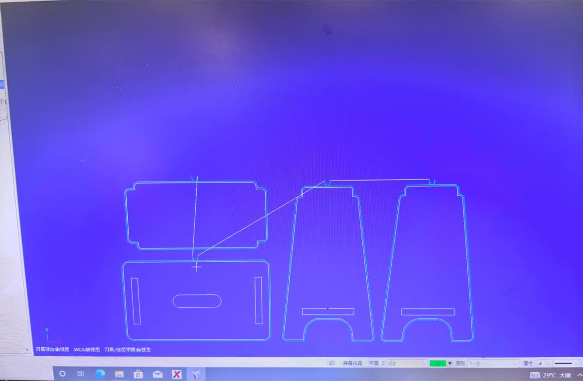
I finish the setting of the track of drill
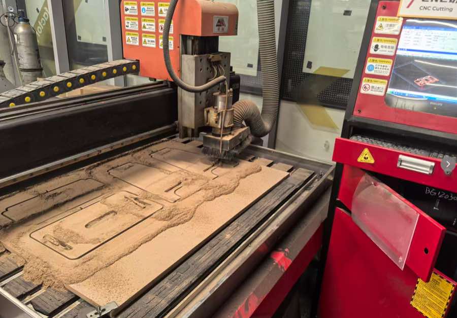
Step 4 Start the CNC cutting, see the video.
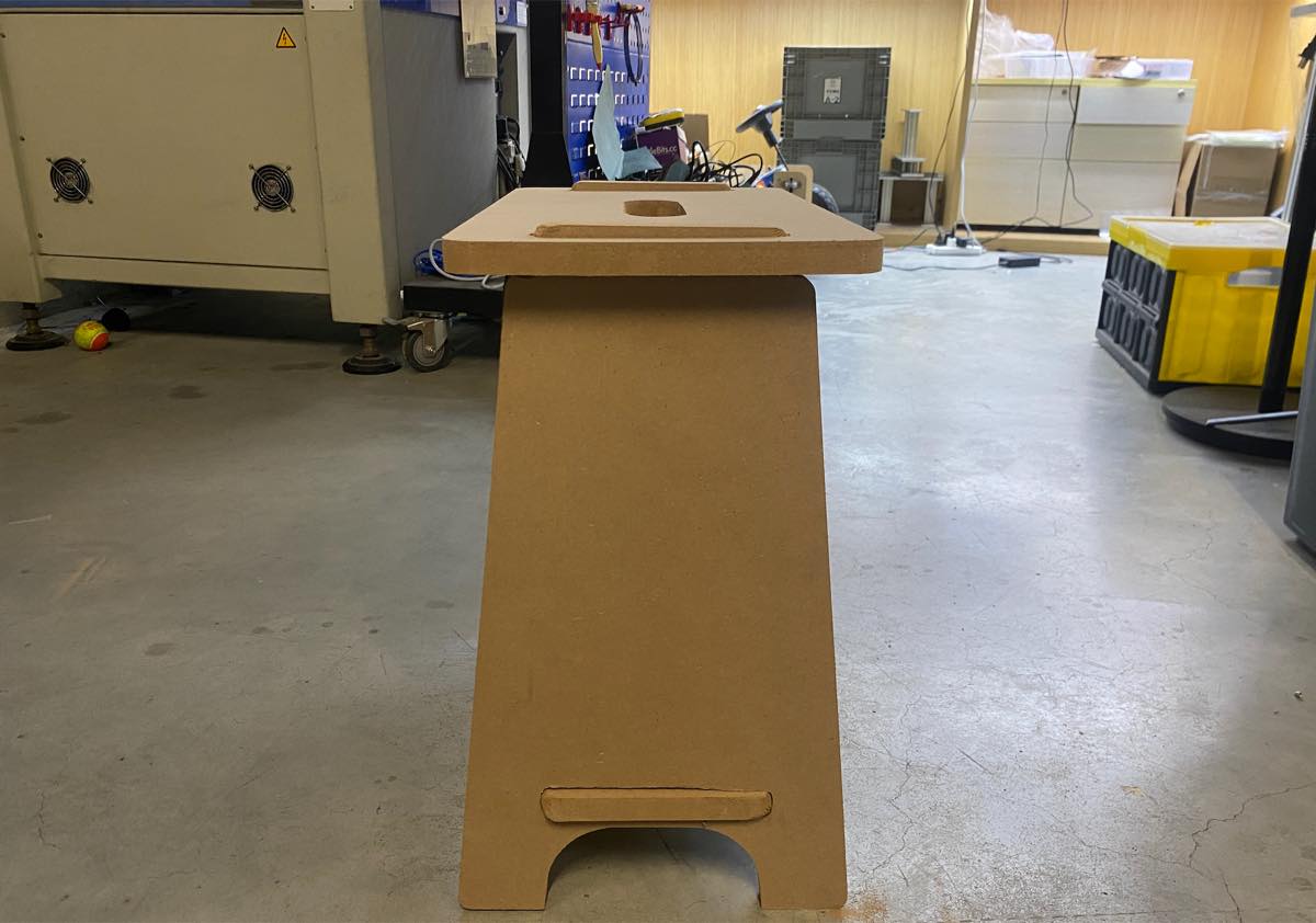
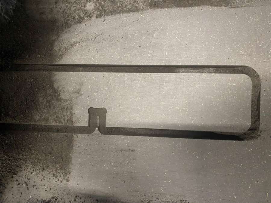
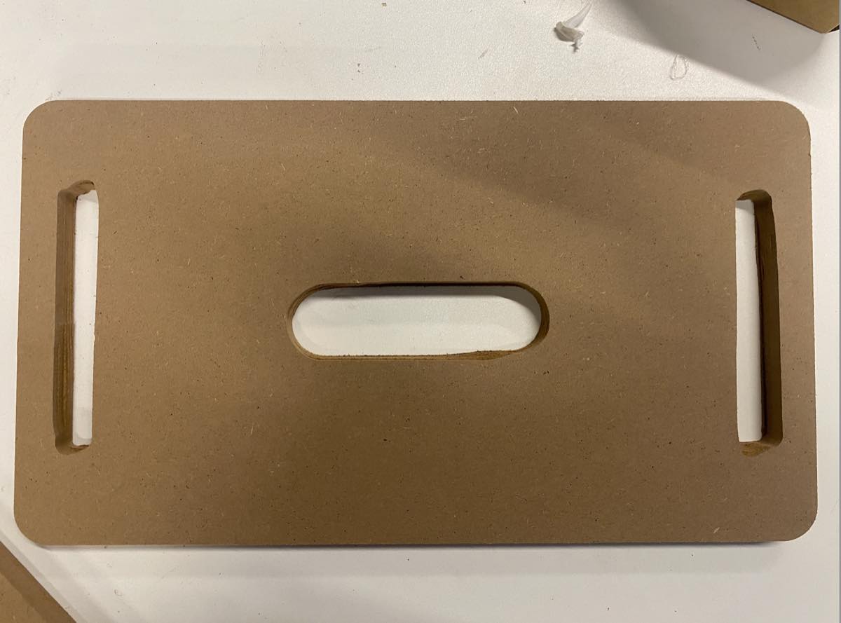
Step 5 Finish, and got the 4 parts.
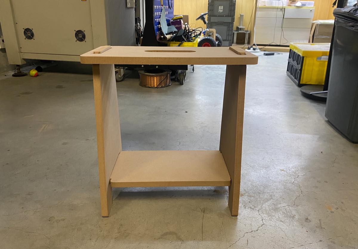
Step 6 Assembly
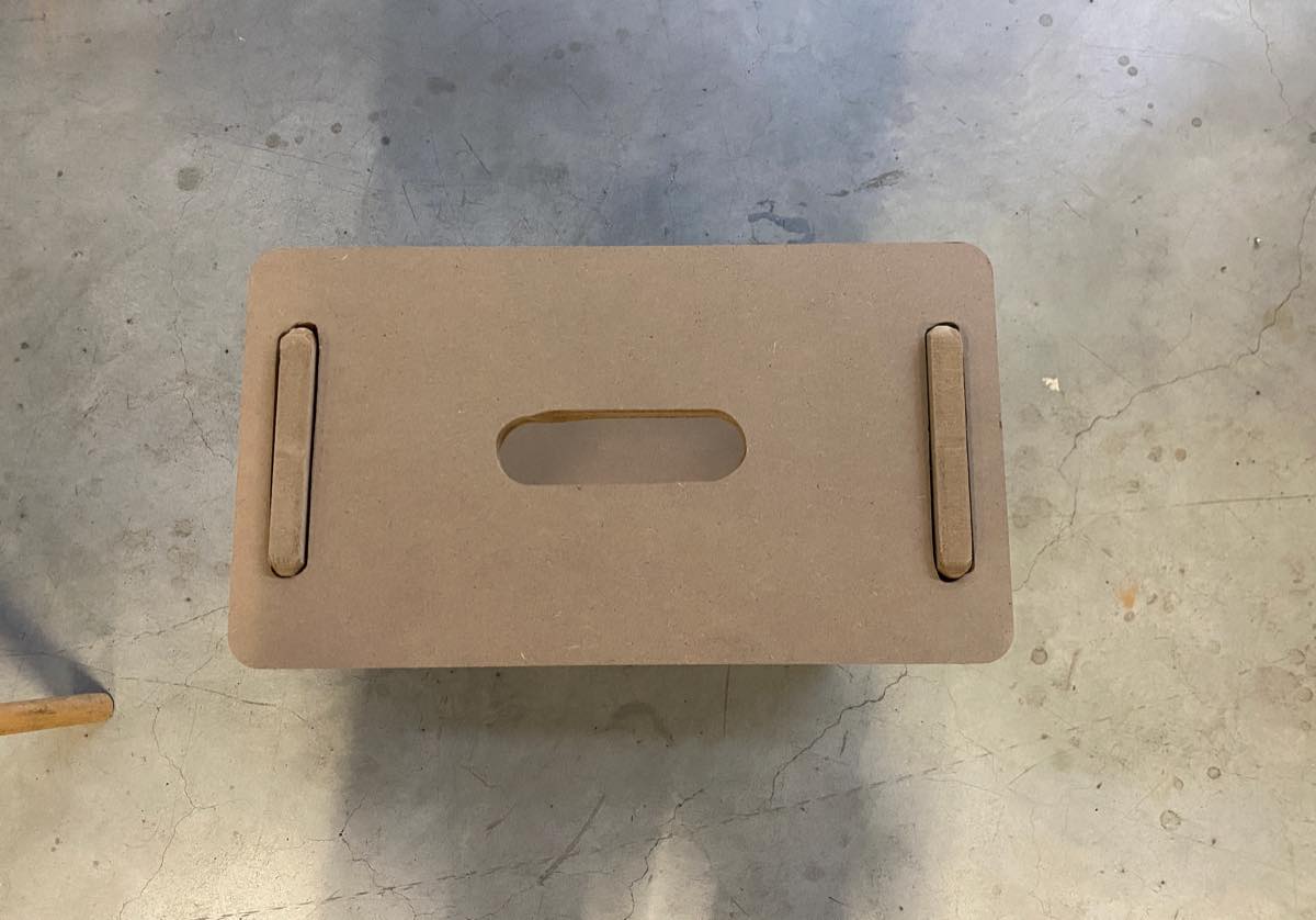
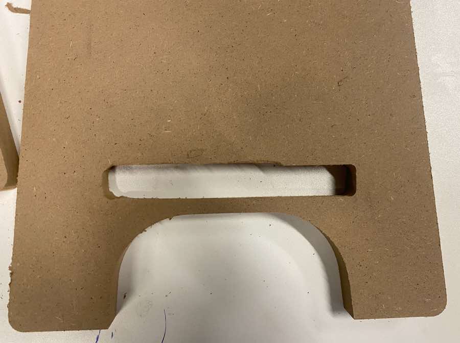
For the cutting of these inner “rectangle” is not good enough, we can find the shape is somewhat slightly deformed. I feel it is because it is too narrow for the machine or the drill.
The assembled bench, as below