Electronics Production
Here is the link to our Group assignment: Week 8 Group Assignment
PCB Production
Design rules used for milling
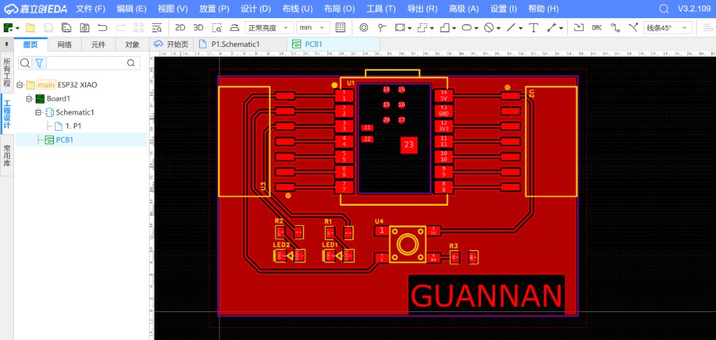
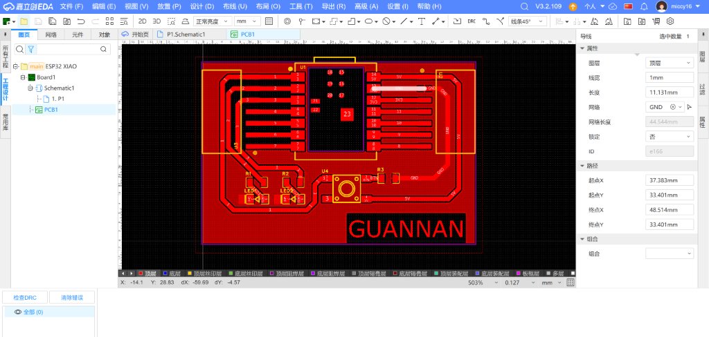
Before milling I set explicit rules in LCEDA and matched them to the Mods PCB workflow. The first board failed because traces were too thin; I increased width and re-exported Gerber/PNG.
| Rule | Value | Where set / verified |
|---|---|---|
| Minimum trace width (EDA) | 0.8 mm | LCEDA PCB layout — after first failed thin-trace mill (PCB_design.jpg); some nets (e.g. GND) at 1.0 mm |
| Minimum clearance (EDA DRC) | 0.8 mm | LCEDA DRC — must pass before export (DRC_check.jpg) |
| Trace mill tool | 1/64″ end mill, Ø 0.4064 mm; V-bit 40° tip 0.13 mm | Mods mill 2D PCB — Generate_CNC_01.jpg |
| Trace cut depth | 0.1016 mm (one pass) | Mods trace settings |
| Outline mill tool | 1/32″ end mill, Ø 0.7938 mm | Mods outline — Generate_CNC_03.jpg |
| Isolation offsets | 4 offsets, stepover 0.5 | Mods raster 2D — effective clearance ≥ EDA 0.8 mm rule |
| Cut / plunge speed | 4 mm/s cut, 2 mm/s plunge; 10000 rpm spindle | Mods G-code post |
At first, I planned to use SnapmakerA350T CNC module to produce the PCB.
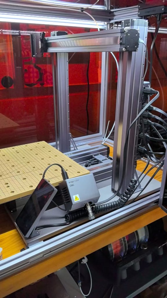
We did not find the clamp for the toolhead, so I purchased one from Taobao to solve the problem.
Then we had an issue with the software, Luban is the software for Snapmaker, but there was always some erros with the CNC module.
No matter we use a PNG file or a SVG file, the toolpath was not right.
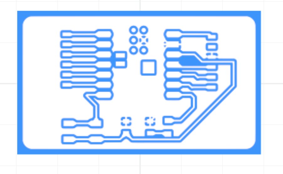
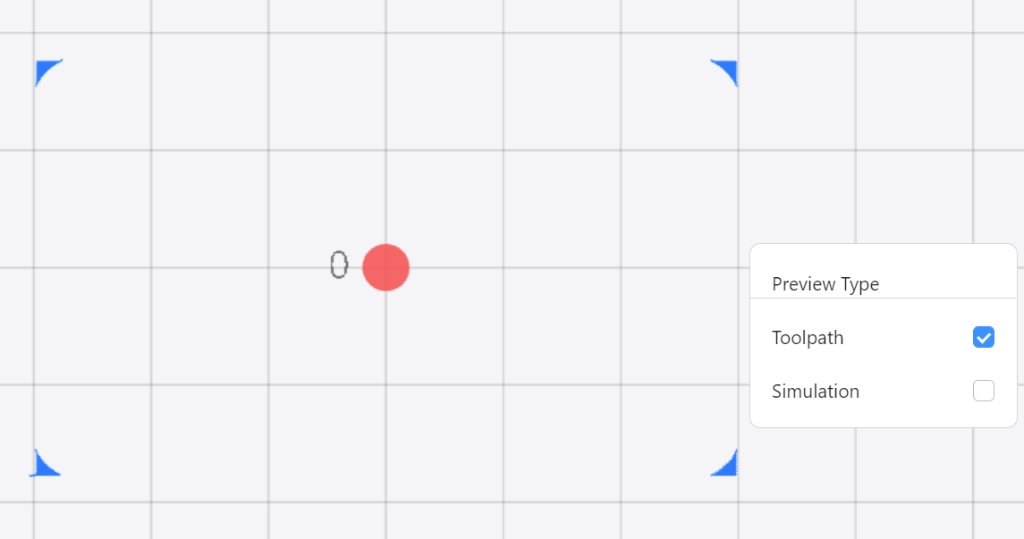
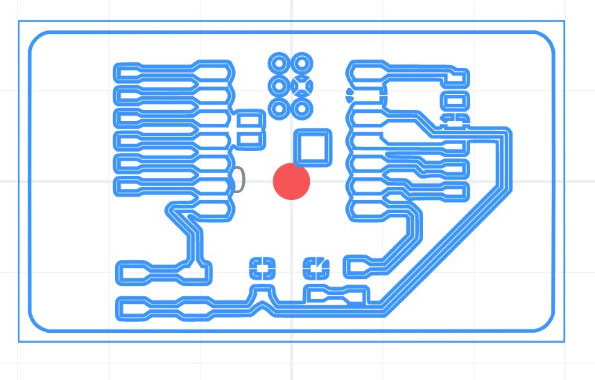
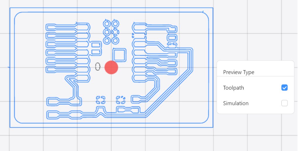
Then I used the tools recommended by our instructor. The first one was a tool convert Gerber files to PNG.
Here is the link to the tool: Gerber to PNG
Here is my Gerber files: Gerber_Guannan.zip
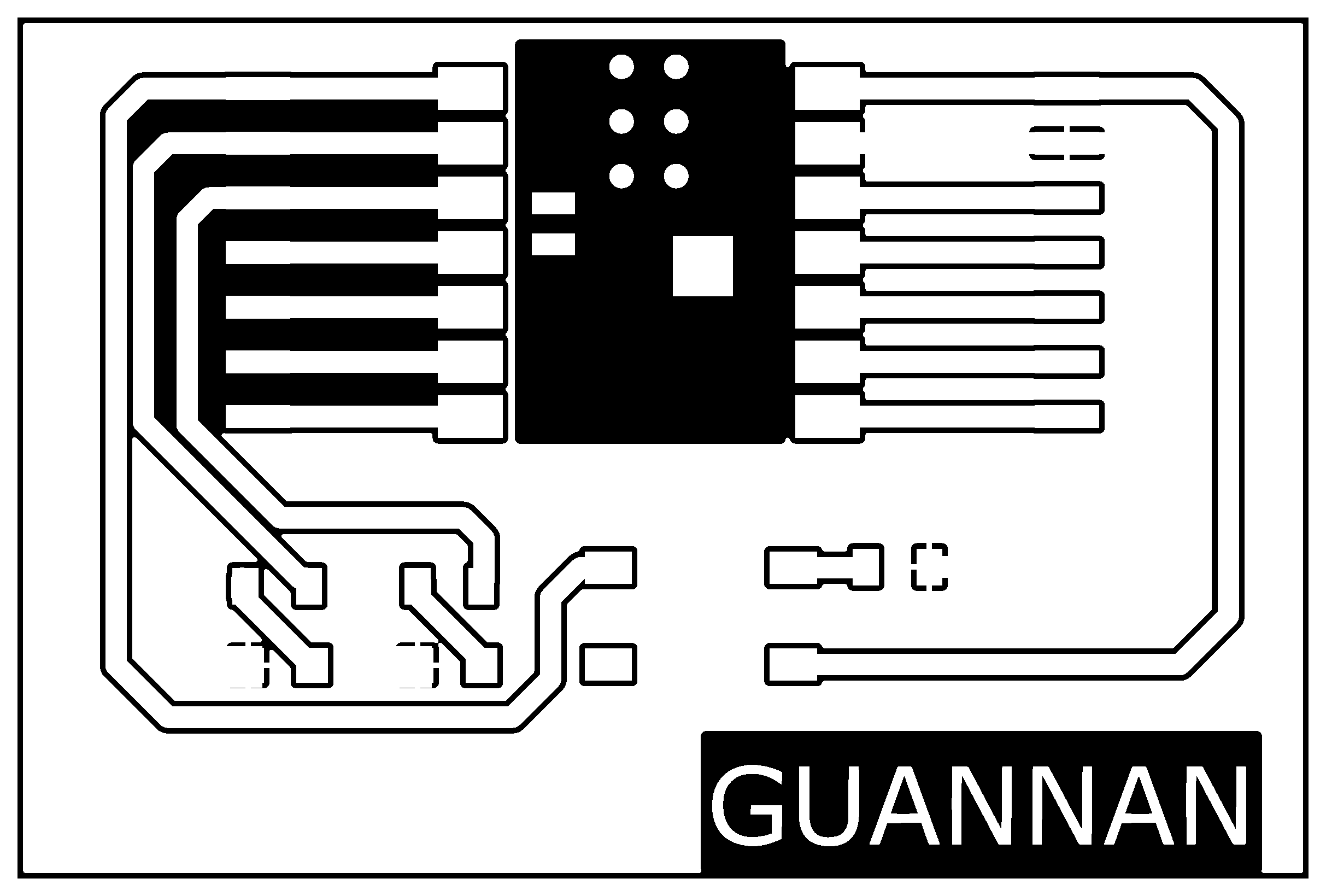
Traces and outline needed to be generated separately.

The second one was a tool which was easy to use tool for converting PNG files to NC files.
The tool is here: PNG to NC
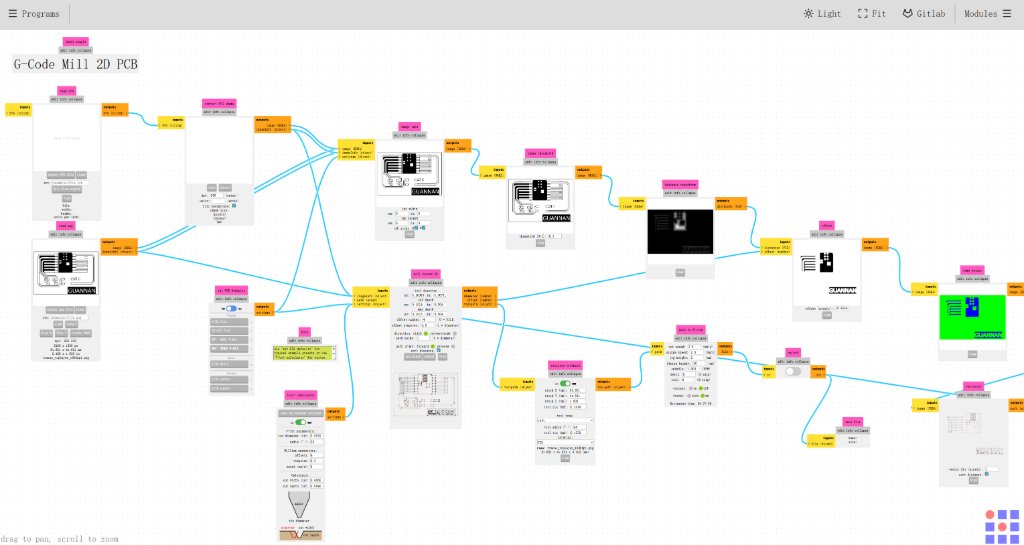
The tool provided an preview of the CNC result.
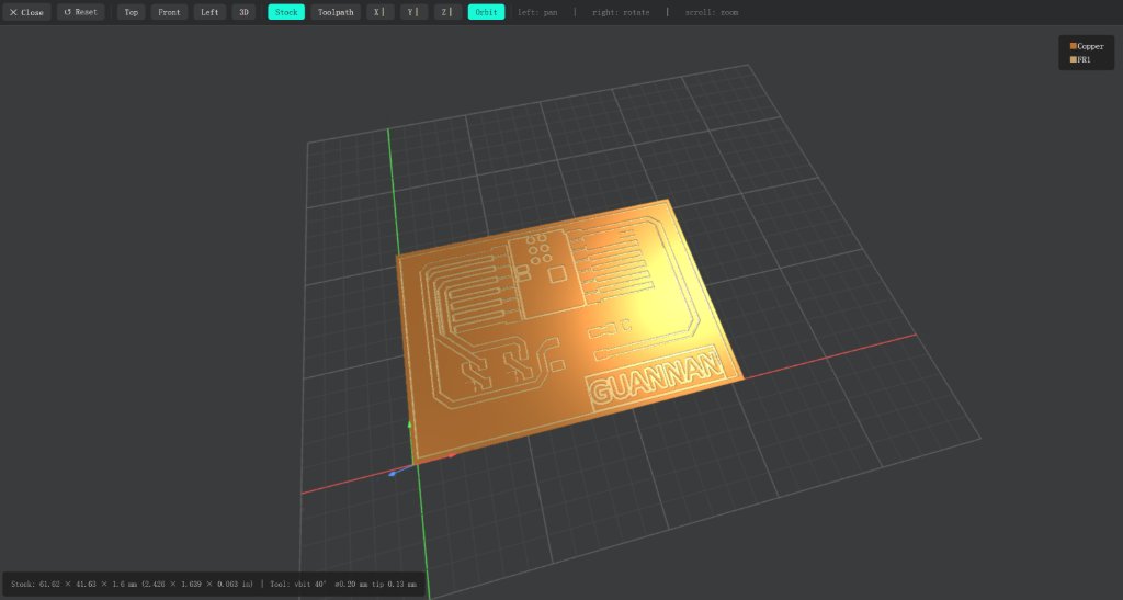
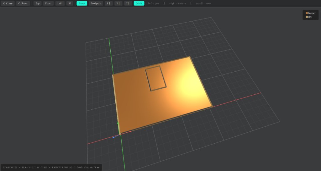
Then I exported the NC files (gcode files for CNC machine)
Here are the NC files: Trace_GN.nc and Outline_GN.nc
But the CNC machine we were using needed some special settings to make it working well.
I used the text editor Notepad++ to edit the NC files.
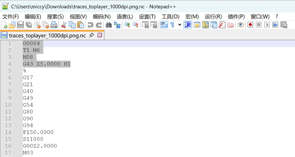
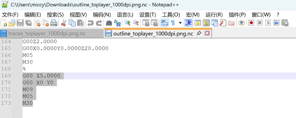
Then I copied the NC files to a USB stick and inserted it into the CNC machine.
This is the CNC machine we were using:
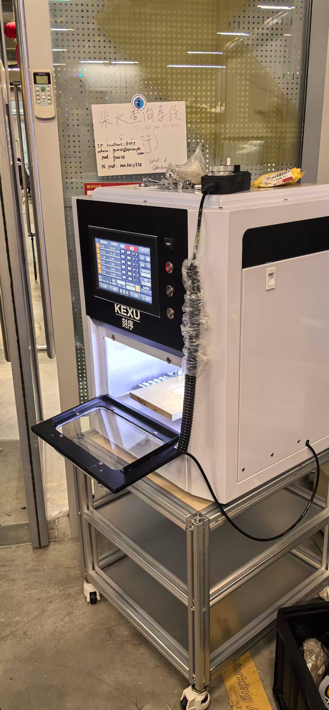
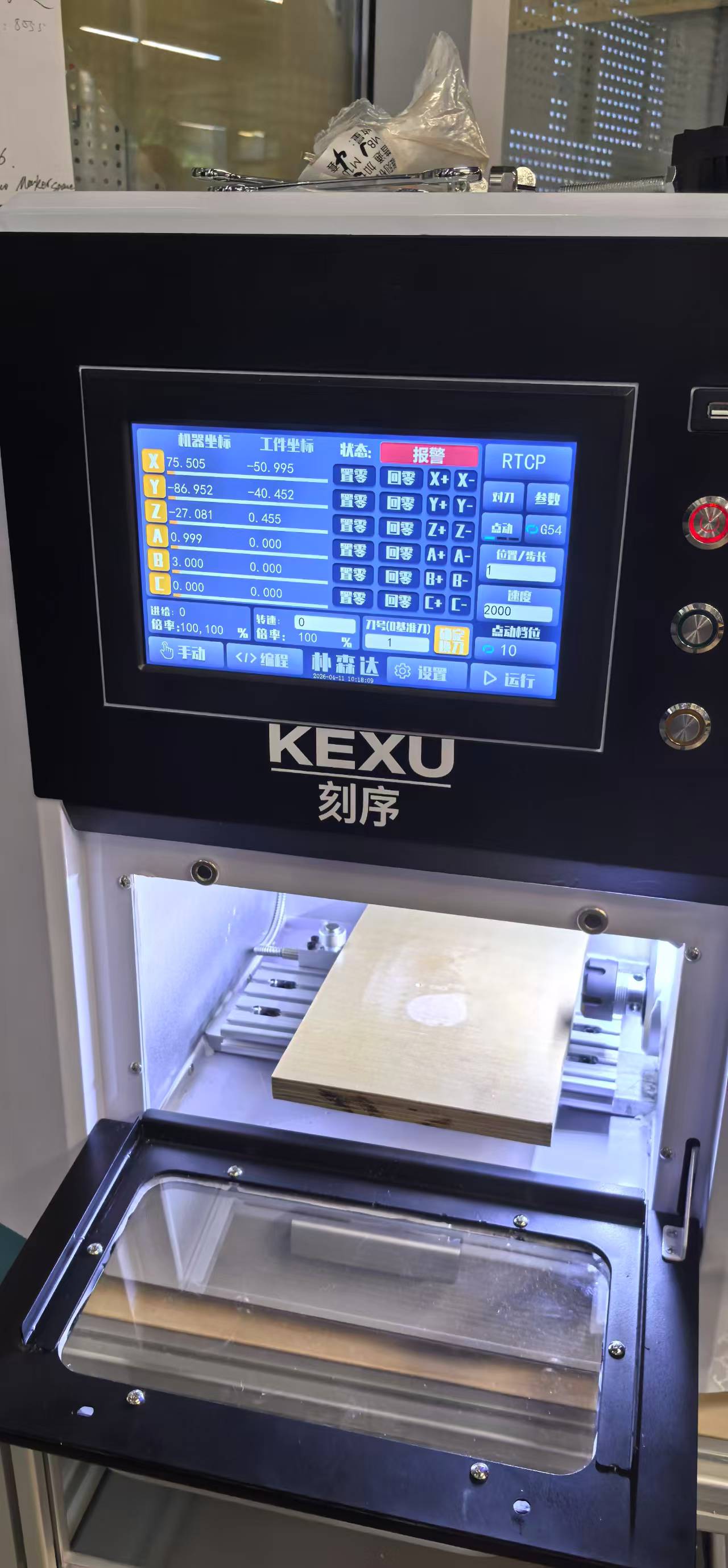
The fist thing I needed to do was to replace the toolhead.
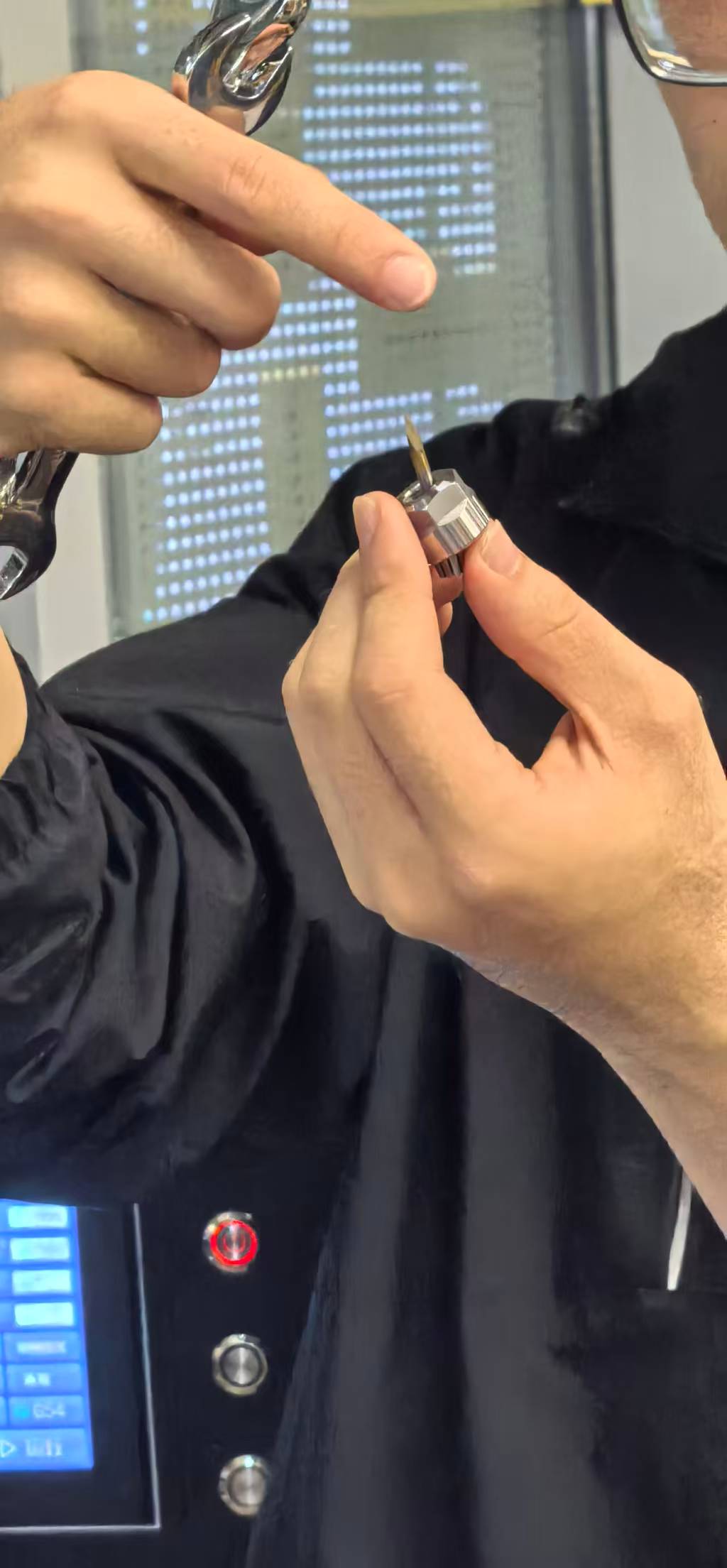
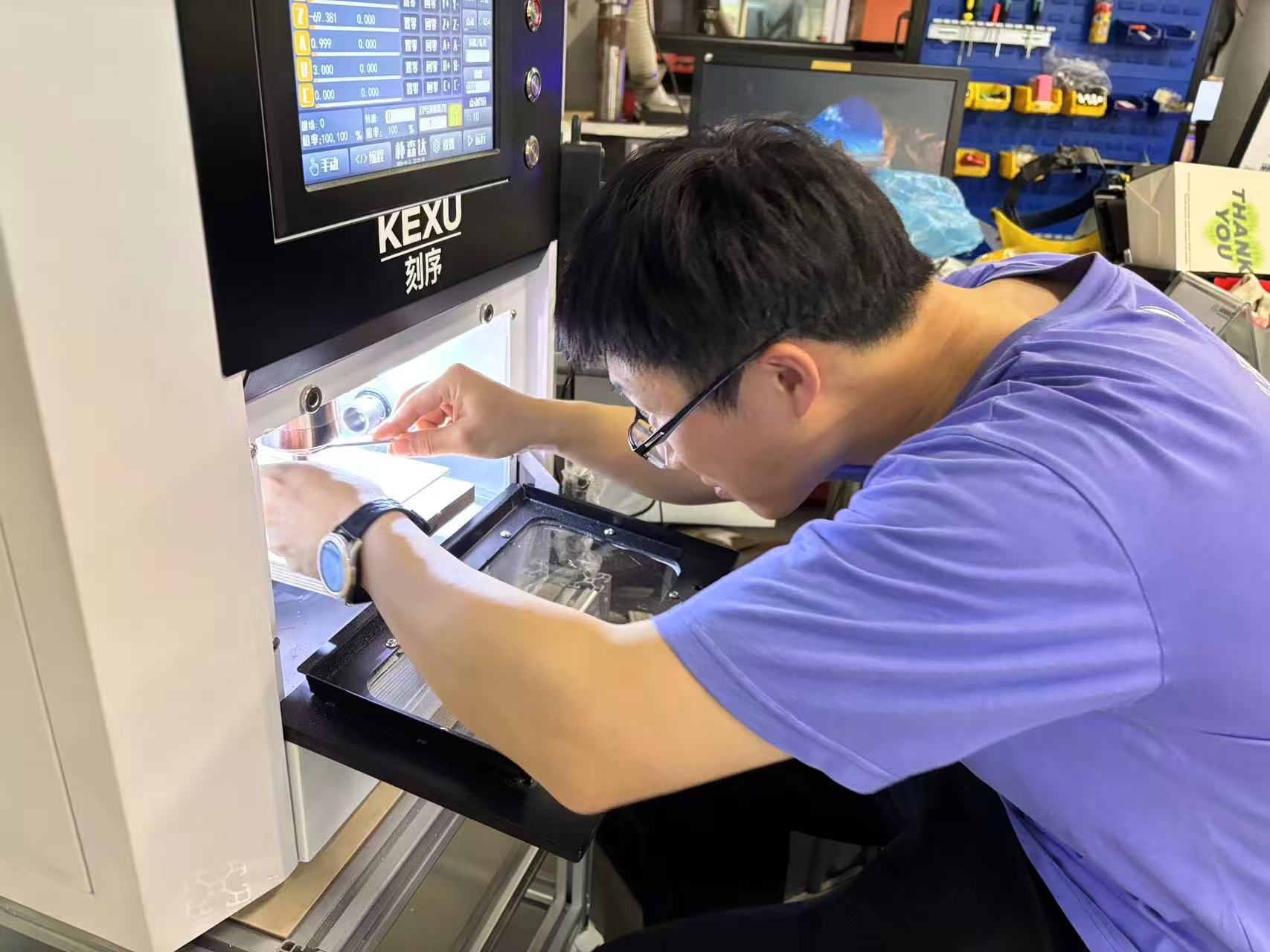
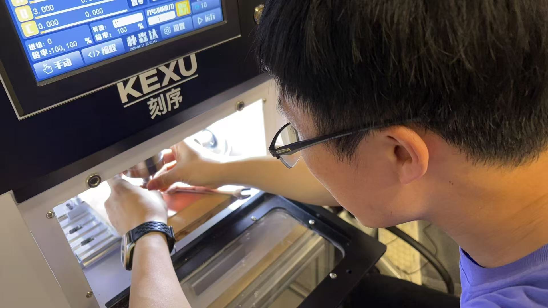
We need to use to wrenches to loosen or tighten the toolhead.
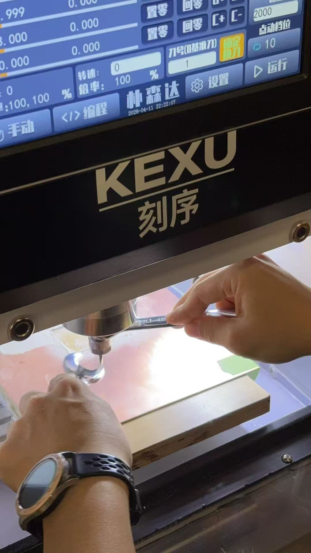
Then I mounted a board to the CNC machine.
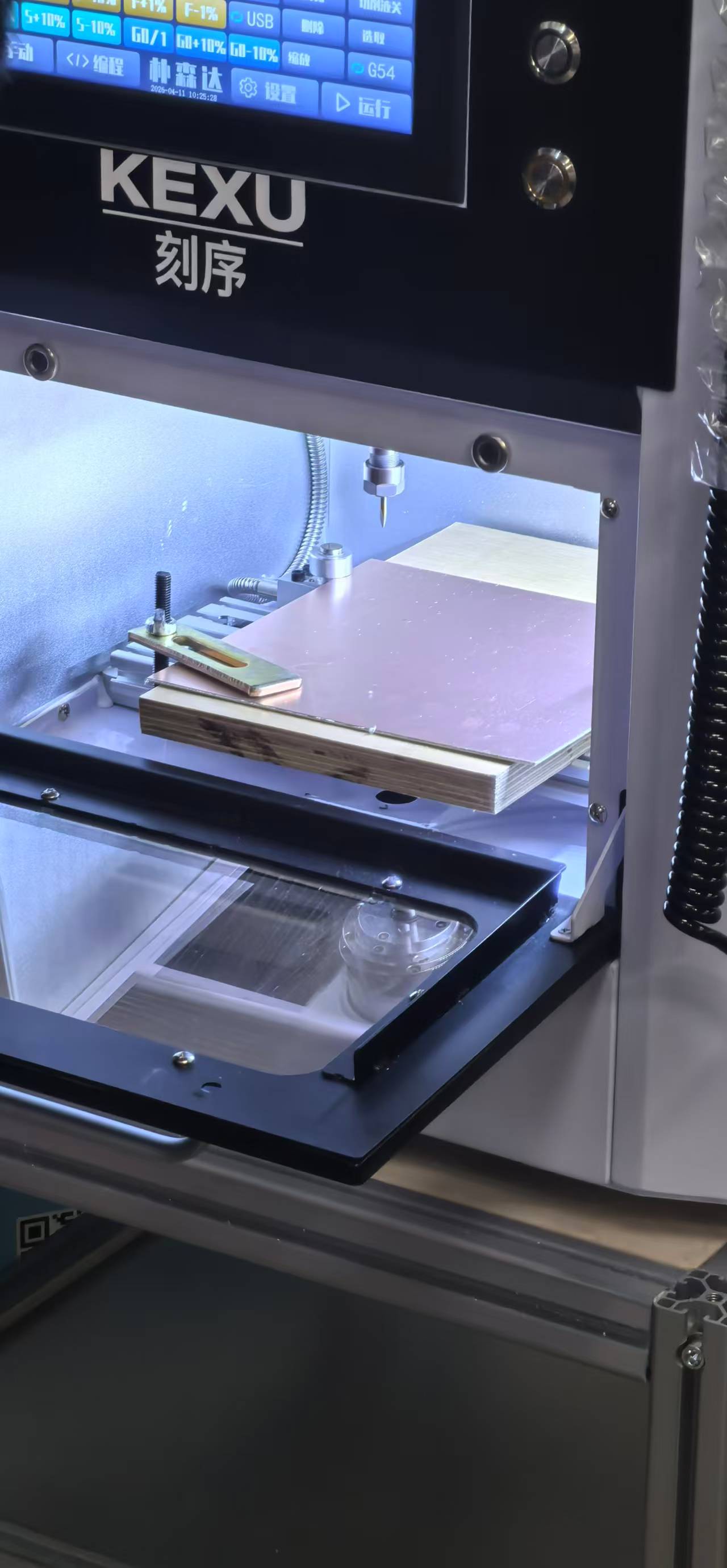
Then I manually tuned the zeroes of the CNC machine, especially the Z-zero.

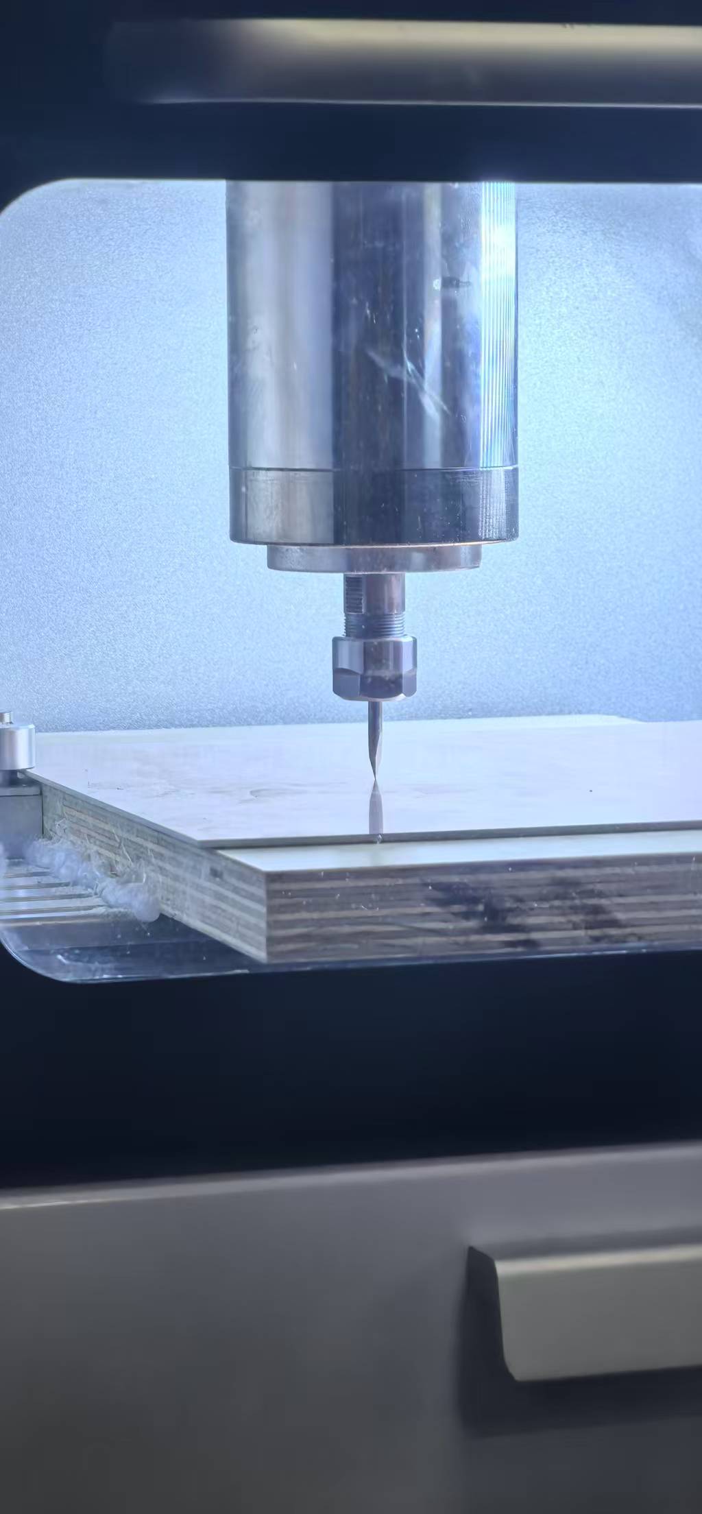
Then I started to read the gcode files from the USB disk and started the milling.
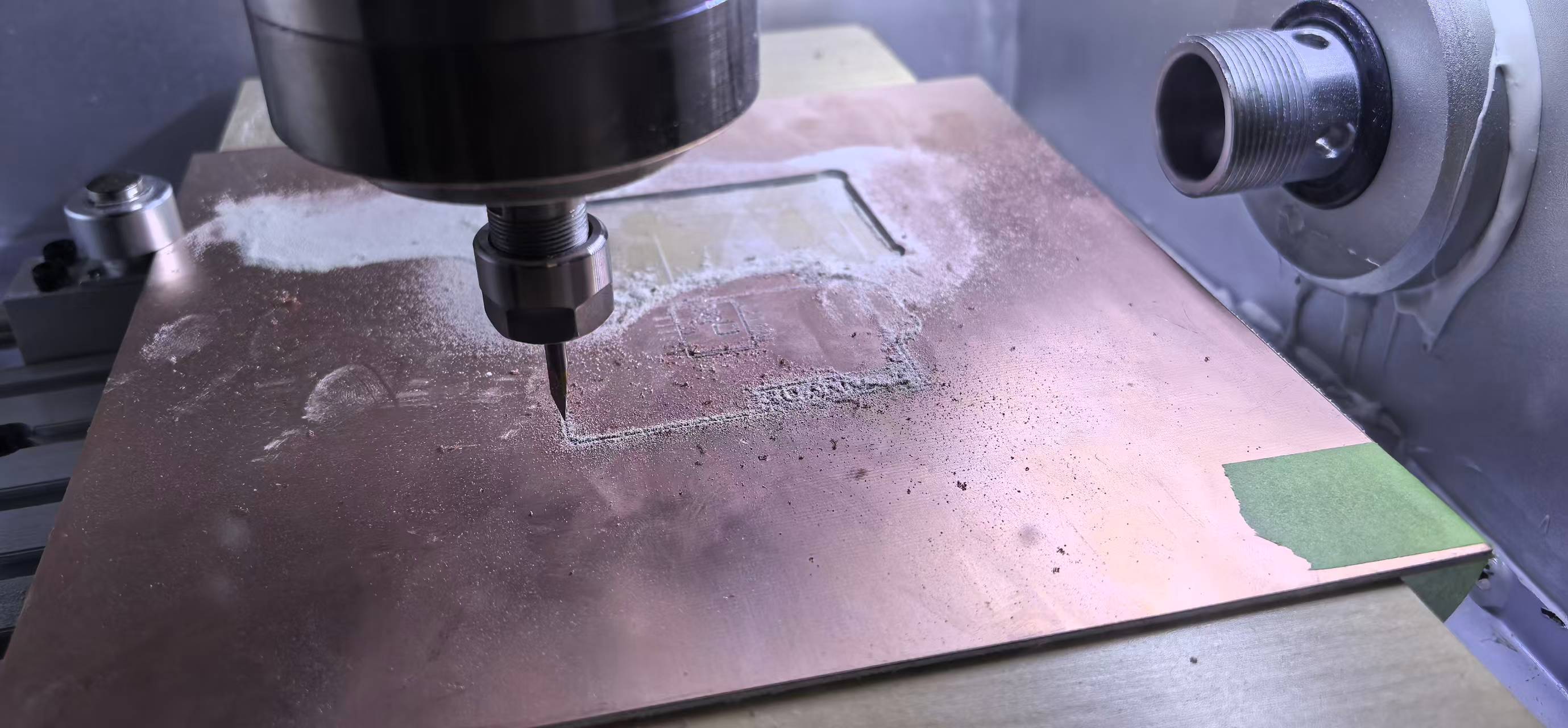
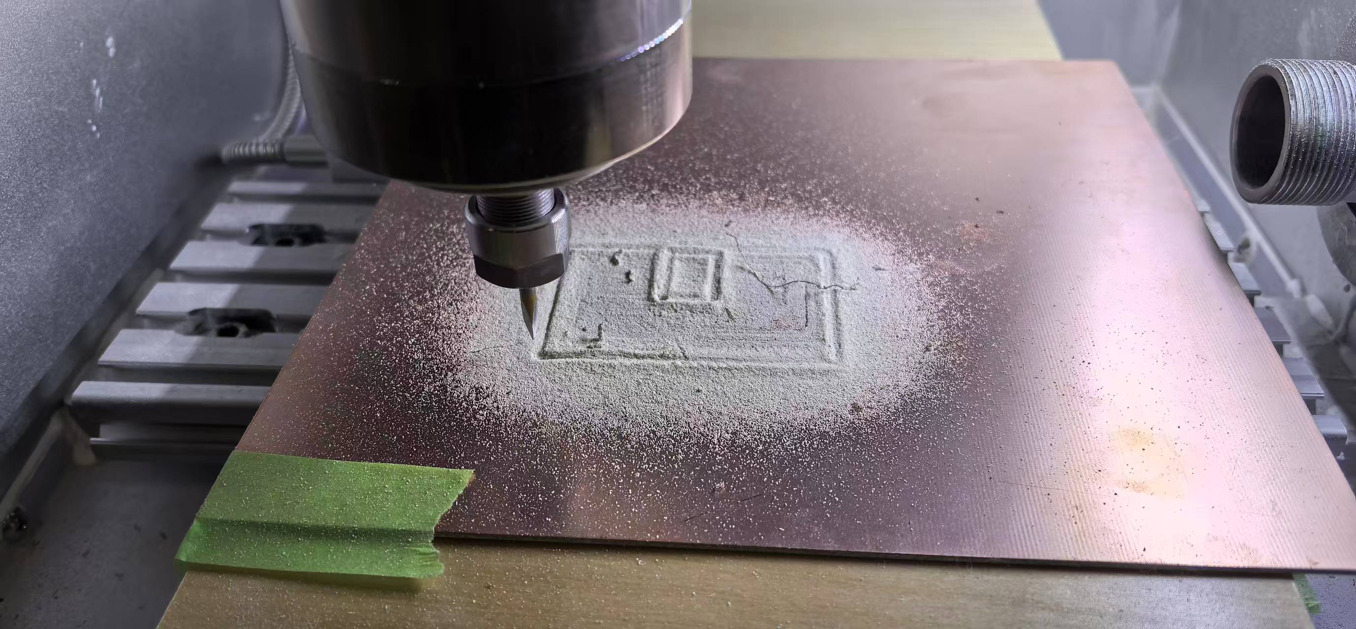
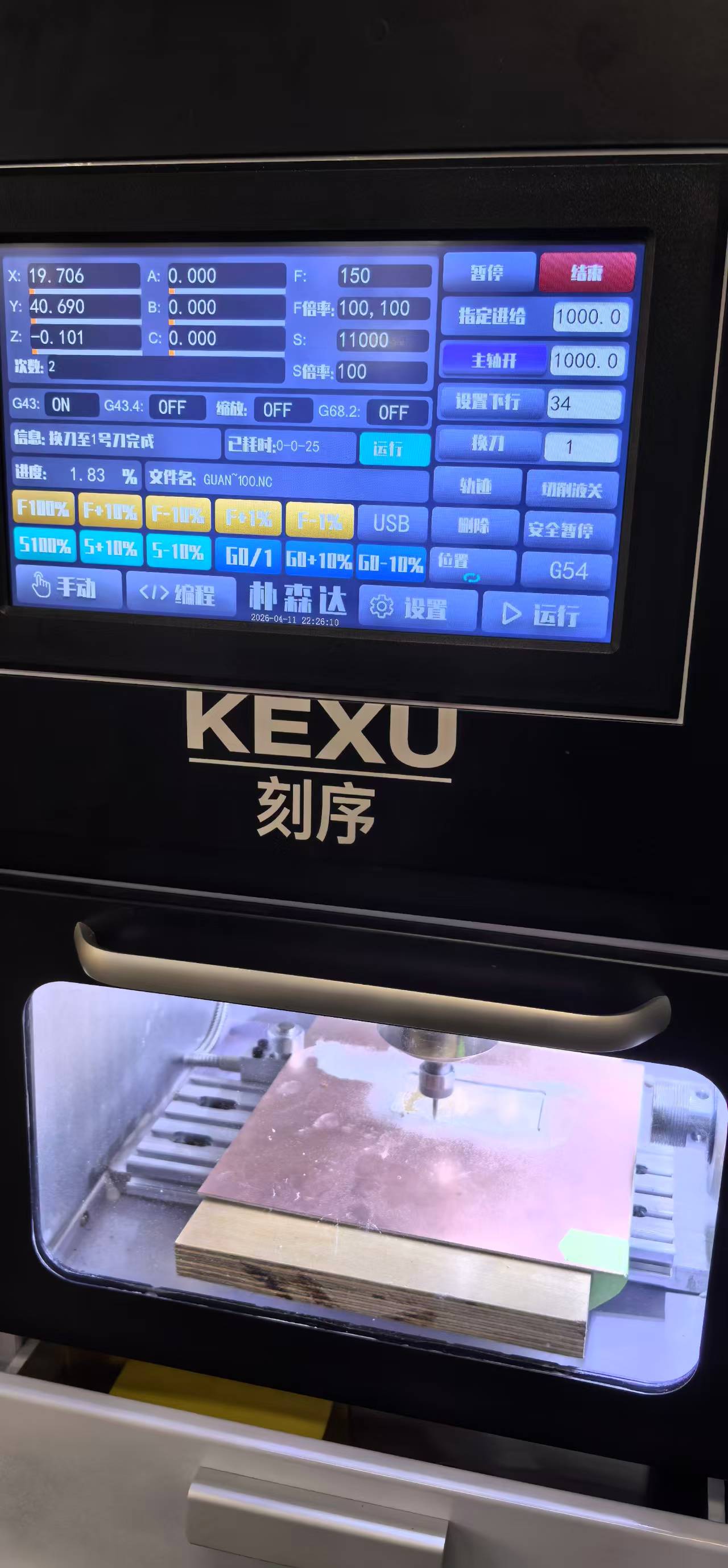
The trace and outline needed to be milled separately. Here are the short videos of the milling process.
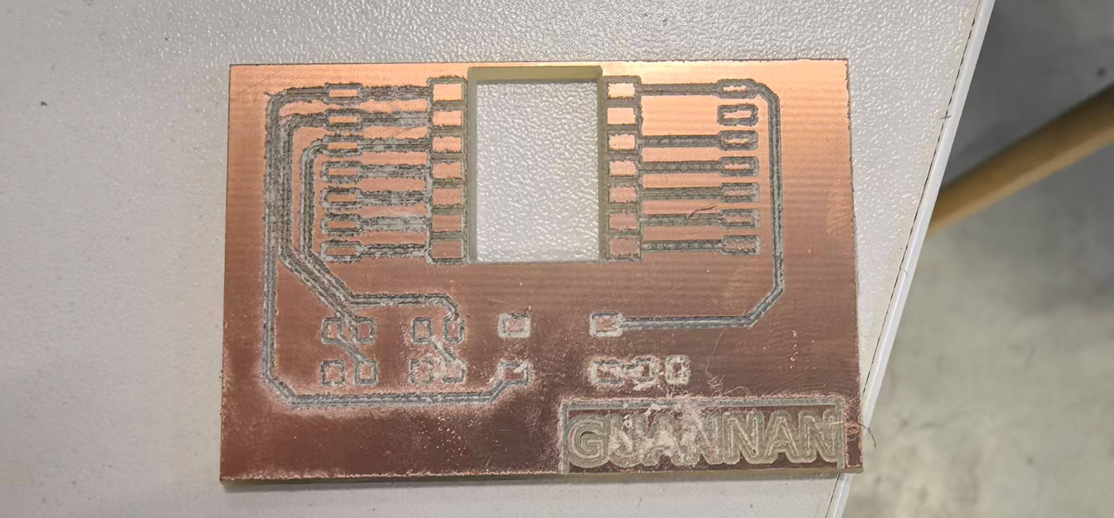
The first PCB I made was not good — traces were below the 0.8 mm minimum width rule above, so the mill broke most copper paths. I updated the LCEDA design to 0.8 mm traces / 0.8 mm clearance and re-milled successfully.
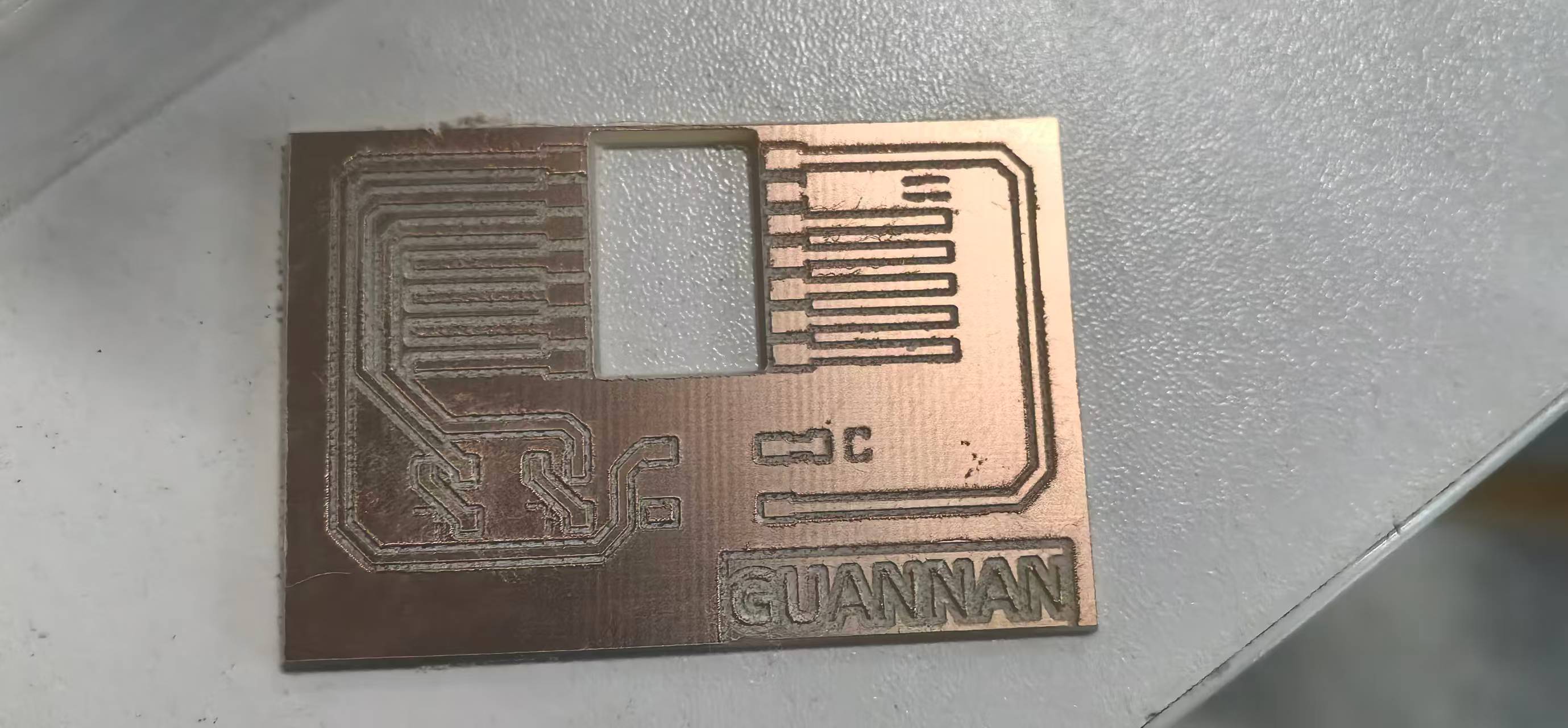
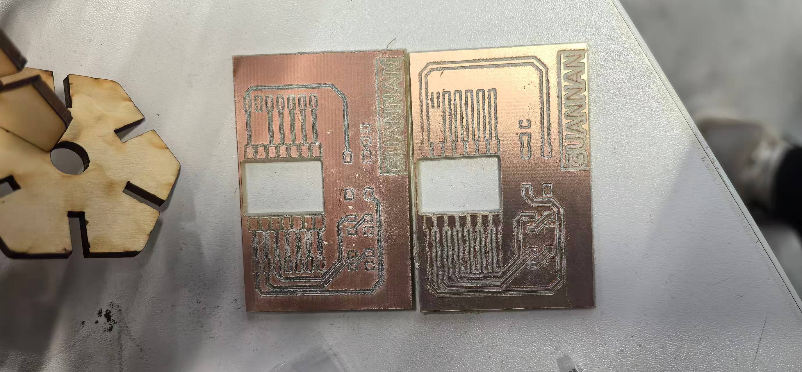
Then I soldered the components to the PCB.
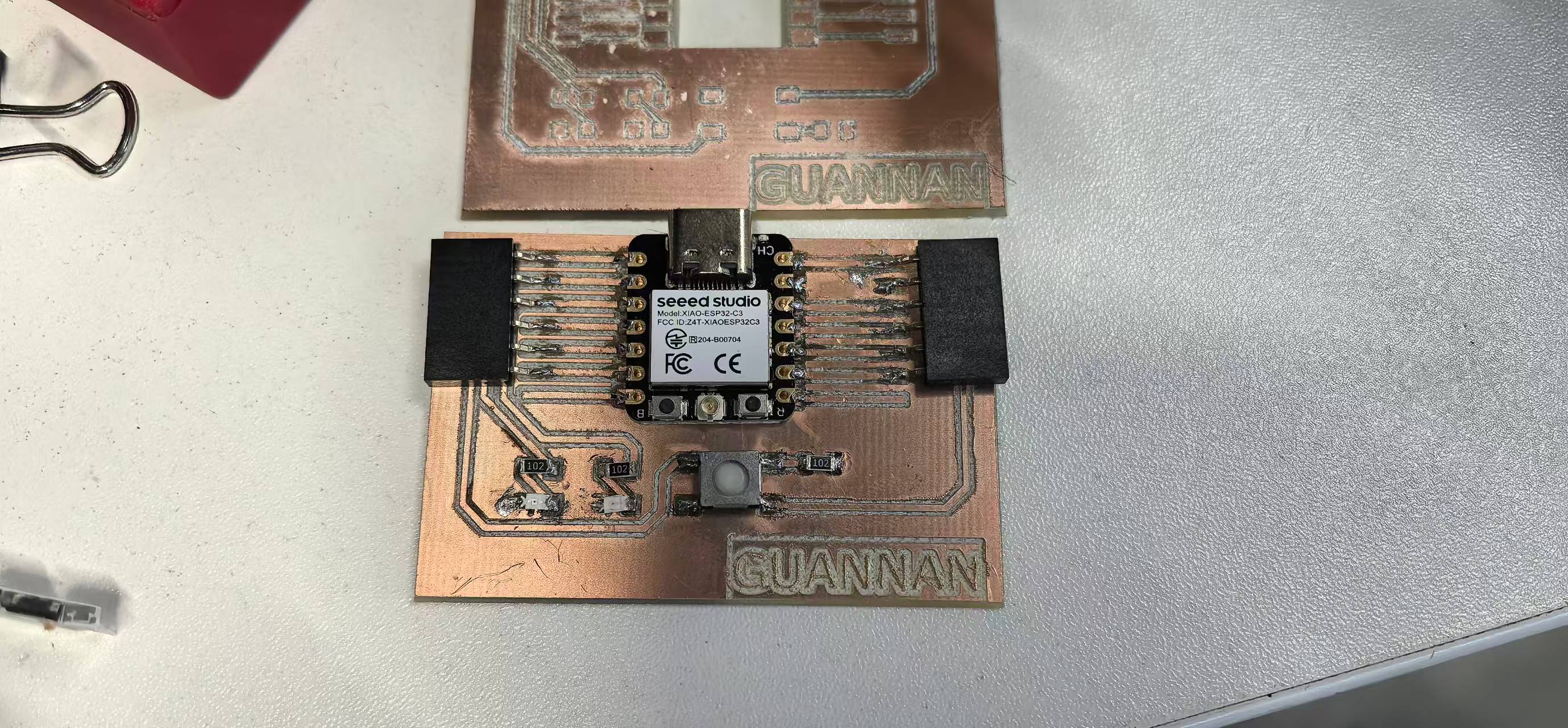
When I connected the PCB to my laptop, there was a current flow warning for the USB port. I realized there might be a short circuit.
I checked all the pins and found the issue, some of the pins were connectd to the ground directly.
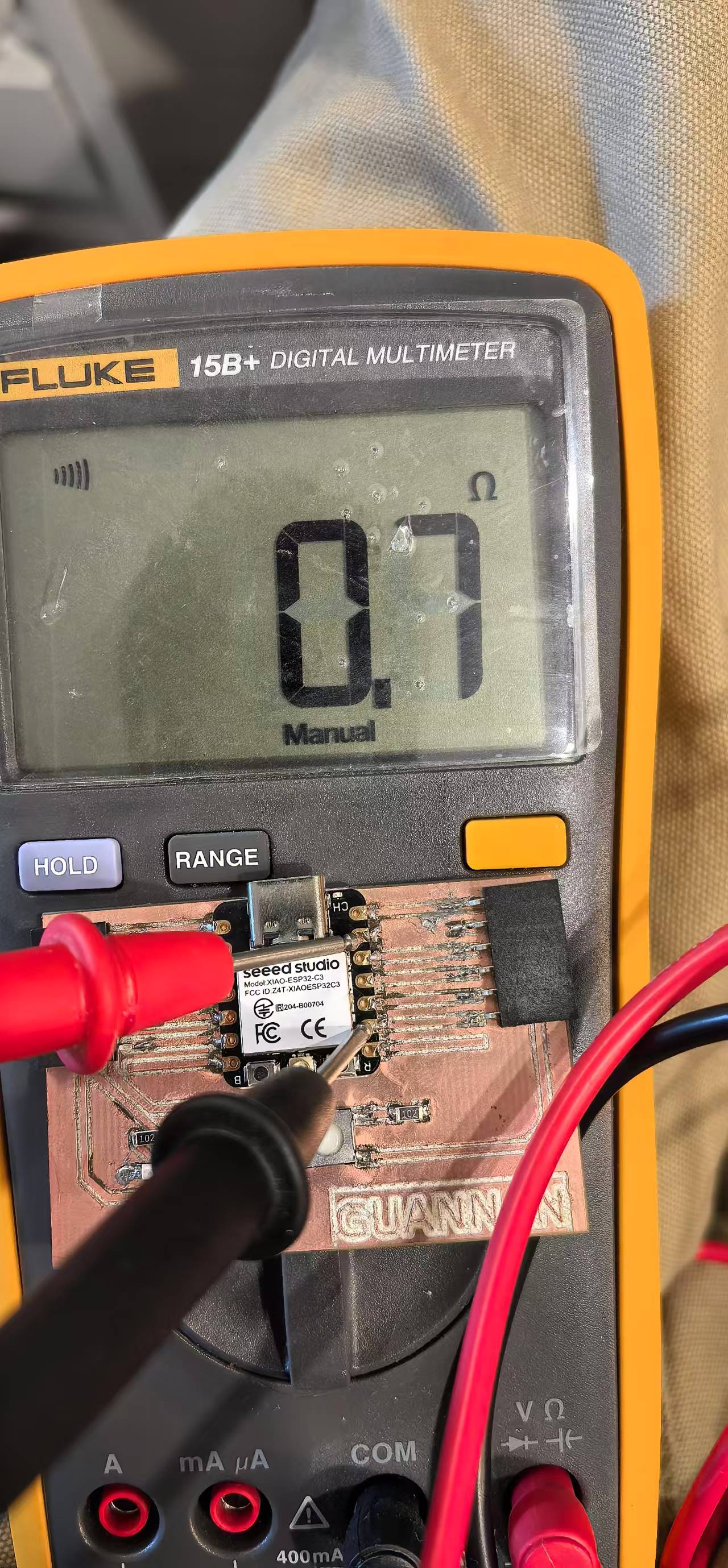
Annother issue was from the button, the metal part was on the bottom of the button which could also cause the short circuit.
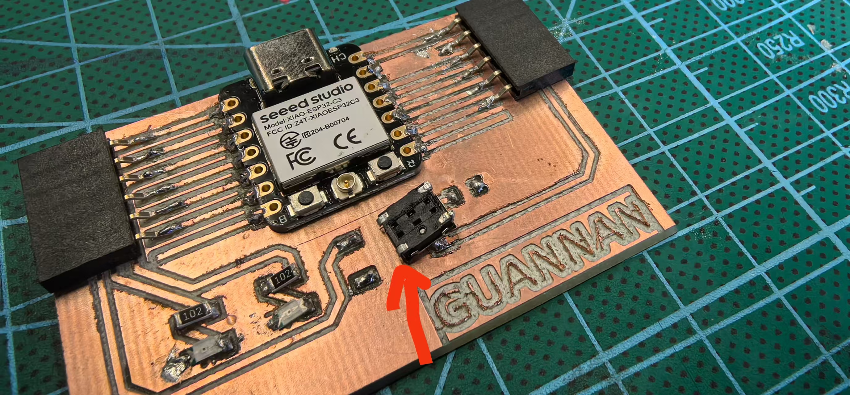
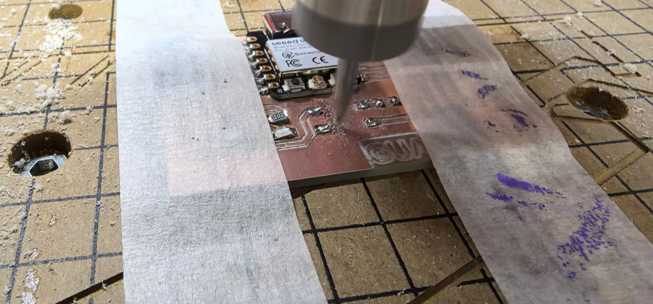
I used CNC machine to mill a square hole to remove the copper under the button.
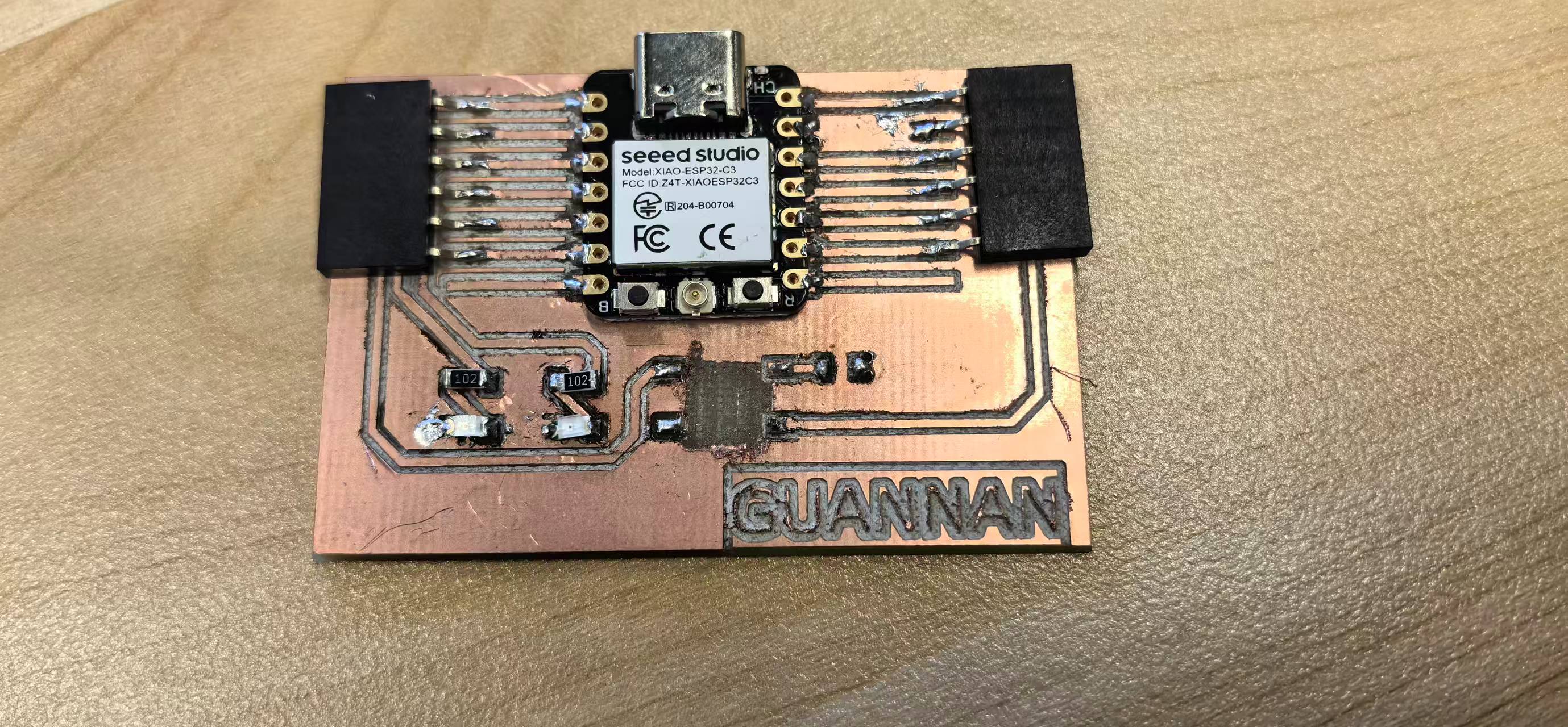
Then I upload the test code to the XIAO ESP32-C3 and the PCB worked well.
Here is the code:
const int buttonPin = D0; // button pin const int ledPin = D1; // LED pin (lights when button pressed) const int ledPin2 = D2; // LED pin for multiples of 3 int buttonState = 0; // current button state int lastButtonState = 0; // previous button state int buttonPressed = 0; // button press counter unsigned long lastDebounceTime = 0; // last debounce time unsigned long debounceDelay = 50; // debounce delay (ms) unsigned long led2StartTime = 0; // when LED2 started lighting bool led2On = false; // whether LED2 is on void setup() { pinMode(buttonPin, INPUT); // external pull-down/pull-up resistor assumed pinMode(ledPin, OUTPUT); pinMode(ledPin2, OUTPUT); } void loop() { int reading = digitalRead(buttonPin); // button debounce handling if (reading != lastButtonState) { lastDebounceTime = millis(); } if ((millis() - lastDebounceTime) > debounceDelay) { // valid button state change detected if (reading != buttonState) { buttonState = reading; // check if button is pressed (adjust HIGH/LOW based on your wiring) // For external pull-down: button connects to VCC, press = HIGH // For external pull-up: button connects to GND, press = LOW if (buttonState == HIGH) { buttonPressed++; // turn on LED while button is pressed digitalWrite(ledPin, HIGH); // if count is multiple of 3 if (buttonPressed % 3 == 0) { digitalWrite(ledPin2, HIGH); led2On = true; led2StartTime = millis(); buttonPressed = 0; // reset counter } } else { // button released, turn off the main LED digitalWrite(ledPin, LOW); } } } // turn off LED2 after 200ms (non-blocking) if (led2On && (millis() - led2StartTime) >= 200) { digitalWrite(ledPin2, LOW); led2On = false; } lastButtonState = reading; }Here is a video of the PCB working: