Laser Cutter
CAD Software
I used Laser Maker 1.5 & 2.0.
Laser Maker 2.0 needs a license (registration code) to export as DXF file, so I used v1.5 to export as DXF if needed. To use the laser cutter, I could save the files as .lcpx, so DXF is not the must.
When I installed Laser Maker 2.0 on a new laptop, I could get another 30 days trial period. It's very convenient.
Laser Cutter
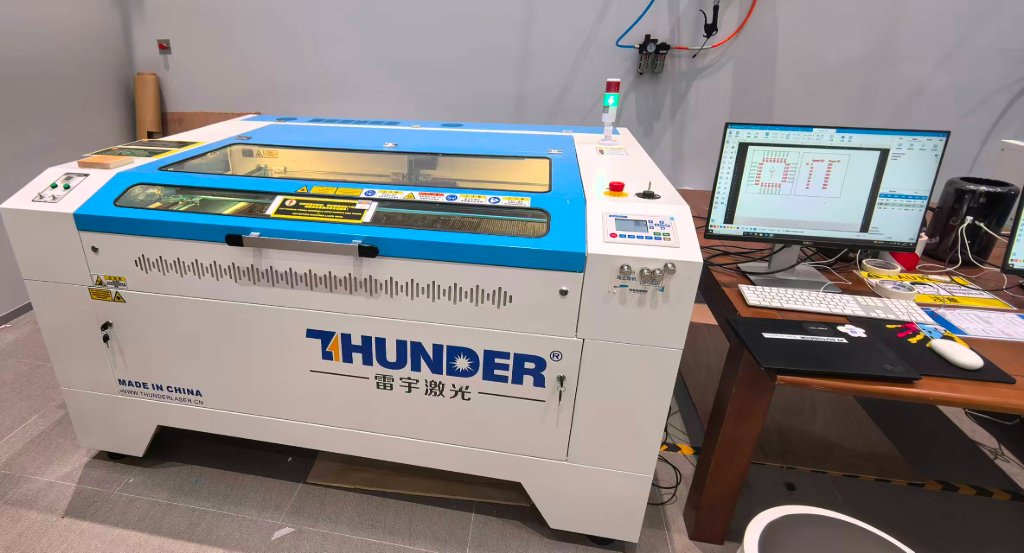
I used Thunder Laser Nova 51 with a cutting area 900 mm × 1300 mm when we (Me, Maggie and Jenny) were in Beijing.
Here is the picture of the laser cutter:
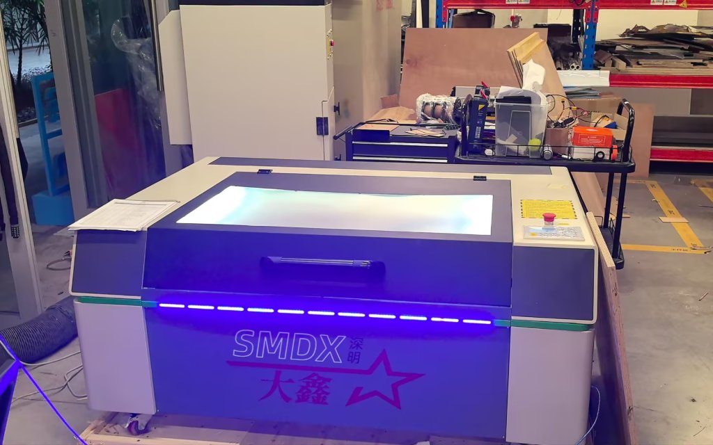
We used a different laser cutter in Chaihuo.
In the group work, we tested the tolerance.
Here is the link of Our group assignment
The result was:
Positive features (material to be preserved): Actual width = Design width - 0.1mm → Design compensation: +0.1mm
Negative features (slots/grooves to be cut): Actual width = Design width + 0.1mm → Design compensation: -0.1mm
The safety precautions of the laser cutter are:
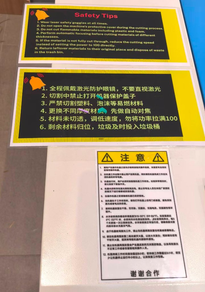
We should always wear the safety goggles when we are using the laser cutter.
At the beginning, while we were observing the laser cutter machine, we were not wearing the safety goggles, we all got warned by the lab technician.
Another important thing for using laser cutter is to notice the thickness of the material. Every time, an auto-focus operation will be suggested to be performed.
There is a camera on the laser cutter, we can align the patterns with the camera view easily, but there might always be a shift, so to let the head go through the path first is highly recommended.
The laser cutter in Chaihuo is different and the software is different, but the usage is similar.
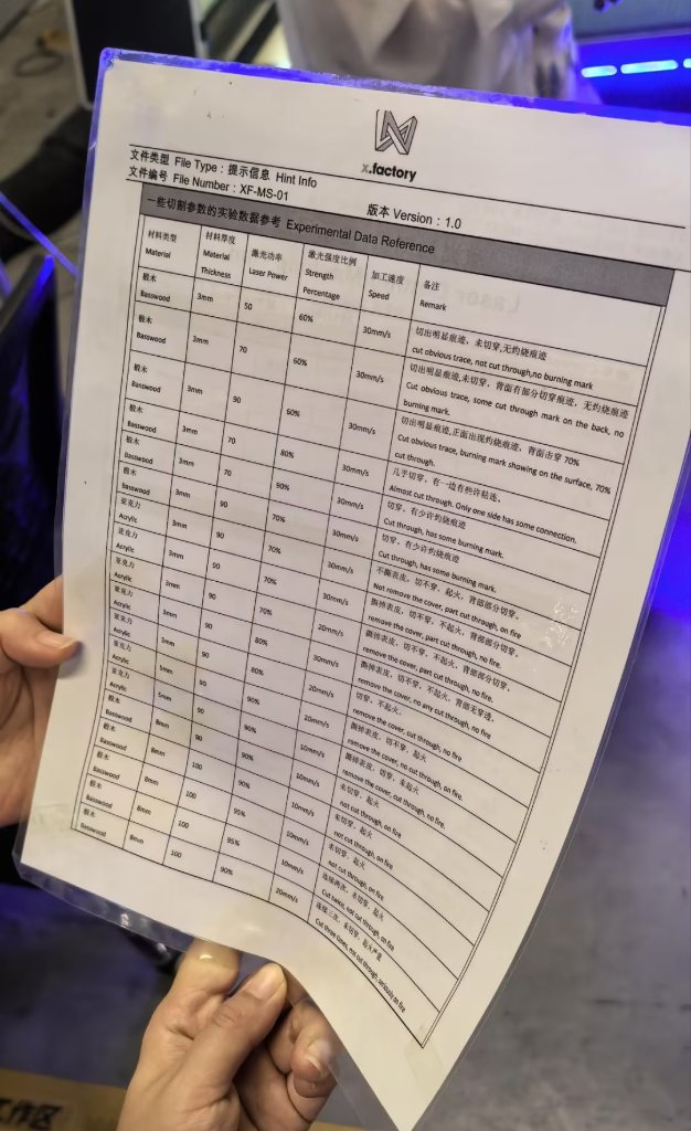
The parameter for cutting:
Laser Cutting Project - Puzzle
To use the laser cutter in Chaihuo, I made a new personal project after the training from Chaihuo instructor.
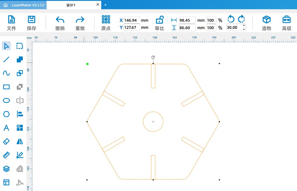
I used Laser Maker 2.0 to design the project. A simple piece was schetched.
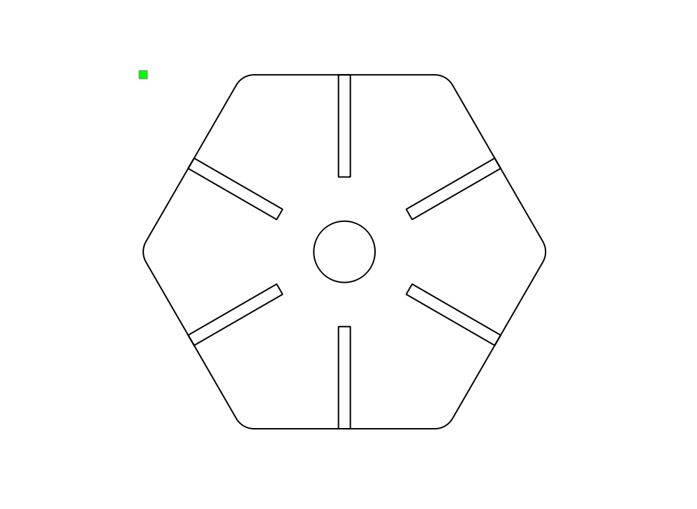
I realized the size was not correct, so I modified the size to make it smaller and make the gap shotter.
The thickness the board was 3mm, by considering the tolerance, I made the gap width as 2.9mm.
Then I exported the file as a DXF file.
The file was opened on the laptop which was connected to the laser cutter.
The cooler for laser generator and the air purifier needed to be turned on manually.
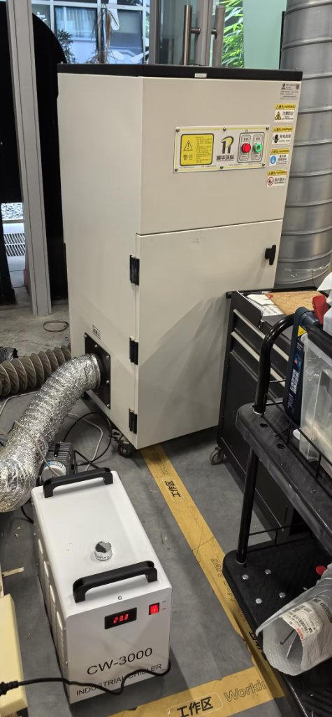
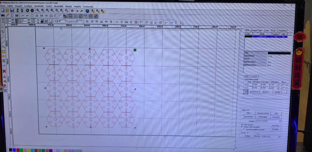
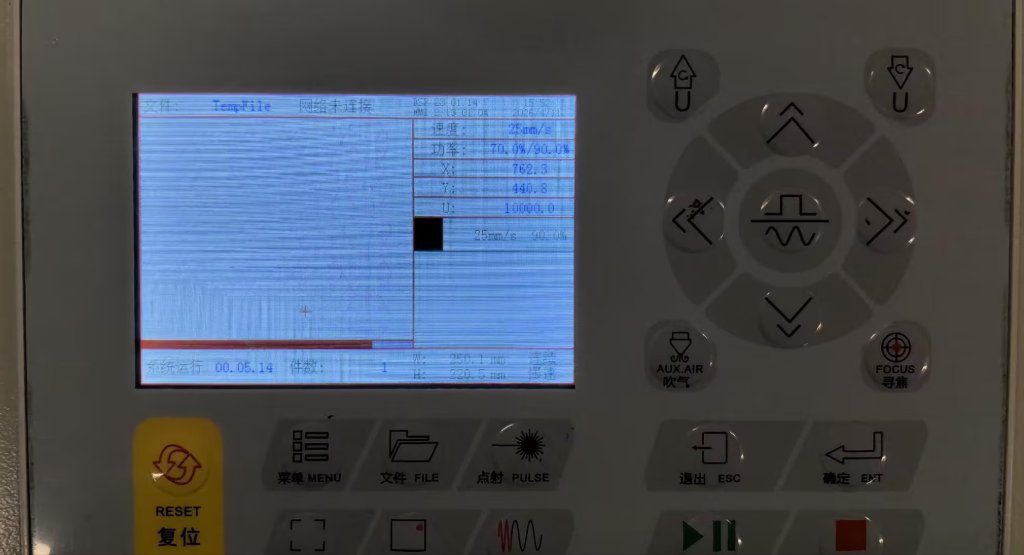
Then I sent the task to the laser cutter. It's not transparent, but I could use the panel to see the progress of the cutting.
The air purifier was not working well, so I had to open the door when it was cutting. The smell and fog were quite obvious.
After it's done, I could took all the pieces out.
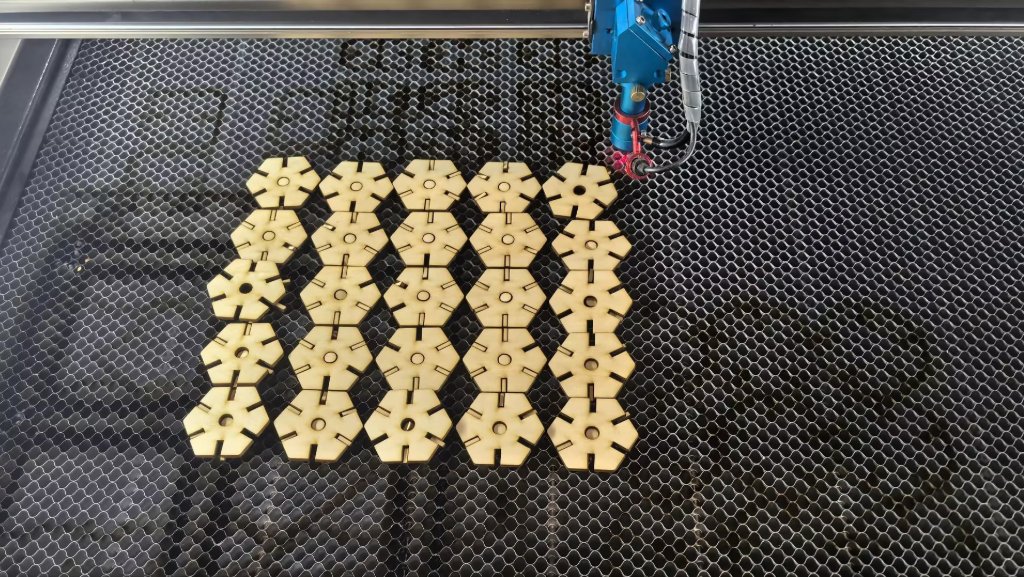
The small pieces are like puzzles, I could assemble them to different shapes.
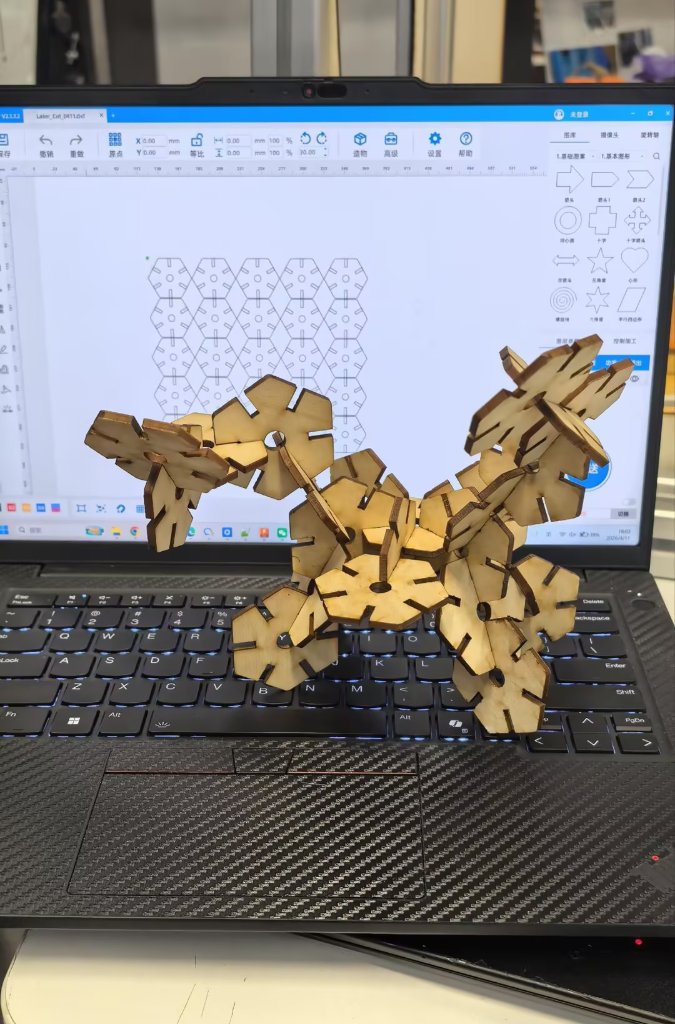
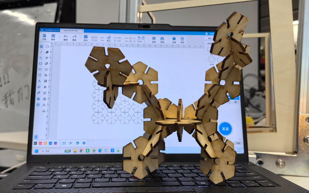
Here is the DXF file: Laser_cutter_0411.dxf
Laser Cutting Project - Horse
I used Doubao AI to generate a picture of horse (the Chinese traditional paper cutting style), then I used Photoshop to edit the image. Then I imported the image into Laser Maker.

The AI generated picture of horse.

The edited picture of horse.
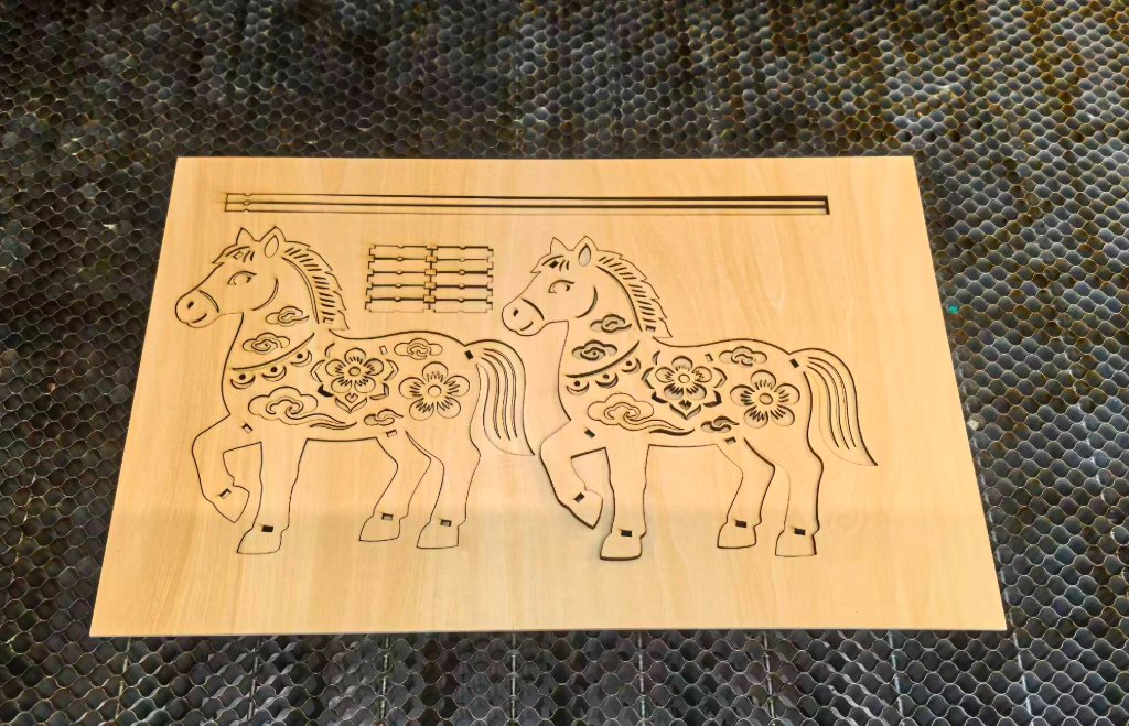
I used Thunder Laser Nova 51 to cut the horse. I used the 3mm-thickness plywood to cut it.
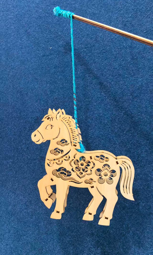
The assembly of the horse.
The assembly of the horse.
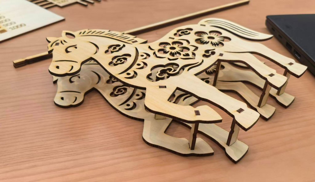
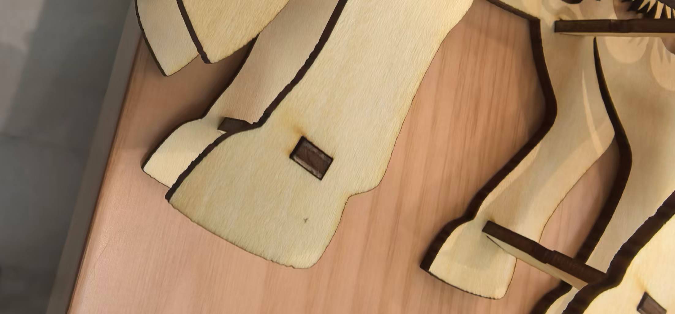
The assembly of the horse. When I tried to assembling the horse, I found that even I considered the tolerance, some parts were still not fit perfectly, some were too tight, while some were loose. I also realized that the wood board was not exactly 3mm thick.
The assembly of the horse. After I finished assembly, I found the horse was strange as it looked like to be with 8 legs.
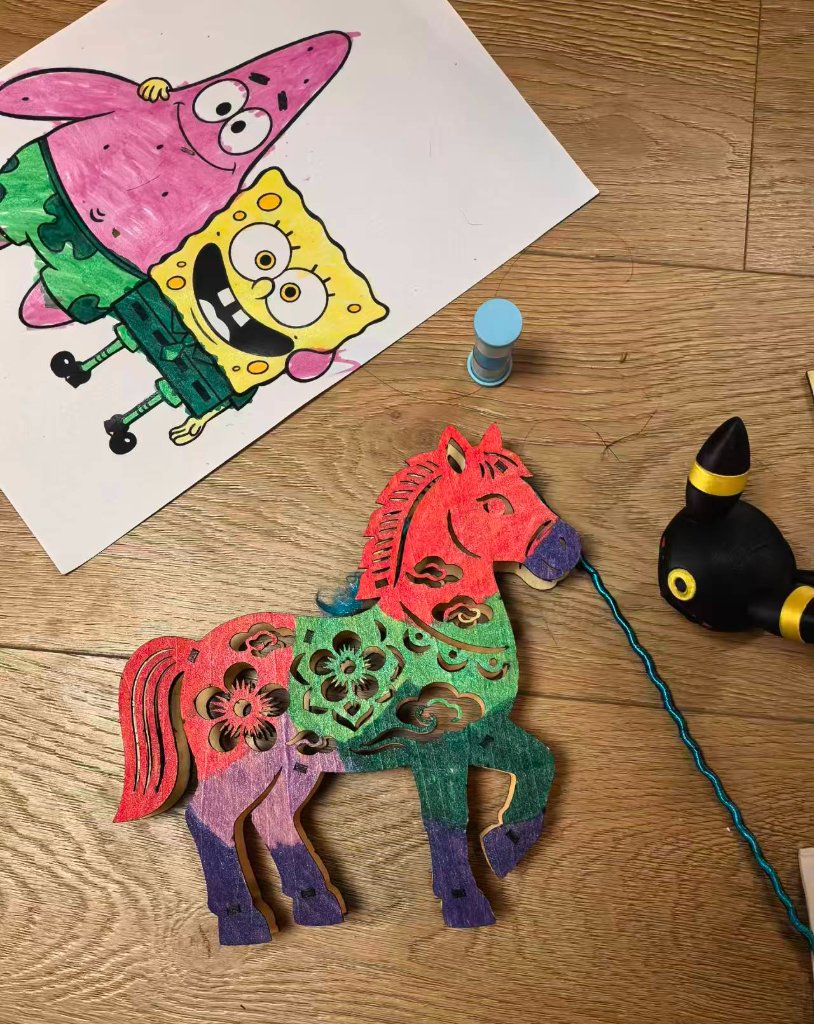
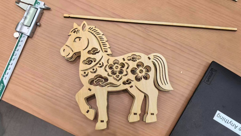
The assembly of the horse. My daughter liked it very much and she helped to color the horse.
The original file for Laser Cutter is here: horse_laser.dxf
Parametric Design with Fusion 360
After discusion with my instructor, I realized that I did not make a correct parametric design for Laser Cutting. So I used Fusion 360 to redesign the assignment.
Here are the steps of the parametric design:
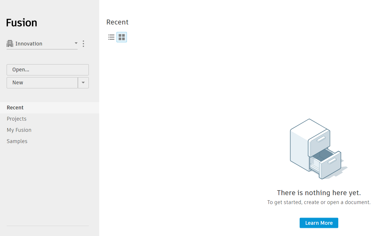
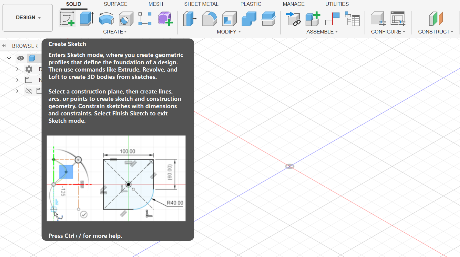
Open the software and create a new project.
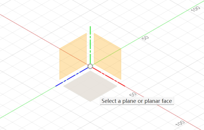
Then I created a new sketch on the plane.
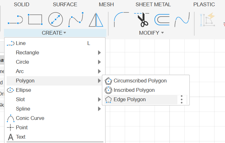
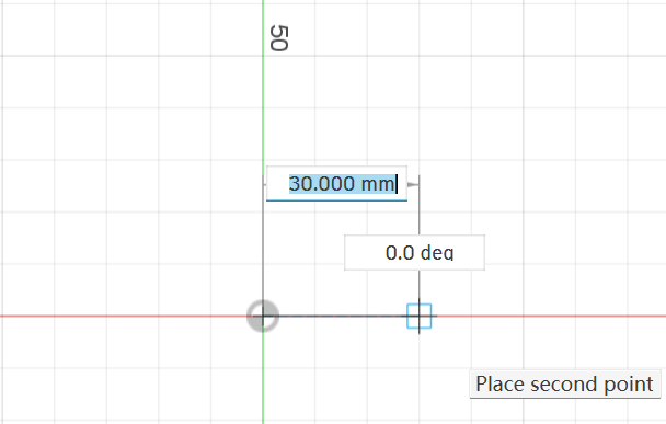
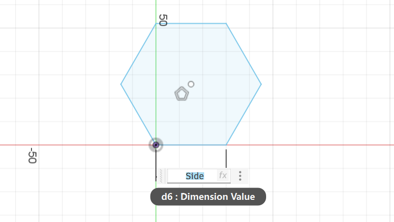
Then I used the polygon tool to create a polygon with 6 sides.
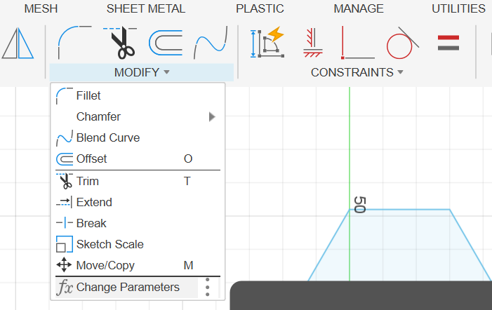
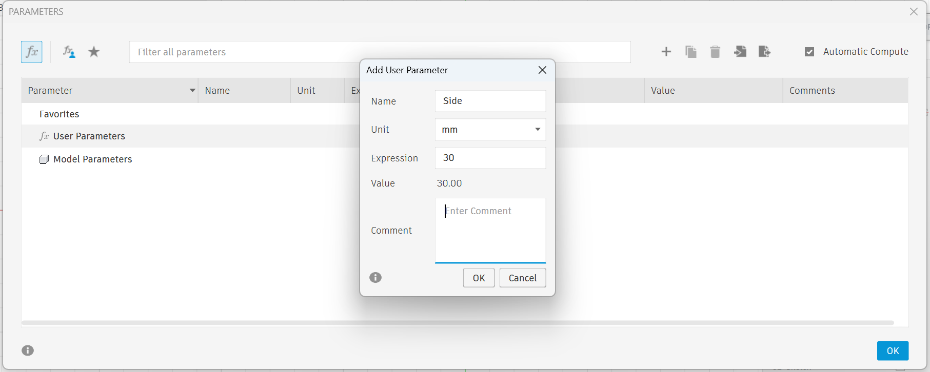
I forgot to create the parameters first. So I went to "Modify" -> "Change Parameters" to create the parameters.
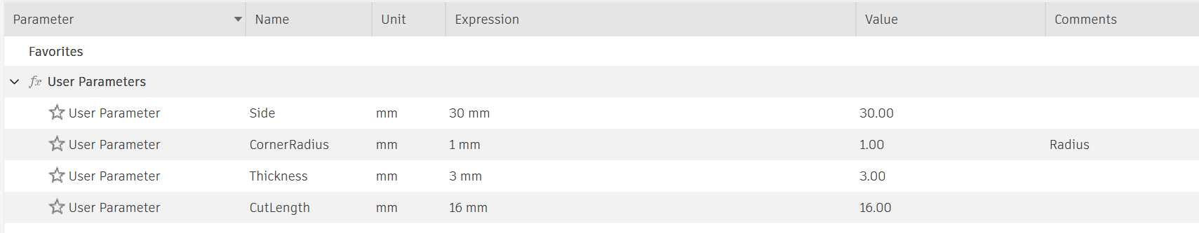
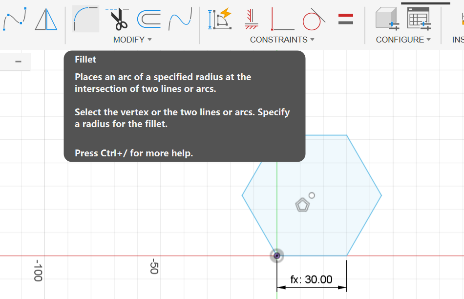
Then I apply the "Side" to the polygon sides.
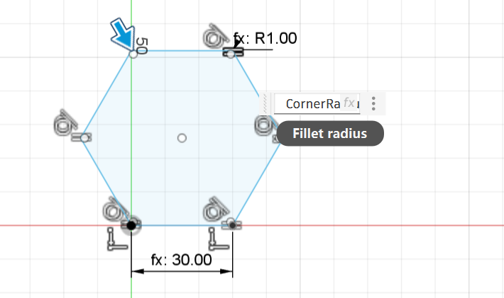
Then I used the "Fillet" tool to fillet all the edges.
I set the radius as "CornerRadius" which was a parameter I created before.
I created a rectangle on the side, made the length as "Cutlenth" and the width as "Thickness+0.1" to consider the tolerance.
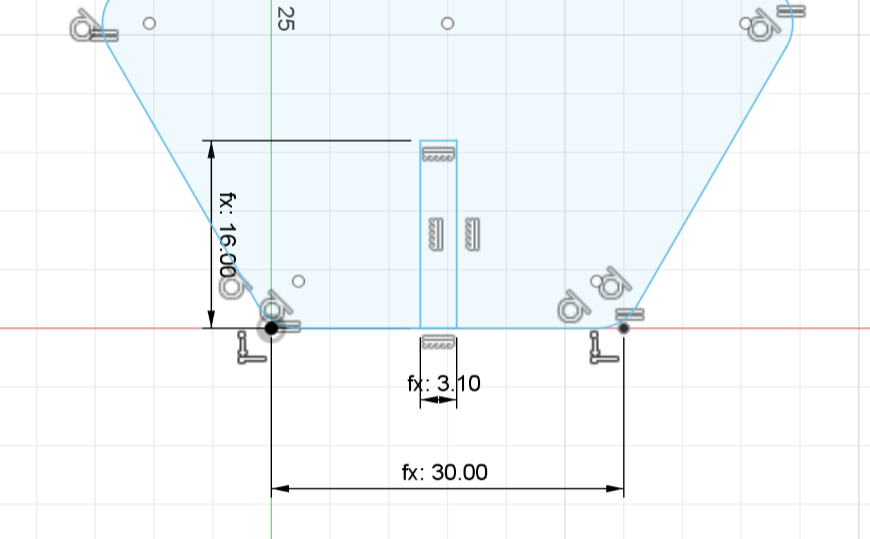
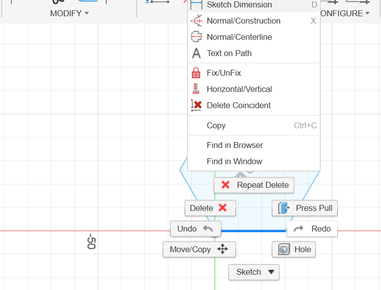
Then I added a constraint to the rectangle to be the same midpoint as the polygon side.
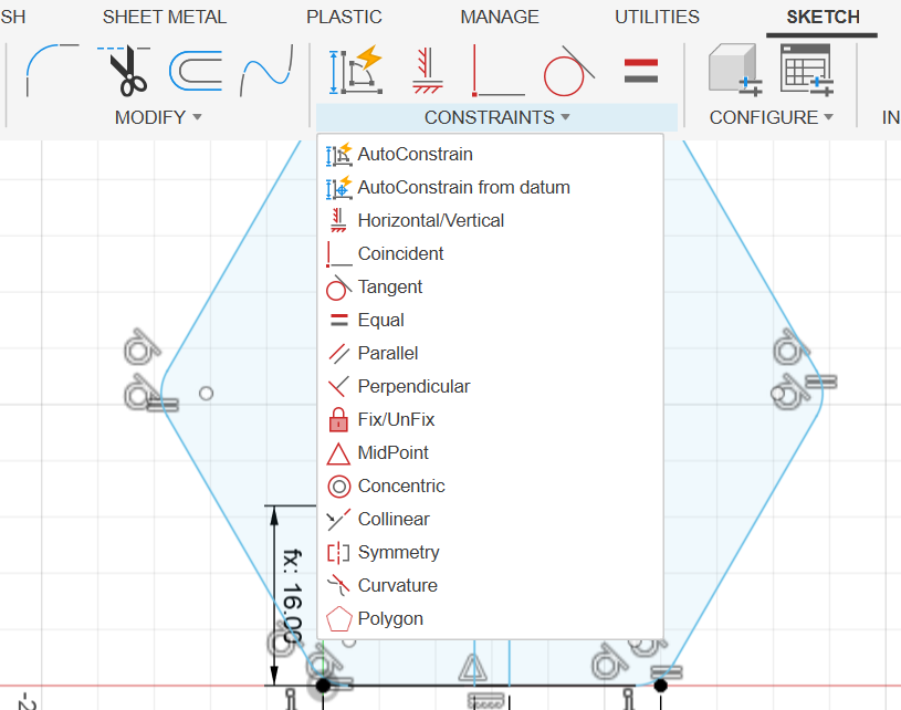
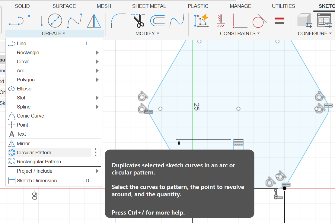
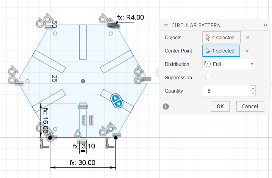
Then I used the "Circular Pattern" tool to pattern the rectangle to the polygon sides.
I put the configuration table on the right side of the screen.
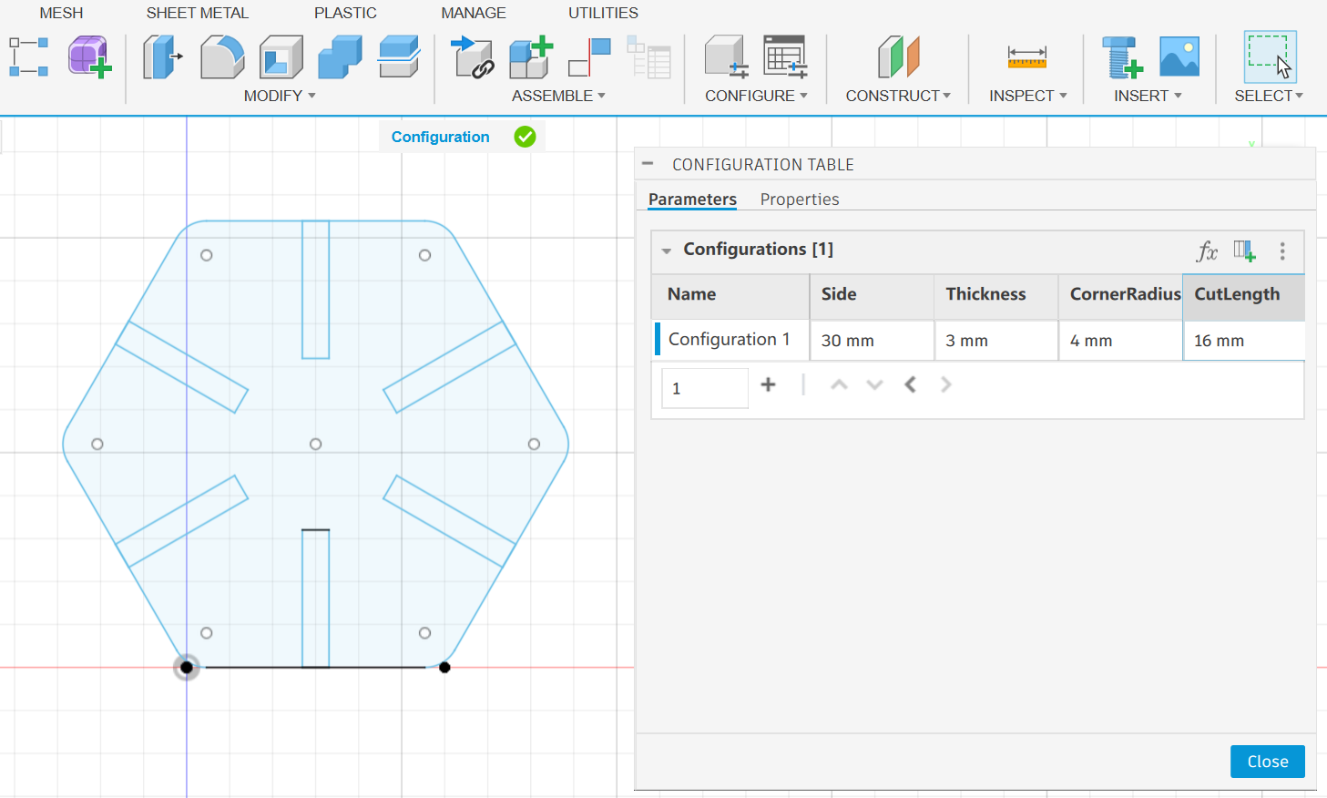
Now the design is a parametric design, I could change the parameters to get different designs.
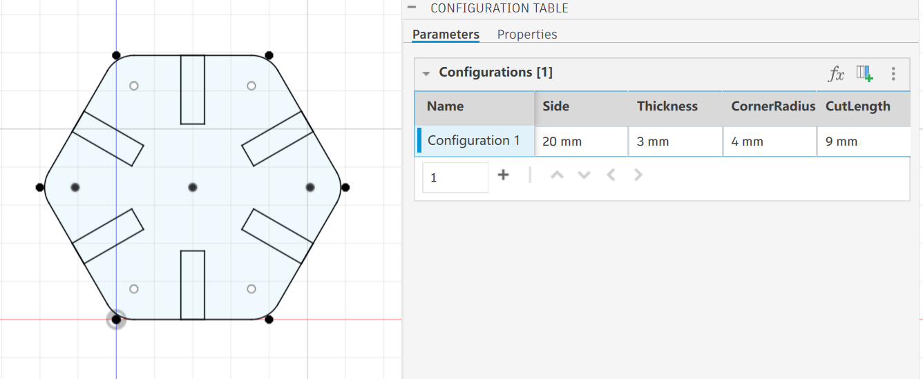
I could export the design as a DXF file.
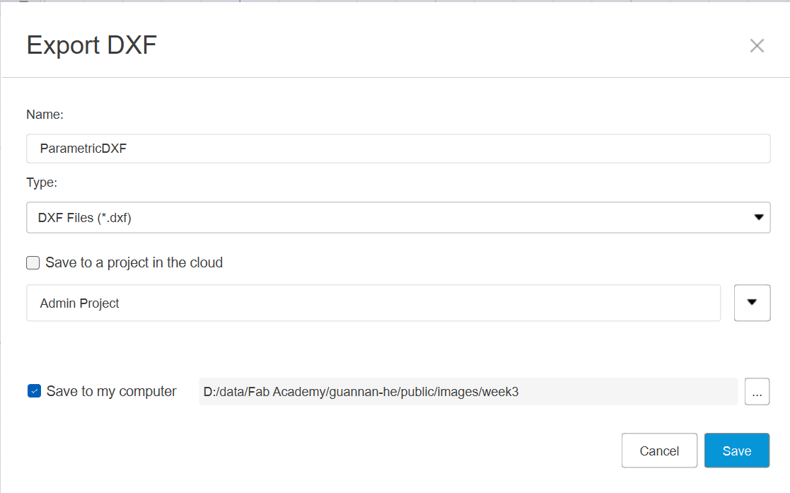
Here is the DXF file: ParametricDXF.dxf
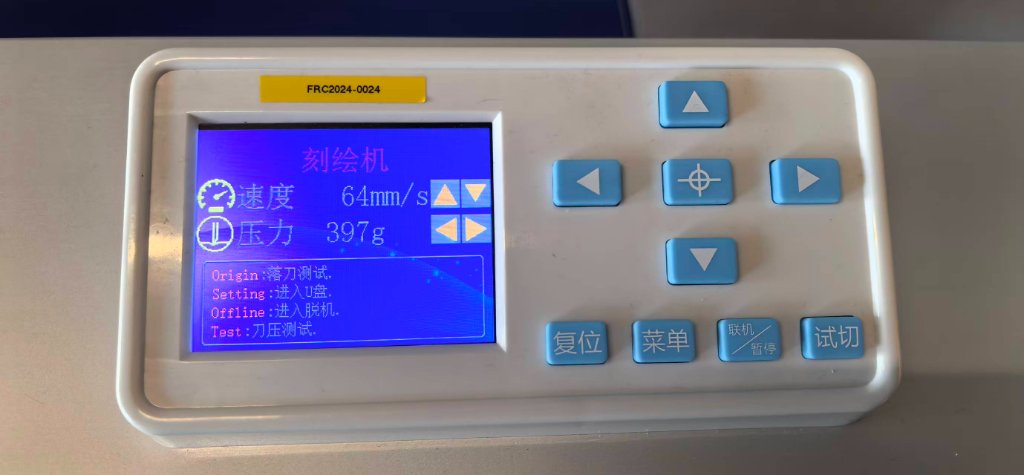
Vinal Cutter
We have a vinyl cutter in the lab.
Here it is:
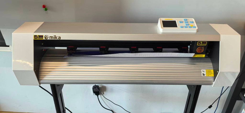
The software I used is AIDCut, it's installed on a Windows PC.
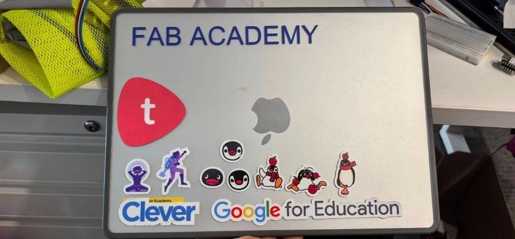
I just tried to cut the simple text "FAB ACADEMY", it could edited directly in the AIDCut.
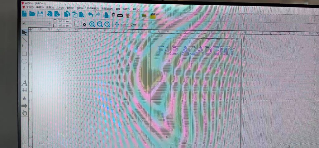
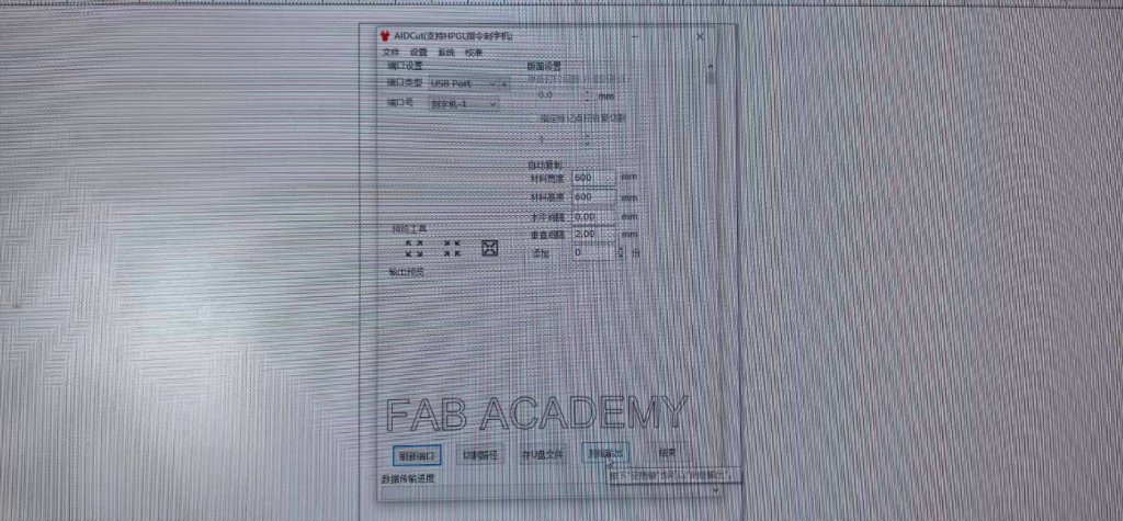
After I edited the text, it could sent to the vinyl cutter to cut.
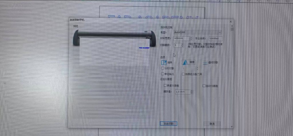
Here is a video of the vinyl cutter cutting the text "FAB ACADEMY":
After I cut the sticky paper, I put it on my personal laptop.