System Integration
Week 16 is about bringing separate subsystems together into one working product. For my final project — Voice Keeper (an audio photo album) — I planned how mechanical, electronic, and software parts fit inside one enclosure, documented the layout with sketches and CAD, and started packaging so the device looks like a finished object rather than a breadboard demo. This page maps directly to the Fab Academy checklist below.
See also:
Voice Keeper — System Integration on my final project page.
Checklist
- ✓ Made a plan for system integration for your final project
- ✓ Documented your plan with CAD and/or sketches for system integration
- ✓ Implemented methods of packaging
- ✓ Designed your final project to look like a finished product
- ✓ Documented system integration of your final project
- ✓ Linked to your system integration documentation from your final project page
Project Overview — Voice Keeper
Voice Keeper is a physical audio playback station for printed photographs. A user places a photo on an inclined tray; four colour sensors read a quinary-encoded strip on the photo edge; the MCU looks up an ID and plays the matching MP3 through a speaker. A keypad and play button provide manual fallback. Full concept and electronics architecture are on my
final project page.
Subsystems to integrate this week:
- Mechanical: base enclosure, photo tray (box), sensor window cut-outs, speaker cut-outs, touch sensor cut-outs
- Sensing: 4× TCS34725 via TCA9548A I2C multiplexer (tested in Week 11, but TCA9548A needs more testing)
- Audio output: DFPlayer Mini + speaker (UART, Week 11)
- User input: touch sensor
- Control: SEEED XIAO ESP32-C3 (Week 8 board evolution)
- Power: Li-ion cell, USB-C charge module, 5 V boost for DFPlayer and logic
- Status feedback: discrete green/red LED or small RGB indicator (optional WS2812 from Week 10 experience)
1. System Integration Plan
Before cutting or printing parts I wrote an integration plan that lists what goes where, in what order it is assembled, and what could fail at the interface. The goal is one closed box: no loose jumper wires visible, all connectors reachable for repair (ideally), and enough light at the sensor windows for colour reading without adding LED illumination (per final-project spec).
Integration sequence (bottom → top):
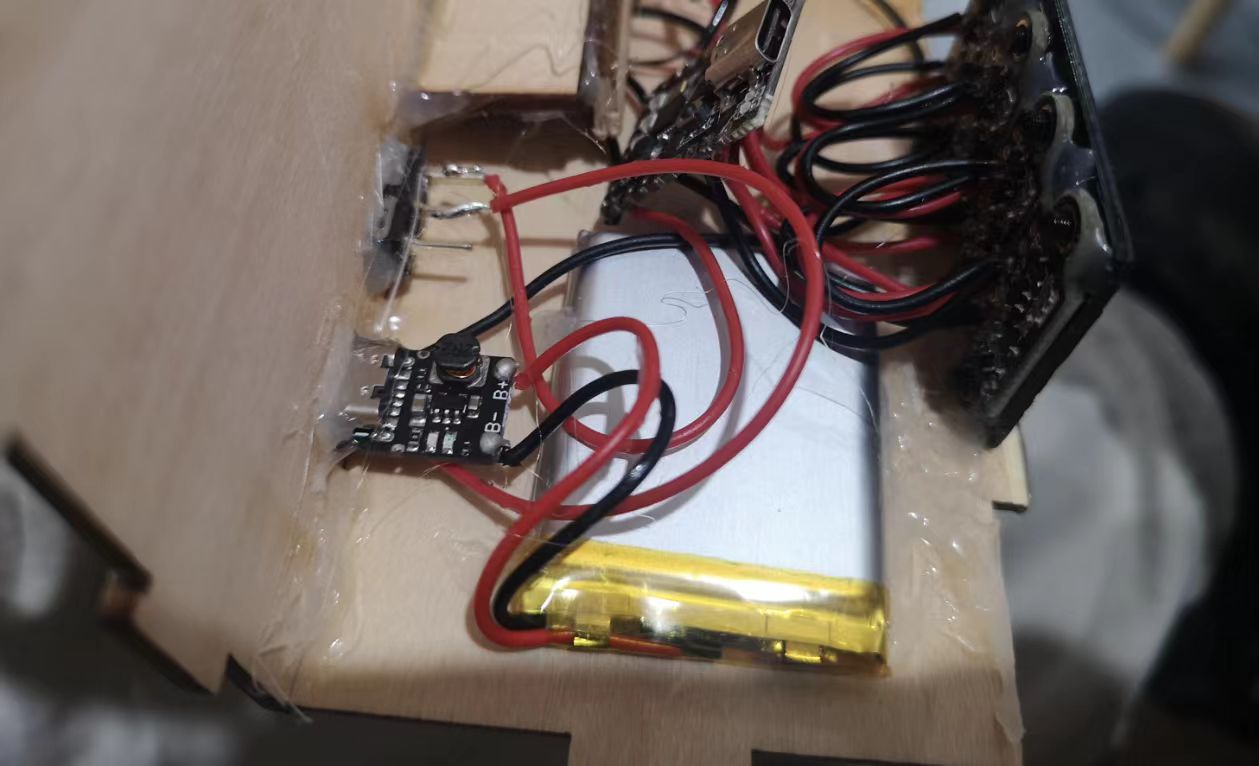
- Power layer — battery, charging board (5 V regulator included); USB-C port aligned with side cut-out.
- Electronics tray — custom PCB or Week 8-style carrier holds XIAO, TCA9548A breakout, and DFPlayer.
- Input panel — touch senosr on the side of the box.
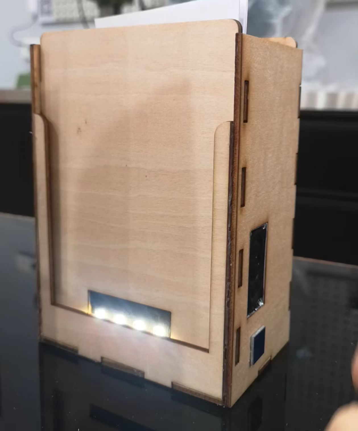
- Sensor deck — four TCS34725 boards fixed bottom part of frontside of the tray with 4 rectangular windows aligned to the photo colour strip path.
- Acoustic part — speaker on the right side of the box (planned to be moved inside in the future); DFPlayer SD card access through backside cut-out.
- Closure — top cover (rotary) + photo tray (standalone box) + base box, no screws (hot glue will be used); cable hidden inside the base box and outside the photo tray.
Interface risks I planned for:
- Protection for electronics: in the first edition, speaker and touchsensor will be exposed to the outside directly, so I need to add a cover for them for the 2nd edition.
- Audio vs I2C noise: speaker wires routed away from I2C; DFPlayer power decoupled near the module.
- Mechanical ↔ optical: photo must sit at repeatable height → a outside groove rail for photo to slide on → colored strips on the photo edge.
- Serviceability: a cut-out for SD card swap, better to be a removable pannel and USB reprogramming without disassembling the whole box.
2. CAD and Sketches
I documented the integration with: early hand sketches, a subsystem block diagram (on the final project page), and CAD for the enclosure and internal volumes.
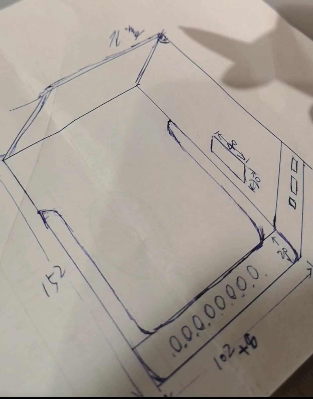
Hand sketch — overall (from project ideation; tray + shield + cover + speaker + sensors):
CAD — enclosure assembly
I modelled the shell in Laser Maker (2D for laser cutting) and Fusion 360 (3D) for different parts. Design choices driven by integration:
- Overall footprint ≈ 164 mm × 120 mm × 75 mm
- A rotary cover for the box
- A cut-out (50 mm × 32 mm) in the frontside for four TCS34725 apertures
- A cut-out (7.2 mm × 7.2 mm) in right side for touch sensor
- A cut-out (40 mm × 20 mm) in right side for speaker
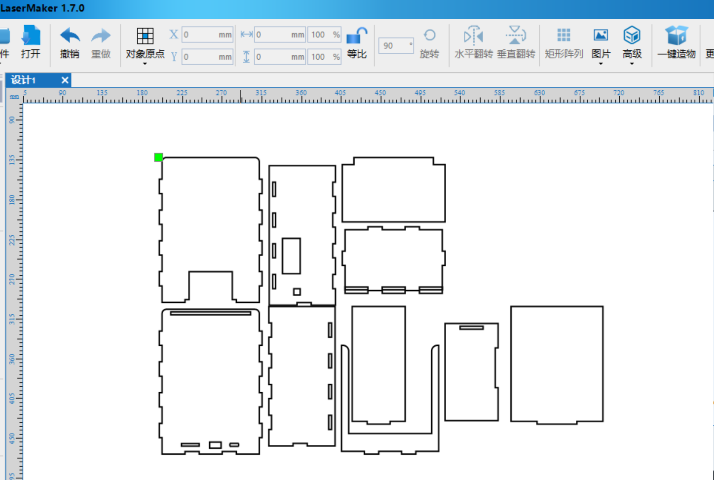
Integration sketch (draft):
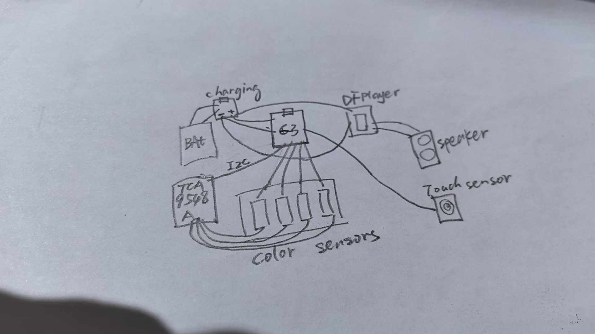
Wire routing diagram (logical):
XIAO I2C → TCA9548A → four color sensors;
XIAO UART → DFPlayer → speaker;
GPIO → touch sensor;
5 V rail → XIAO + DFPlayer + touch sensor;
GPIO → LED (if available);
GPIO → VCC for color sensors;
3. Packaging Methods
I chose woodboard packaging (laser-cut plywood, easier for prototyping) and some 3D printed parts. Methods implemented (or in progress) this week:
- Two-layered shell — outter + inner; I planned to use hot glue for assembly so no screws will be designed.
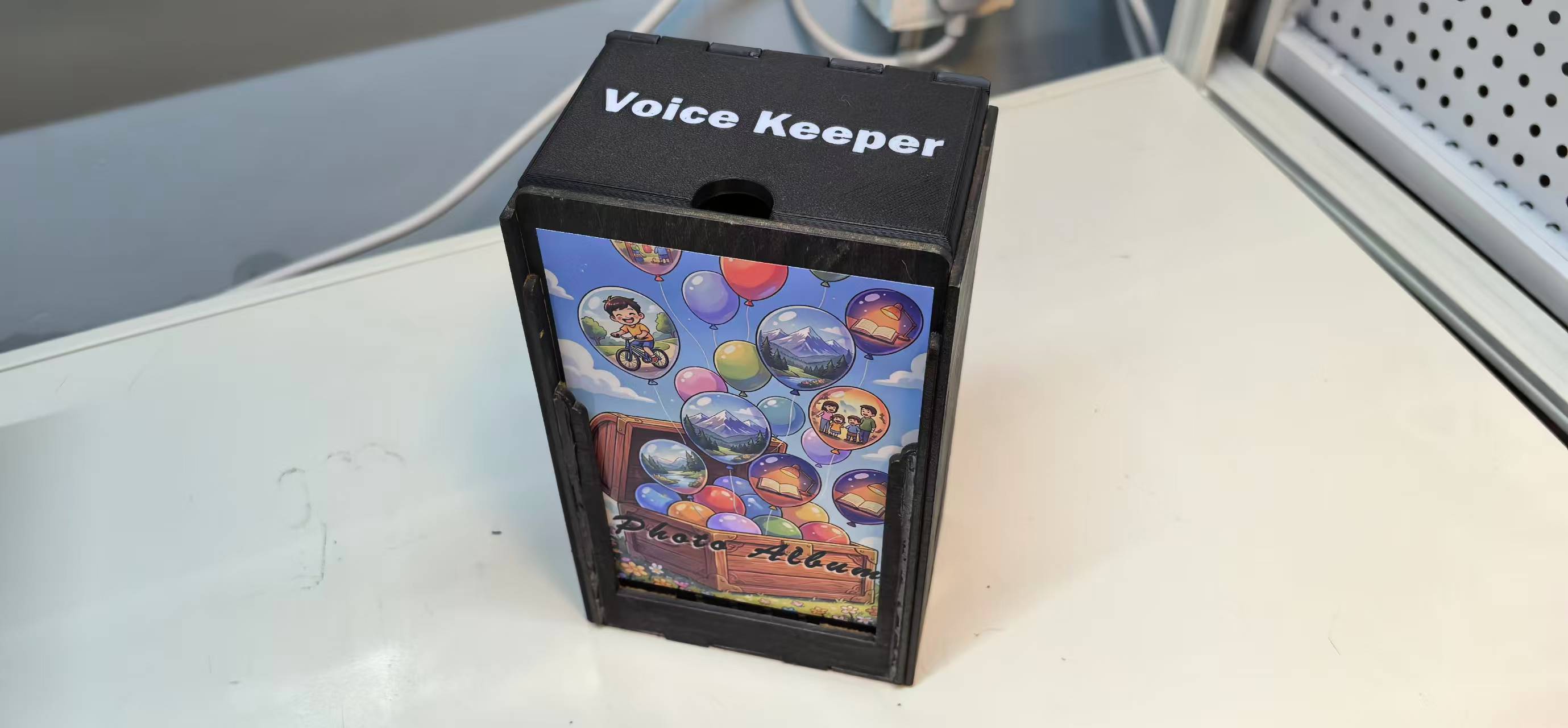
- User-facing materials — painted surface of the whole box and some decorations.
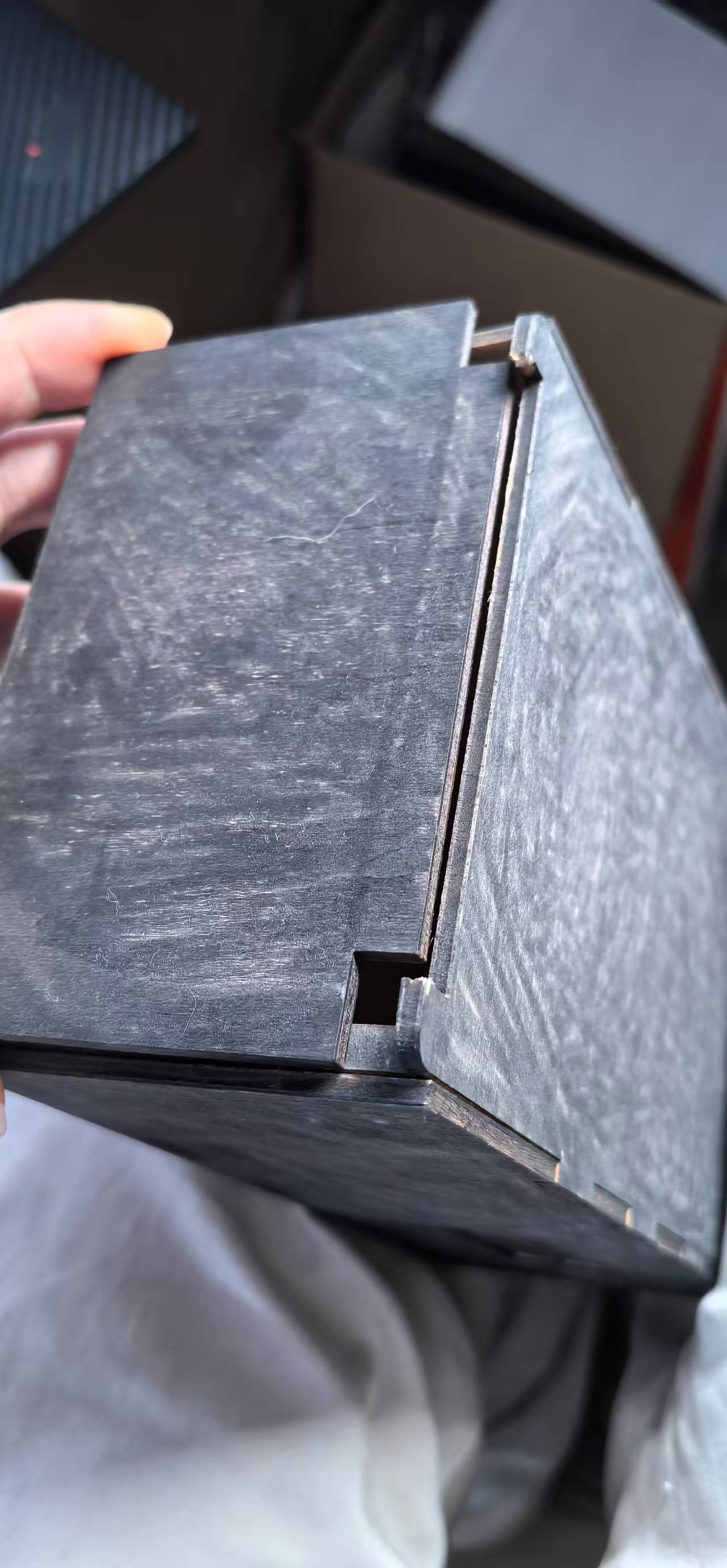
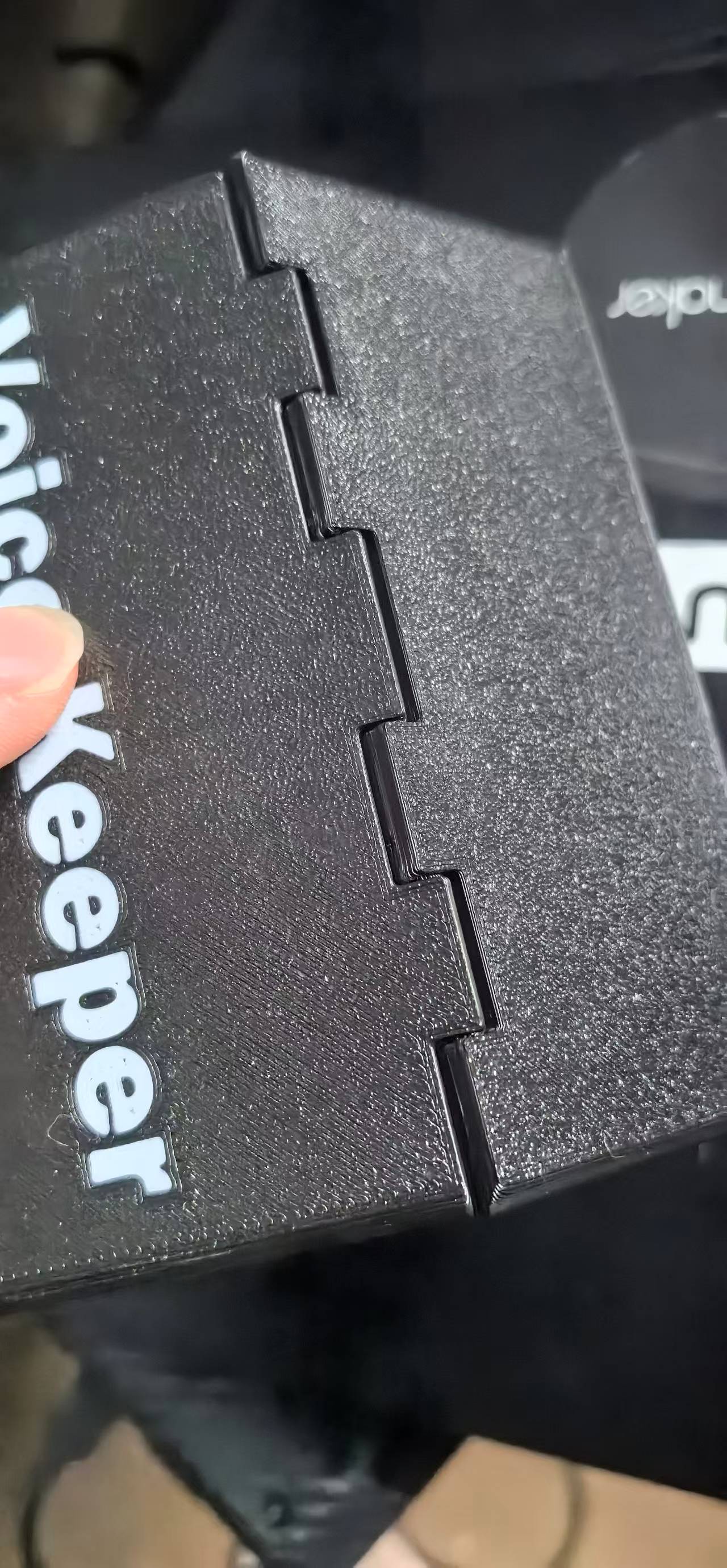
- Removable access — rotary cover for the photo tray.
How it looks without painted:
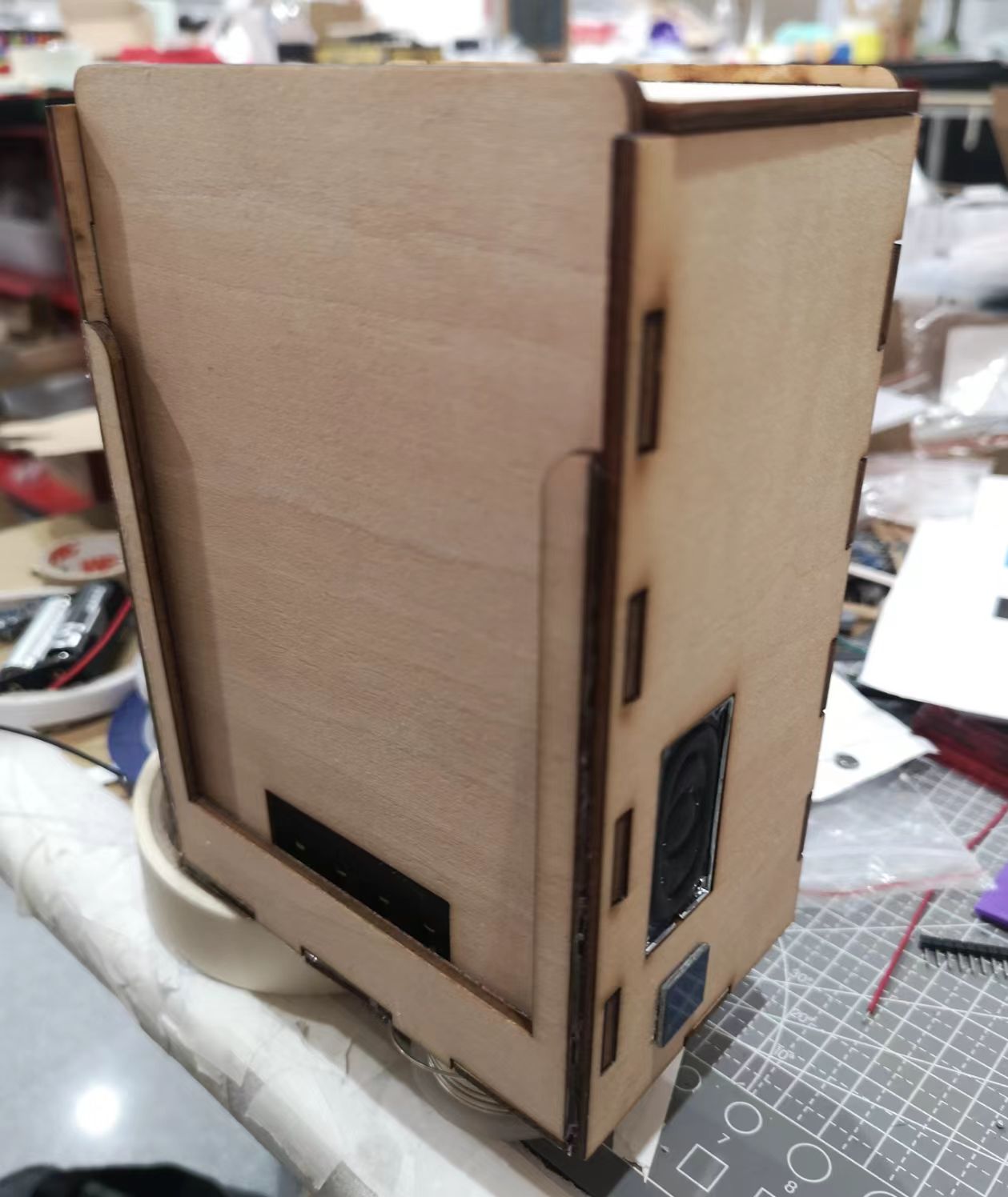
Then I painted the whole box and add some decorations:
The plywood version of the rotary cover:
But it got broken soon as the plywood was too soft, so I made a 3D printed version:
4. Finished-Product Design
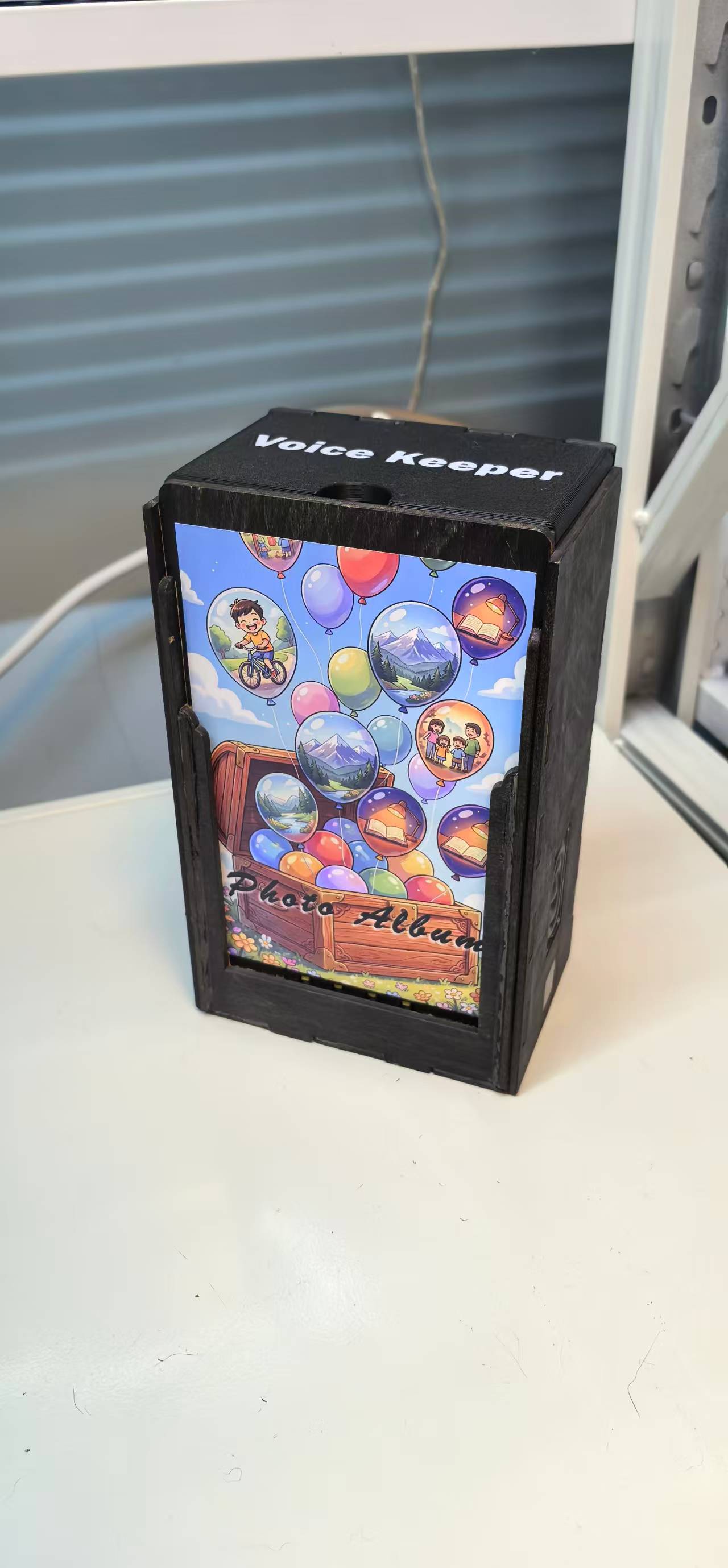
Voice Keeper is designed to read as a domestic object, not a developer kit. Design language:
- No screen — interaction is physical: photo, button (touch sensor).
- Warm, calm geometry — soft corner radii, front tray invites placing a photo like a picture frame.
- Hidden complexity — colour encoding is invisible to the user (strip on photo back and bottom edge); only the play button (touch sensor) is visible.
- Single-cable maintenance — USB-C on the back for charging; no dongles in normal use.
- Consistent colour palette — neutral shell (dark grey) so printed photos remain the visual focus.
- Large storage space — at least 120 photos can be stored in the box and audio in the TF card (microSD card).
Compared to my previous weekly assignments, the integrated unit hides the XIAO, other modules and all cables inside the base and side part of the box. That is the main “finished product” step for Week 15.
5. System Integration Documentation
Functional integration test plan (run after each assembly stage):
| Stage | Test | Pass criteria |
|---|---|---|
| Electronics bench | I2C scan + read 4 sensors | Stable quinary values for 5 reference swatches (RGBWK) |
| Electronics bench | UART play track by ID | Clear audio, no reset when speaker at 28/30 volume |
| Mechanical mock-up | Photo placement repeatability | Same ID ±0 when photo removed and replaced |
| Closed shell | End-to-end: photo → touch sensor (the play button) → audio | LED of color sensors on success, correct MP3 file plays |
| Battery power | Full session on battery | ≥ 30 min mixed play at 28/30 volume, chargable |
Final calibration and end-to-end test results
Integration tests run on the closed Voice Keeper unit after assembly (May 2026):
| Test | Result | Evidence |
|---|---|---|
| I2C + 4× TCS34725 via TCA9548A | Pass — stable raw RGB/clear per swatch on bench and in box |
|
| UART → DFPlayer, volume 28/30 | Pass — clear audio, no MCU reset during playback | Test video |
| TTP223B touch → play trigger | Pass — one audio event per touch-release cycle |
Test video Touch sensor tested in Week 09 |
| End-to-end: photo → touch → correct MP3 | Pass on demo photo set (IDs 1–4, 11, 111, 1111) |
Open in new tab ↗ |
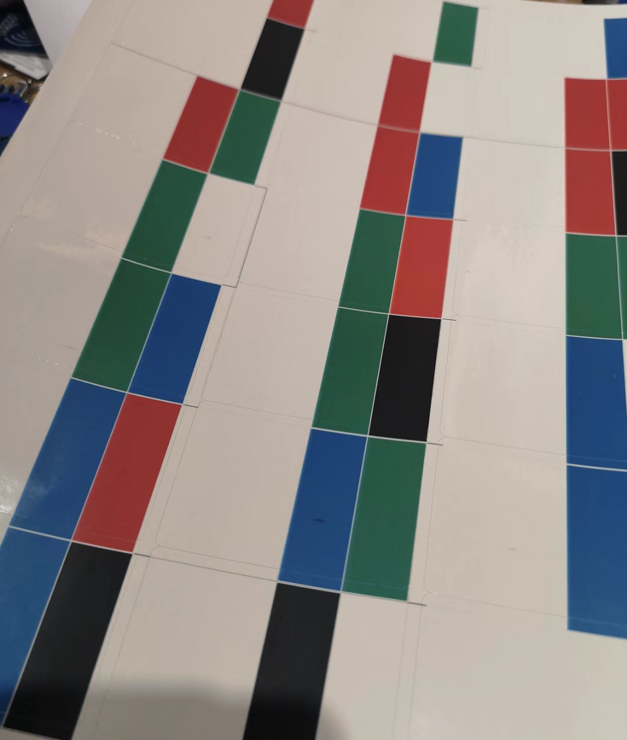
| Quinary colour calibration | Pass — Black/White/Red/Blue/Green reliable; tried other colors, not working well — kept 5 colours as final version |
final_firmware.ino |
| Battery session ≥ 30 min mixed play | Pass — USB-C charge verified; runtime test scheduled |
|
Merged firmware: final_firmware.ino (touch → read colours → DFPlayer + optional Web UI). Remaining v2 work: speaker/touch covers, full 625-ID calibration under domestic lighting.
Software integration: one main loop on the XIAO — (1) setup and turn AP on, (2) on touch sensor debounce read sensors via multiplexer, (3) compute quinary ID, (4) send play command to DFPlayer. Subsystems tested separately in Weeks 8–11 are merged here. Week 15 web UI adapted for DFPlayer setup.
Bill of materials (integrated unit):
XIAO ESP32-C3 × 1,
TCA9548A × 1,
TCS34725 × 4,
DFPlayer Mini × 1,
8 Ω 2W speaker × 1,
TTP223B (touch sensor) × 1,
Li-ion + Charge board × 1,
switch (power on/off) × 1,
custom/Week 8 PCB × 1,
printed enclosure (PLA),
3mm thick plywood,
TF card (microSD card) × 1
6. Link From Final Project Page
System integration documentation is linked from the final project outline under System Integration, which points back to this Week 16 page for weekly-assignment credit and for anyone reading the final project top-down.
What I Learned
Integration is scheduling, not only soldering. The order of assembly also matters.
CAD is a communication tool. Sometimes I still prefer thinking in mind and do hand sketches, but CAD and simulation can help me to see the whole picture and find the problems before assembly.
Packaging is electrical engineering. Power module should provide enough power for all the components; color of the frame for color sensors were a mechanical fix for an optical problem.
Finished look comes from details: hidden cables, dark color of the whole box, and a single USB port on the back matter as much as the colour-encoding algorithm for whether the project feels “real.”