Input Devices
Here is the link to our group assignment:
Week 9 Group Assignment — Input Devices.
This week we probed input devices with a multimeter, oscilloscope, and logic analyzer to see how physical actions become voltages and digital waveforms on the microcontroller pins. The notes below document what I learned from that group work and from my individual assignment: a TTP223B touch sensor on the Week 8 PCB controlling two LEDs.
Group Assignment — What We Measured
In the group session we used the Seeed Grove ecosystem and treated each capture as lab evidence. The goal was not to build a product, but to understand how different sensors behave electrically before firmware reads them.
We characterized several input types together:
- Grove rotary angle sensor (potentiometer) — slow analog DC, voltage follows knob angle
- Grove button — digital contact with mechanical bounce on press/release
- Grove rotary encoder — two quadrature square waves, phase shows direction
- Grove RTC (DS1307) and I²C OLED — I²C bus traffic on SCL/SDA
- Grove GPS (Air530) — UART NMEA text at 9600 baud
Full scope screenshots, logic-analyzer decodes, and bench notes are on the group assignment page.
What I Learned — Physical Property vs. Measured Result
The main lesson for me was that every input device is a translator from physics to numbers the MCU can read:
- Analog inputs (potentiometer): rotating the shaft changes resistance → the wiper voltage moves smoothly between 0 V and 3.3 V. On the scope this looks like a slow ramp, not a sharp step. The measured ADC value is proportional to angle.
- Digital contact inputs (button): pressing closes a mechanical switch. The pin does not jump cleanly from HIGH to LOW — we saw bounce (rapid chatter) before the level settled. That is why firmware needs debouncing, which I also used on my Week 8 PCB (see Week 8).
- Quadrature encoder: rotation produces two square waves 90° apart; which edge comes first tells you direction. The physical detent clicks map to predictable A/B cycles.
- Bus protocols (I²C, UART): the physical property is timed voltage patterns on shared wires. A logic analyzer decodes meaning (address, data bytes, ASCII sentences) that a scope alone does not label.
Practical habits from the group work: tie scope/logic-analyzer ground to circuit ground first; check Grove cable order (GND, VCC, SIG) before power-on; note volts/div, time/div, and trigger level when saving screenshots so results can be reproduced later.
Individual Assignment — TTP223B Touch Sensor
For the individual assignment I added an input device to the microcontroller board I designed and milled in
Week 8. Instead of the tactile button used in Week 8 testing, I connected a TTP223B capacitive touch module and used the two LEDs already on that board as outputs for feedback.
Hardware (Week 8 PCB + touch module):
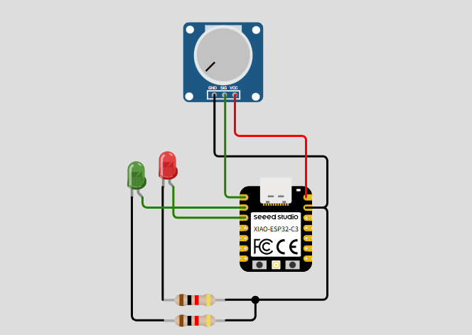
- MCU: SEEED XIAO ESP32-C3 (soldered on my Week 8 board)
- Touch input: TTP223B signal → D0 (idle LOW, touch → HIGH)
- LED1: D1 (
ledPinin code) - LED2: D2 (
ledPin2in code) - Power: TTP223B VCC to 5 V, GND common with the XIAO
Here is the hardware image:
Physical property → measured result: the TTP223B pad detects a change in capacitance when my finger is near or on the surface. The onboard IC toggles a digital output — no mechanical movement. On the scope (and in Serial Monitor) I see a clean LOW→HIGH edge when I touch, and HIGH→LOW when I release. Unlike the Week 8 push button, there is almost no mechanical bounce, but the output can stay HIGH for the whole time my finger is on the pad, so firmware must count one touch per press-and-release, not one per loop while held.
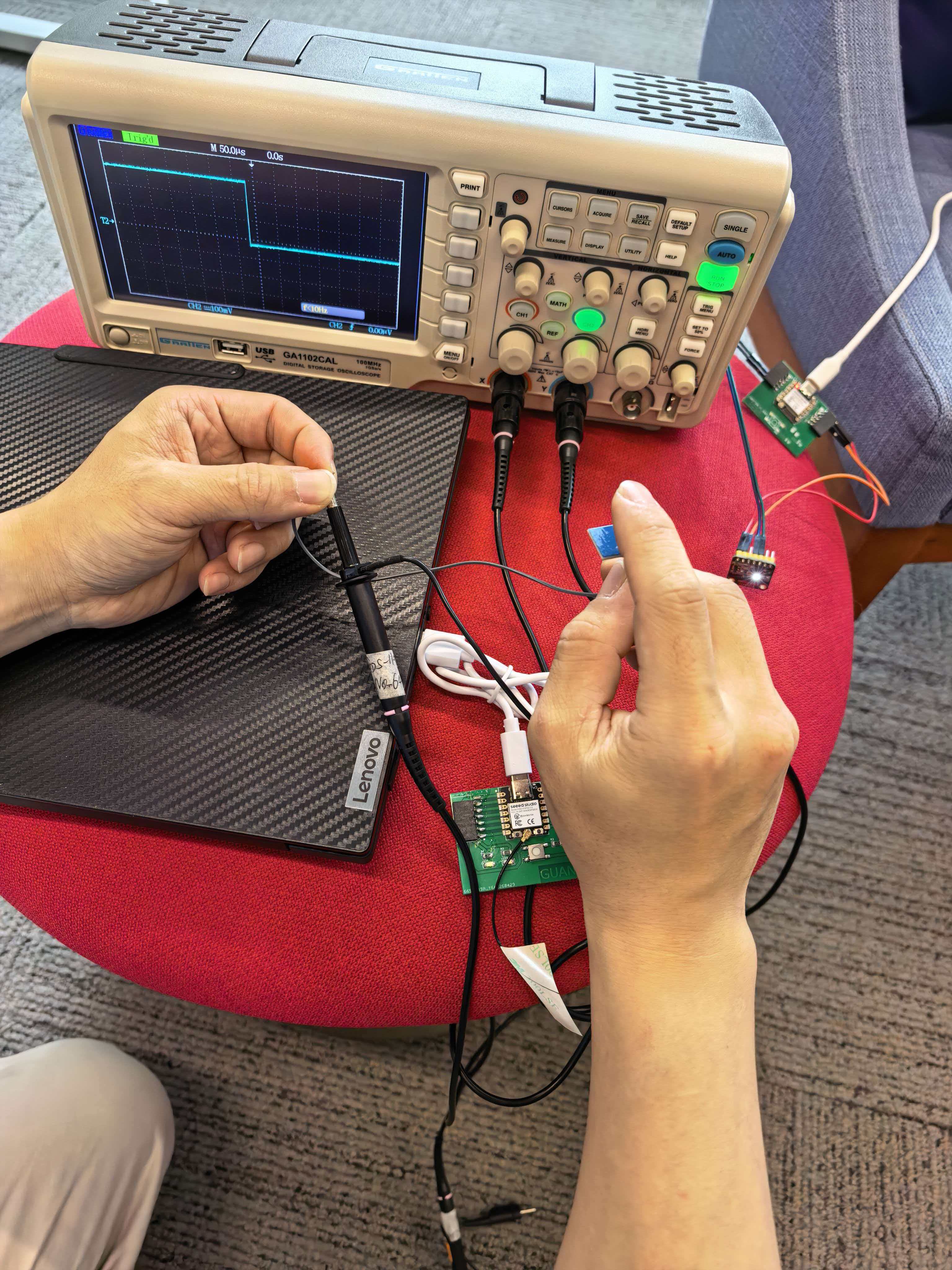
Oscilloscope capture (TTP223B on D0): using the same OWON scope procedure from
Week 9 group work (probe GND to board GND, trigger inside signal swing). One touch cycle shows a clean digital edge — idle ~0 V, touched ~3.3 V, rise/fall within one division; no multi-ms bounce like the Grove button in group tests.
Here is a video of the oscilloscope capture:
Program behaviour (repeating 3-step pattern):
- 1st touch — LED1 (
D1) turns on for 0.5 s, then off - 2nd touch — LED2 (
D2) turns on for 0.5 s, then off - 3rd touch — both LED1 and LED2 turn on for 0.5 s, then off
- 4th touch and after — the same cycle repeats (LED1 → LED2 → both → …)
Source file: ttp223_touch.ino
Code
The sketch reads the touch pin, detects a new touch only once per contact (using touchLatched until the signal returns LOW), increments a counter, and maps touchCount % 3 to which LEDs pulse for 500 ms.
const int touchPin = D0;
const int ledPin   = D1;   // LED1
const int ledPin2  = D2;   // LED2

const unsigned long LED_ON_MS = 500;

int touchCount = 0;
bool touchLatched = false;

void pulseLeds(bool led1On, bool led2On) {
  digitalWrite(ledPin, led1On ? HIGH : LOW);
  digitalWrite(ledPin2, led2On ? HIGH : LOW);
  delay(LED_ON_MS);
  digitalWrite(ledPin, LOW);
  digitalWrite(ledPin2, LOW);
}

void setup() {
  pinMode(touchPin, INPUT);
  pinMode(ledPin, OUTPUT);
  pinMode(ledPin2, OUTPUT);
  Serial.begin(115200);
}

void loop() {
  int touch = digitalRead(touchPin);

  if (touch == HIGH && !touchLatched) {
    touchLatched = true;
    touchCount++;
    int phase = touchCount % 3;

    if (phase == 1) {
      pulseLeds(true, false);   // 1st touch → LED1
    } else if (phase == 2) {
      pulseLeds(false, true);   // 2nd touch → LED2
    } else {
      pulseLeds(true, true);    // 3rd touch → both
    }
  }

  if (touch == LOW) {
    touchLatched = false;       // ready for next touch
  }
}
This is the video of the input device:
Relation to my final project: Voice Keeper may use a touch or play control on the side of the box. This test showed me that capacitive touch gives a clean digital signal but needs edge/latch logic so one finger contact equals one event — similar to debouncing a mechanical button, but waiting for release instead of filtering bounce.
Tactile Button on My Week 8 Board (Earlier Test)
In Week 8 I already interfaced a tactile push button on the PCB I milled and soldered myself. The physical action is mechanical contact: press = connect, release = open circuit. With a pull configuration on GPIO D0, the firmware reads HIGH or LOW and uses a 50 ms debounce timer before counting presses or driving LEDs.
During group probing we saw the same bounce pattern on a Grove button at the pin — that confirmed why my debounce code in Week 8 was necessary, not optional. Details and test video are documented on my Week 8 assignment page.
Summary
From Week 9 I learned to think in two steps: (1) what physical quantity changes (angle, contact, capacitance, serial bits), and (2) what voltage or waveform the microcontroller actually samples. Group work with the scope and logic analyzer made that link visible; my TTP223B touch test on the Week 8 board — with the LED1 / LED2 / both pattern — turned that into working firmware I can reuse in later weeks and in my final project.