Electronics Design
Group Assignment — Measurement Tools
Here is the link to our Group assignment:
Week 6 Group Assignment — Electronic Measurement Tools.
In the group session we used a multimeter (parallel voltage across ESP32 VCC/GND → 5.00 V; series current through GPIO 19 → 2.78 mA) and an oscilloscope (PWM servo waveform — pulse width vs angle). The oscilloscope session was particularly eye-opening: watching the square wave shift as the servo moved from 0° to 90° made pulse width and duty cycle visually concrete.
Logic analyzer (documented on Week 9 group page): our lab also used a logic analyzer in
Week 9 — Group Assignment (Input Devices) to decode digital buses (I²C on Grove OLED/RTC, UART on GPS NMEA, quadrature encoder A/B). I participated in that session — captures are on the Week 9 group page; I link them here so the full group equipment set (multimeter, scope, logic analyzer) is visible from my Week 6 page as well. The logic analyzer adds labeled byte streams on SCL/SDA and TX/RX beyond what the scope decodes automatically.
Working collaboratively accelerated learning — e.g. spotting loose ground when a probe looked unstable. These measurement skills feed directly into my Week 8 PCB bring-up and final project debugging.
EDA Tool
I will use LCEDA to design the electronics.
Here is the official website of LCEDA: LCEDA
I designed a simple board for XIAO_ESP32-C3, it's a single layer board, I've connected two LEDs and a button, I also designed the Dupont wire connector female ports for the board.
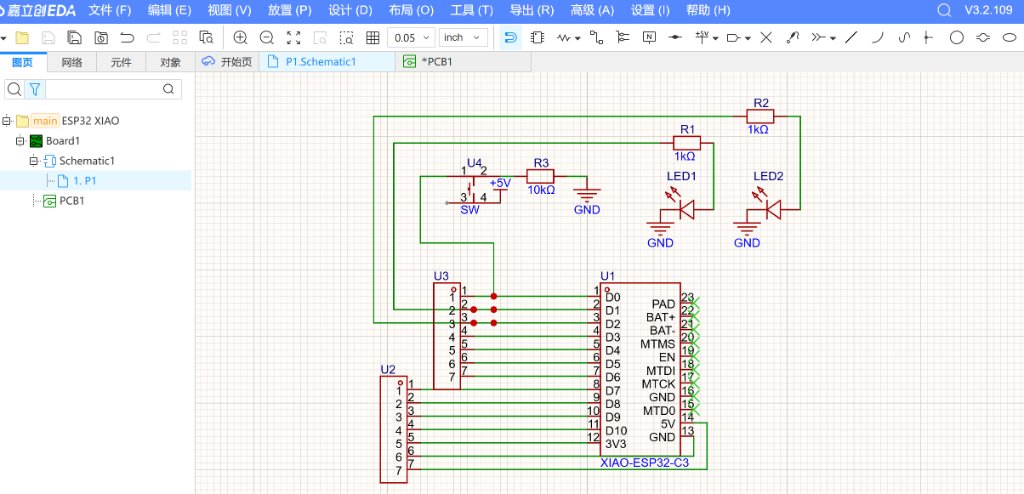
The above image is the schematic of the board, the follow is the PCB design.
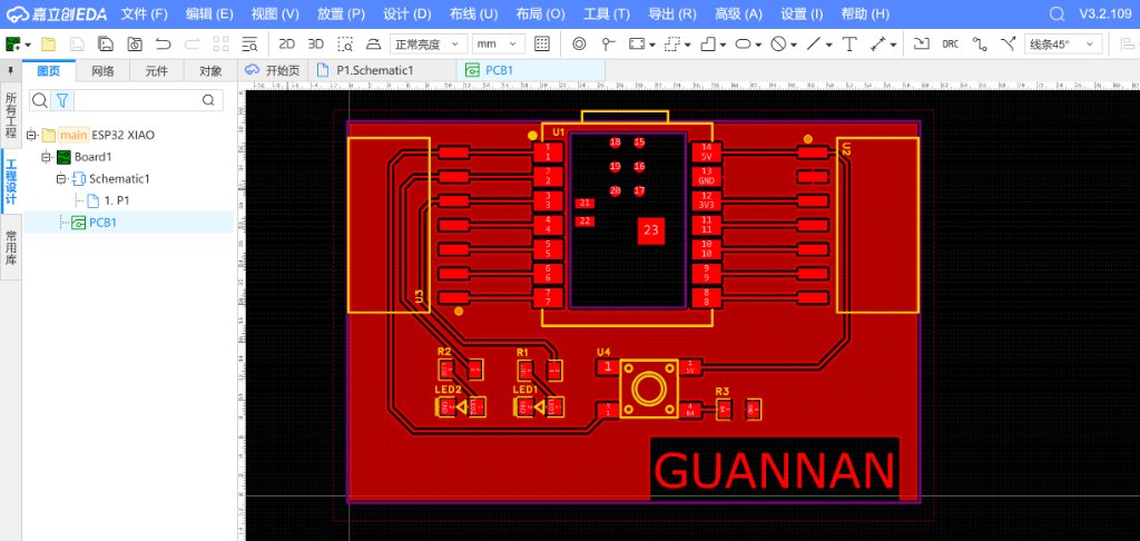
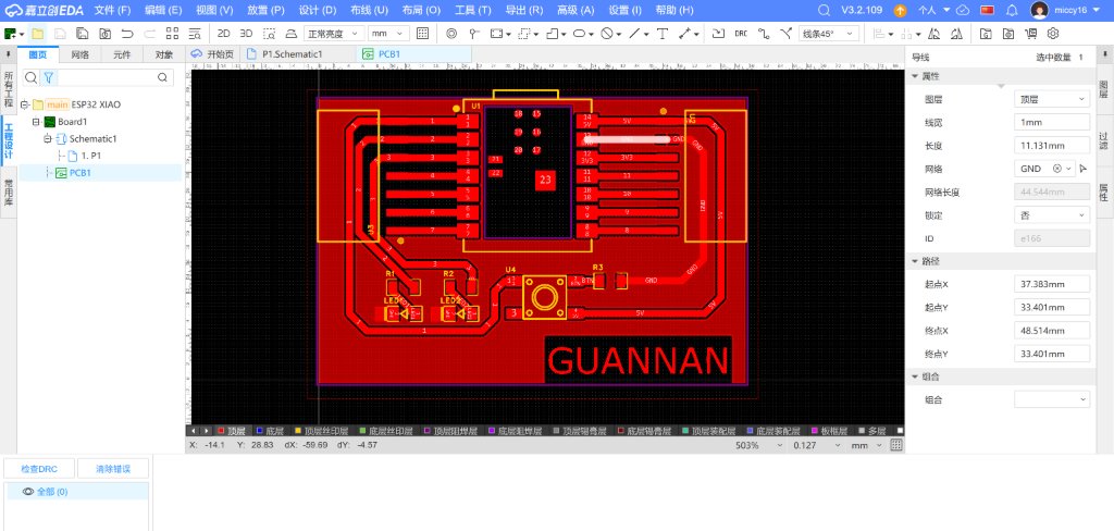
I used the DRC check function to check the design, when there was no error, Which means the design is correct, I could export the PCB file.
Here is the PCB design files (gerber files): Gerber_Guannan.zip