3D scanning and printing
3D scanning
To use a scanner to scan should get a better result, but a mobile APP might be more convenient.
In our lab, we have a 3D scanner, it's a Creality Raptor Pro.
Here is the manual of it: Creality Raptor Pro Manual
It's complicated to use, but it's a good scanner. We are still learning how to use it.
In the Makerlab of MakerWorld, there is an interesting AI function to scan and generate 3D model. We could also try it.
Here is the link:MakerWorld AI Scan
I tried to scan a roll of filament by using the MakerLab AI Scan.
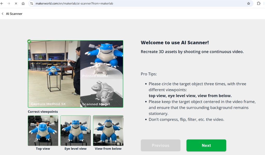
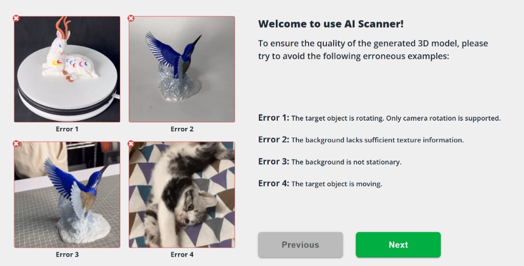

I've shoot a video by following the guide. Here is the video:
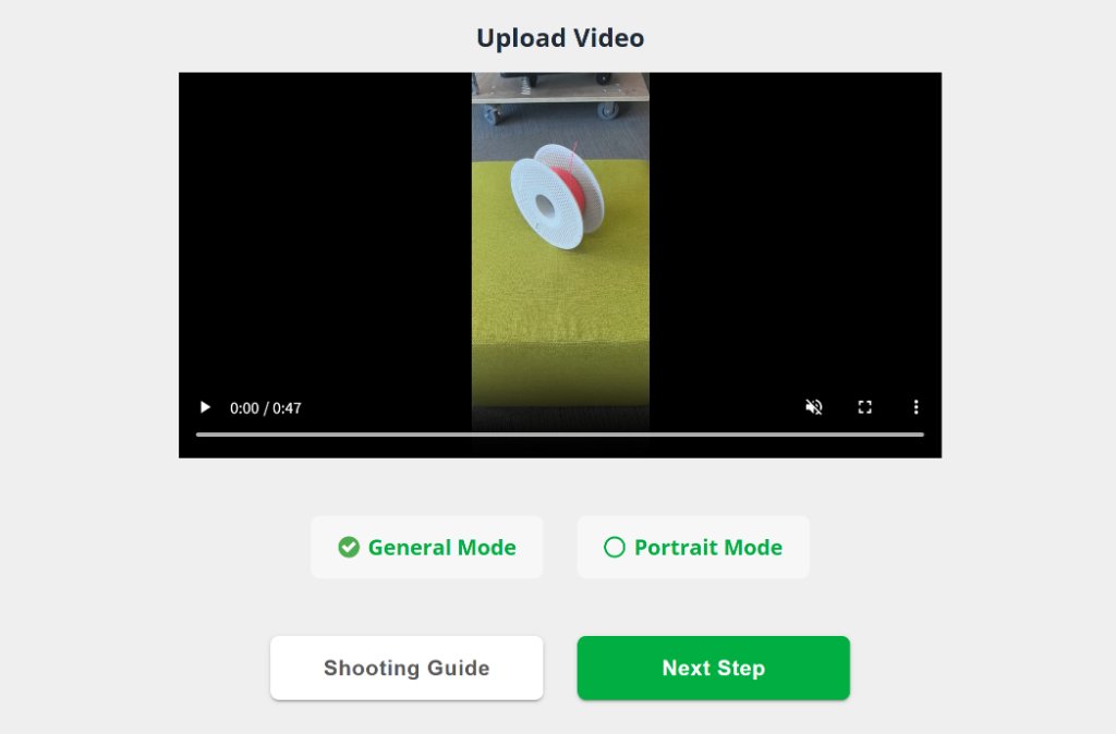
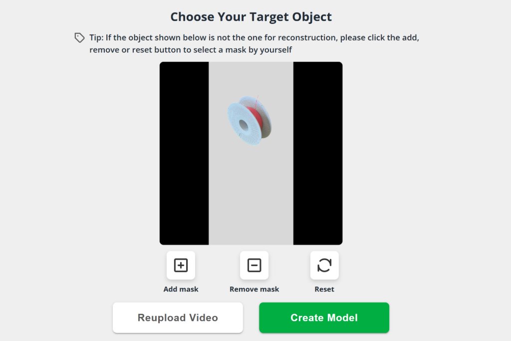

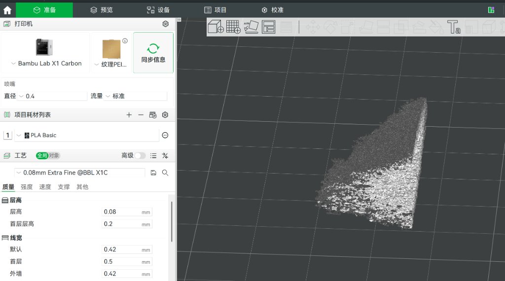
The result was not good, I need a better scanning tool.
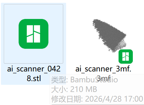
The file size is too large, I will not upload it here.
3D Printers
Here is the link of our Group assignment: Week 5 Group Assignment
Testing five distinct printers—Creality K2 Plus, Bambu X1C, A1 mini, P1S, and H2D—across benchmarks including overhang limits, bridging distance, dimensional accuracy, flow consistency, and maximum viable speed revealed that raw specifications rarely tell the full story. The K2 Plus impressed with its massive build volume and CoreXY motion system, yet I learned that scale demands meticulous calibration; without proper bed leveling and flow tuning, larger prints amplify tiny errors into visible layer inconsistencies.
Bambu Lab's lineup demonstrated clear tiering: the X1C delivered flagship consistency with its actively heated chamber and AI inspection, producing clean 70-degree overhangs effortlessly. The P1S offered reliable enclosed printing at a lower cost, though its bridging across 100mm spans required careful cooling optimization to avoid sagging. The compact A1 mini proved surprisingly capable for its size, handling miniatures with impressive detail despite its open frame and limited build plate. The newer H2D introduced aggressive speed capabilities, but I discovered that pushing acceleration beyond 20,000 mm/s² compromised surface finish on complex geometries, forcing me to balance time savings against aesthetic quality.
Ultimately, this exercise taught me that effective 3D printing is about matching machine strengths to project requirements rather than chasing perfect specifications. Understanding each machine's unique personality—where it excels and where it compromises—is far more valuable than comparing numbers on a datasheet.
In our lab (in Beijing), we have Creality K2 Plus, Bambu X1C, Bambu A1 mini, Bambu P1S and Bambu H2D.
K2 Plus has a larger build volume, so I can print larger 3D model with it.
U1 has four nozzles, so I can print multi-color 3D model with it without waste of flushing.
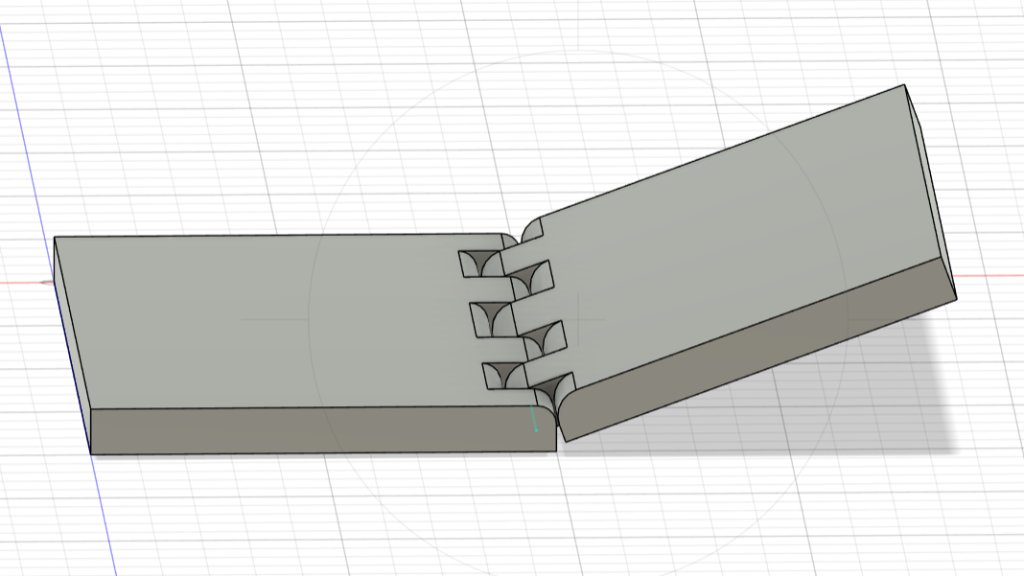
I've tried to make a rotary cover for a box. There is no need to be assembled, so it's printed as a whole.
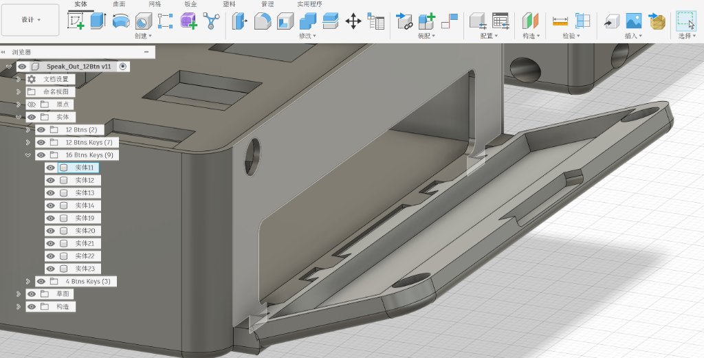
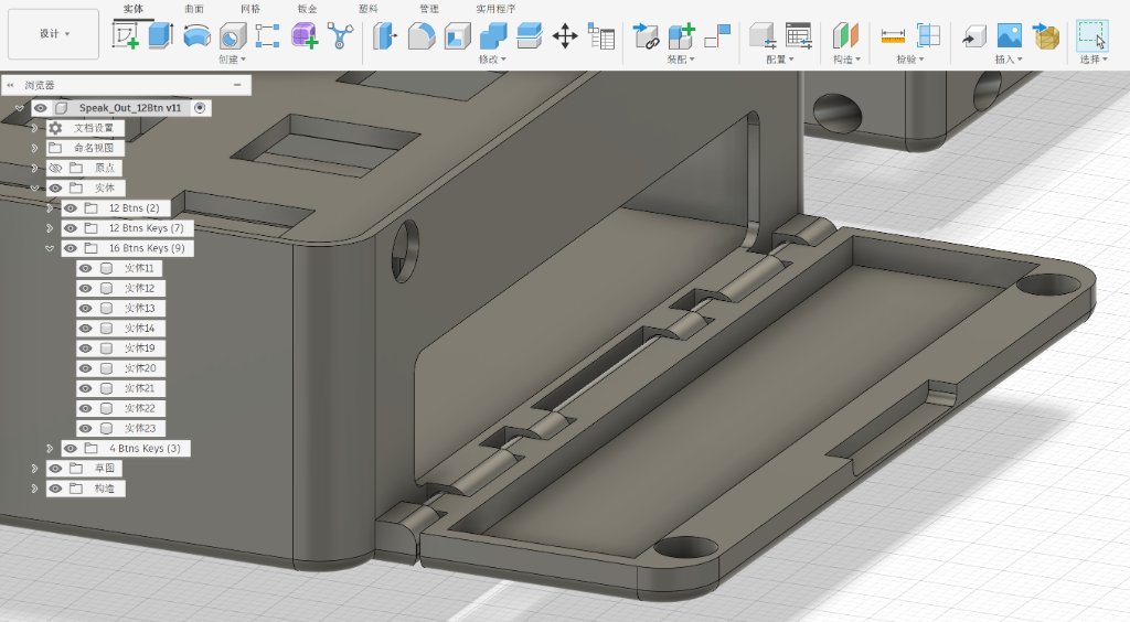
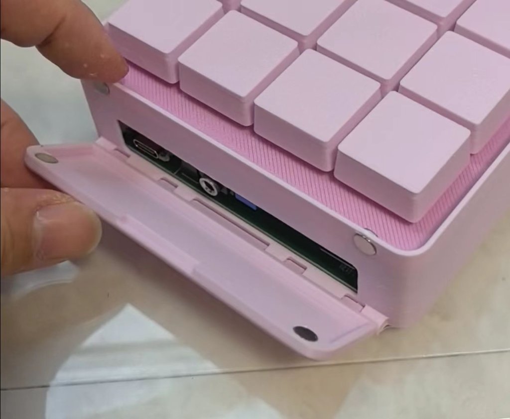
For this structure, if we are thinking about to make it subtractively, the rod needs to be made separately and then assembled.
For my understanding, most of the stuff could be made both additively and subtractively. It depends on the design and the purpose of the product.
We could not tell which one is always better. It depends on the specific case. For the above design, I used PLA to 3D print the model, it could be printed as a whole and easily to get mass-produced, the cost is quite low and I could easily modify new designs, but PLA is not strong enough. If it's broken, it might not be able to be repaired. As it's cheap, I could always print a new one.
If we want to use a strong material, like PETG-CF, or nylon, or even metal, it would be quite expensive.
If we made it subtractively, I might need to prepare all separate parts and then assemble them. But I could choose a strong material for the rod (like metal) to make it more durable and less likely to be broken.
Here is the original file of the design: Design01.stl
As my instructor suggested, I should add more detailed steps to show how to make the model. Here are the steps for making the rotary structure.
First, I opened Fusion 360 to start a new sketch. A simple rectangle was created, with the size of 100mm x 50mm.
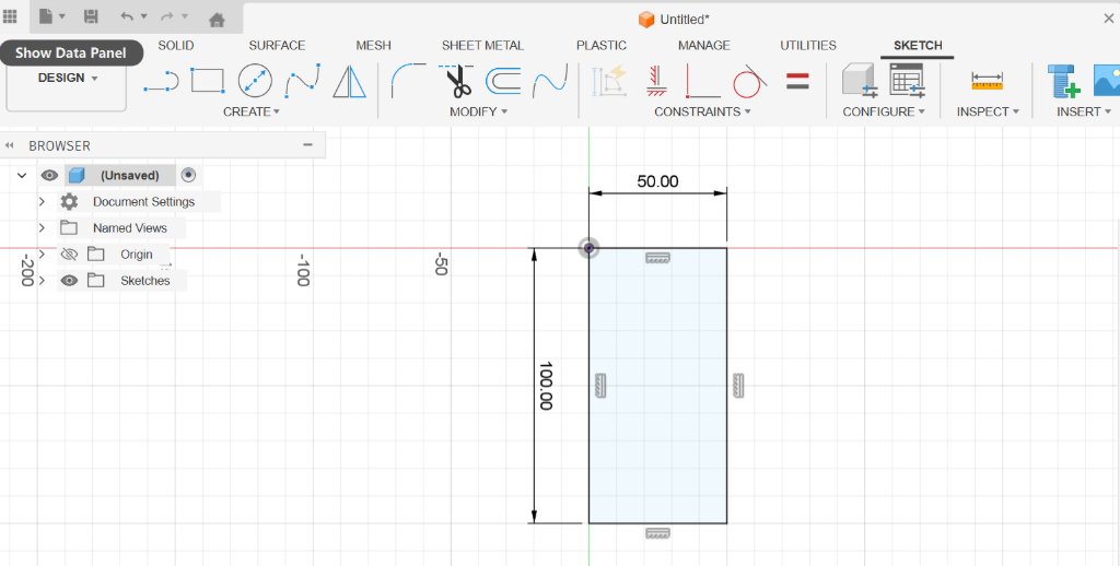
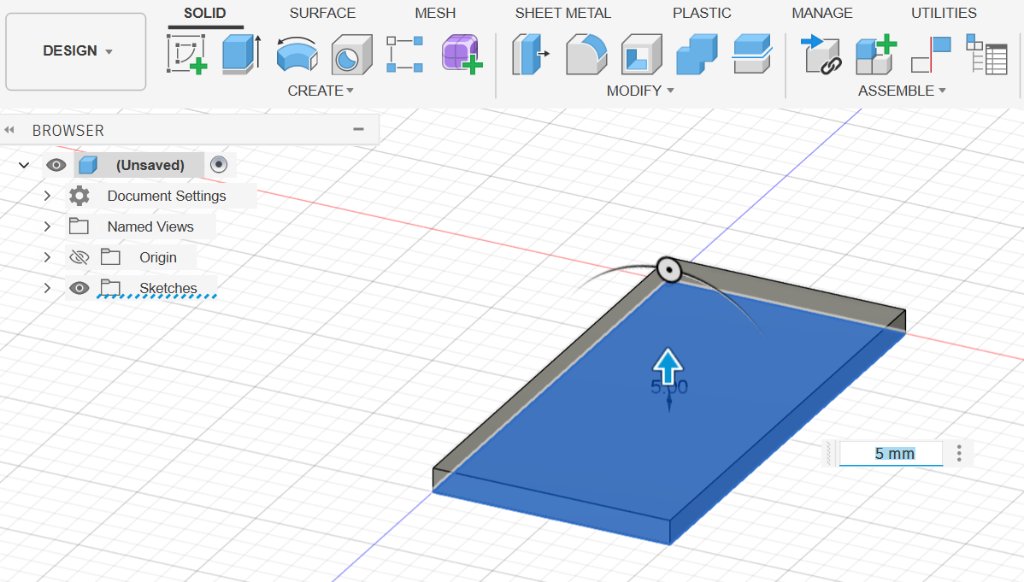
I used "Extrude" to create a solid prism, with the height of 5mm.
On the top surface of the prism, I made a new sketch, three rectangles were created on one side. I made the length as 15mm, 20mm and 15mm, with the gap between each other as 10mm.
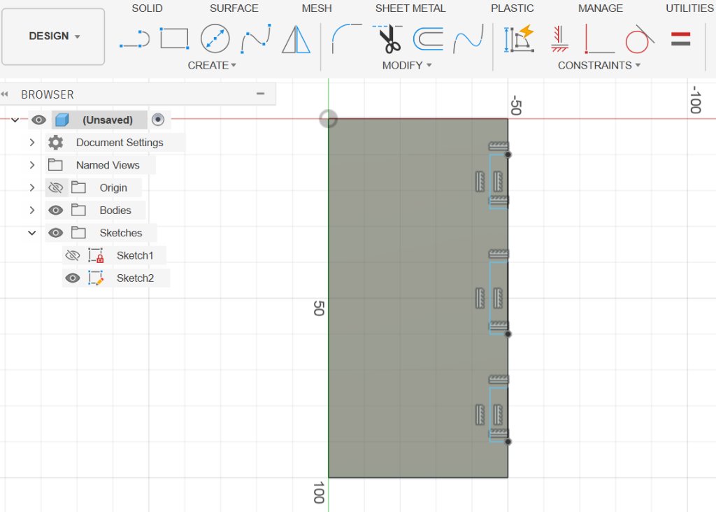
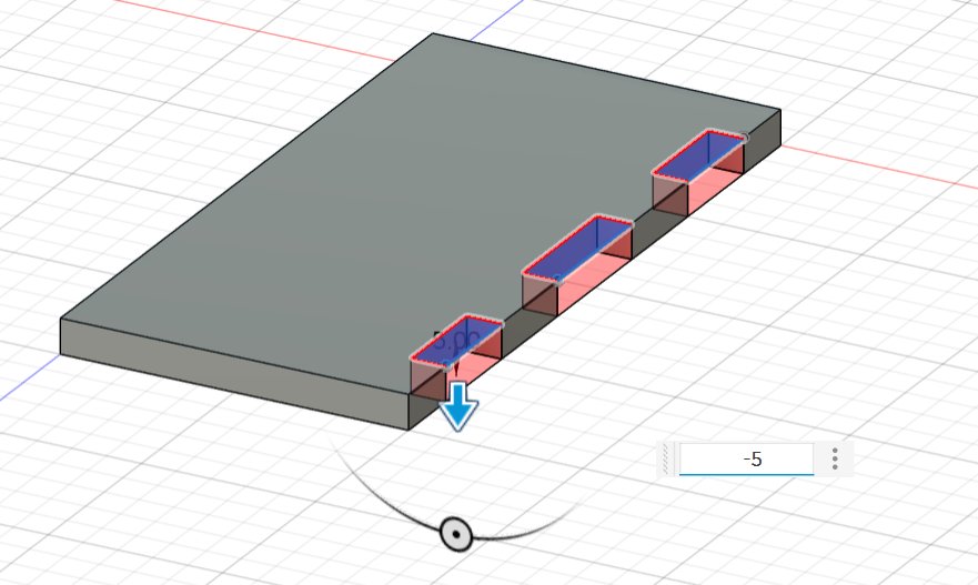
Then I used "Extrude" to cut the prism to make the "teeth".
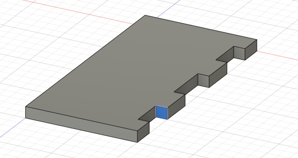
Select any of the side of the "teeth", then I created a new sketch on the side. The side was a squared shape with the length of 5mm.
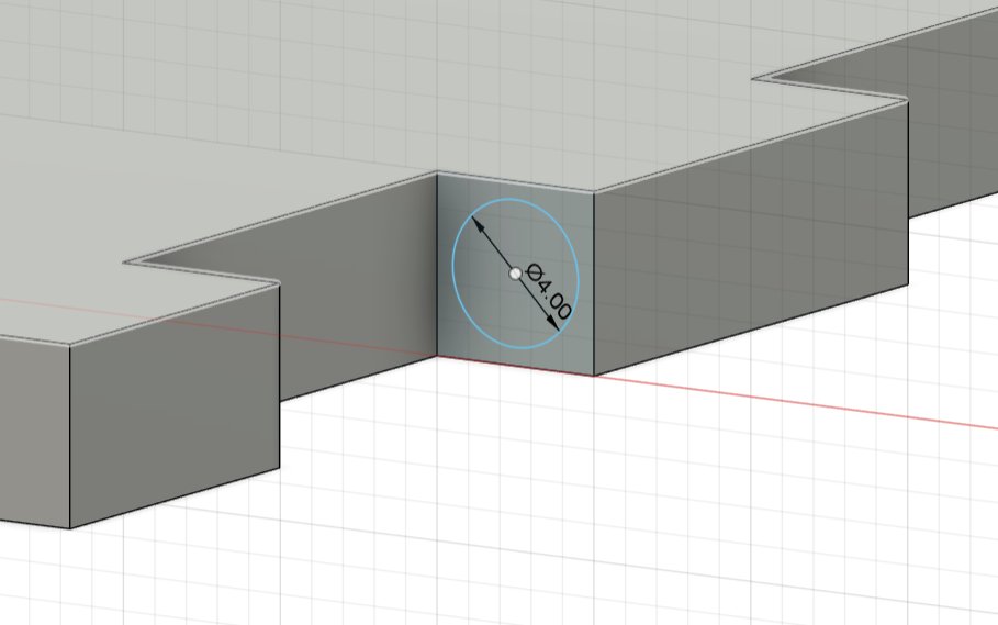
A circle was created, with the radius of 2mm and the center of the circle was at the center of the square.
Then I used the "Extrude" to cut the teeth to make the "holes", the direction should be "2 sides". The distance needed to be calculated well, for both ends, 2mm will be saved.
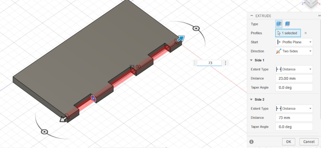
I chose the top surface of the prism again to make a new sketch.
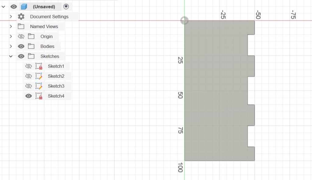
I used the "Offset" tool to offset the top surface borders of 0.3mm outside.
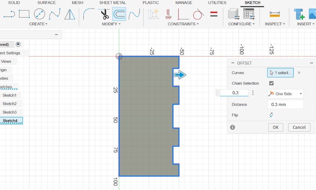
I put a 100mm x 50mm rectangle on the right side to make a overlap with the offseted teeth.
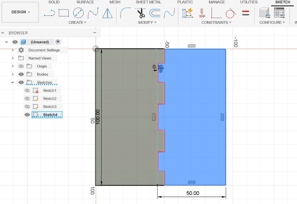
Then I used the "Extrude" tool to pull up the right side.
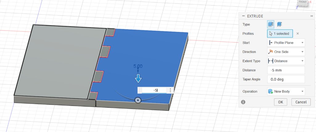
Then we could see two bodies.
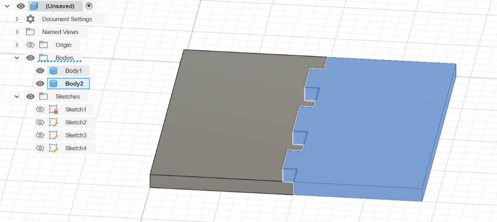
I hided the body 1 to make the following editing on body 2 easier.
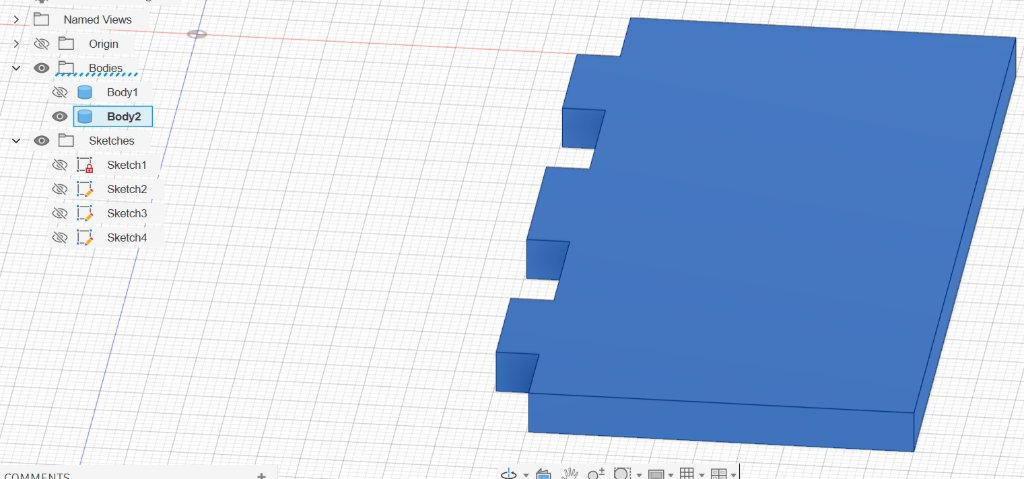
I chose the side of the teeth on body 2 to make a new sketch.
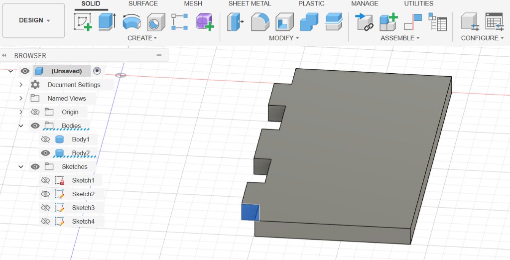
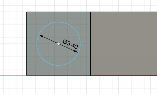
I added a circle with the diameter of 3.4mm, this would be the rod and the gap between the rod and the hole should be 0.3mm.
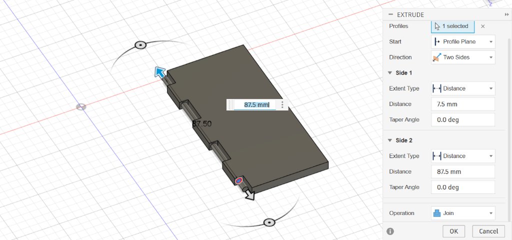
Then I used the "Extrude" tool to pull up the circle to make the rod, also chose the direction as "2 sides". The total length of the rod should be 1mm shorter than the hole depth.
I showed body 1 again and made the transparency of body 1 as 0.5 to make the two bodies more visible.
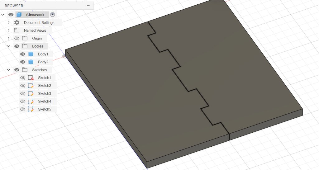
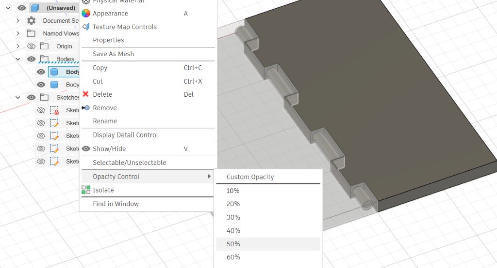
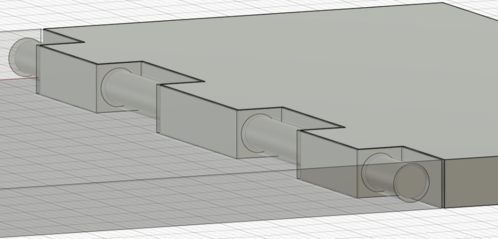
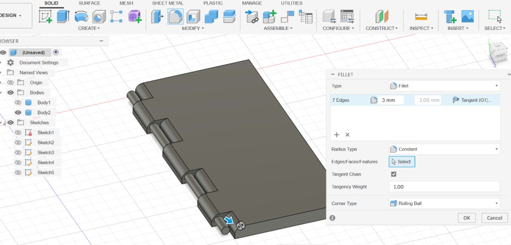
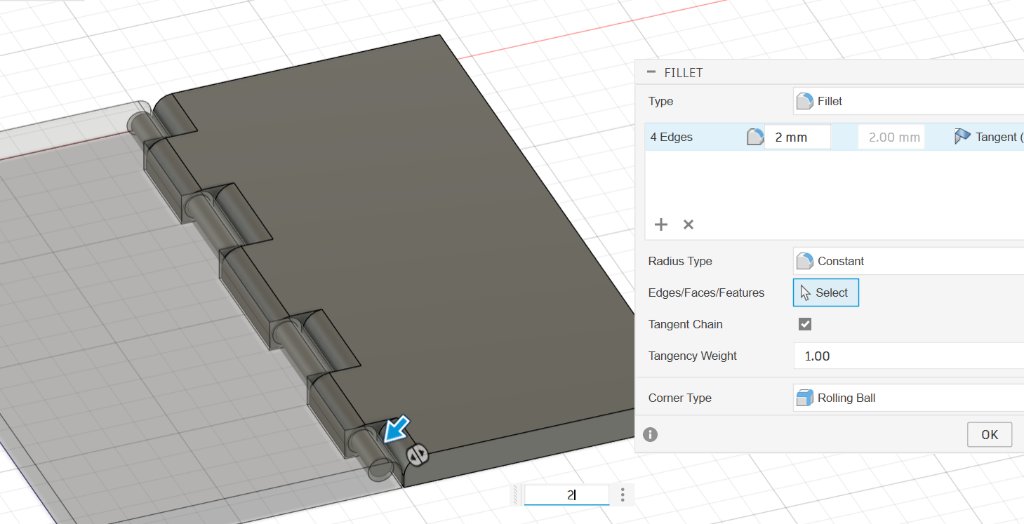
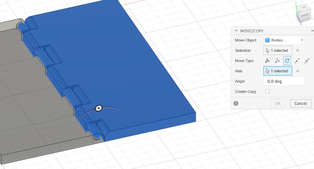
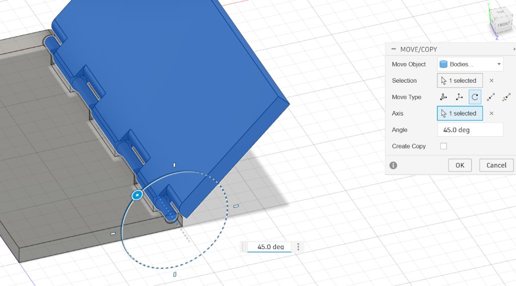
The rectangular edge would block the ratating of body 2, so I used the "Fillet" tool to fillet the edge.
I added an axis through the center of the rod.
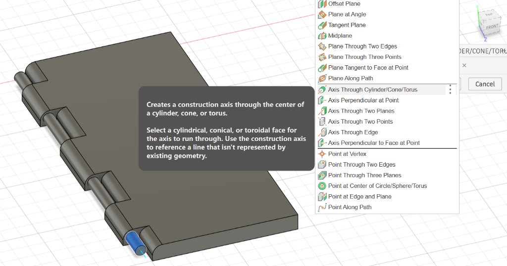
Then I used the moving tool to rotate the body 2 to check if the ratating is smooth.
At the end, I exported the model as a STL file.
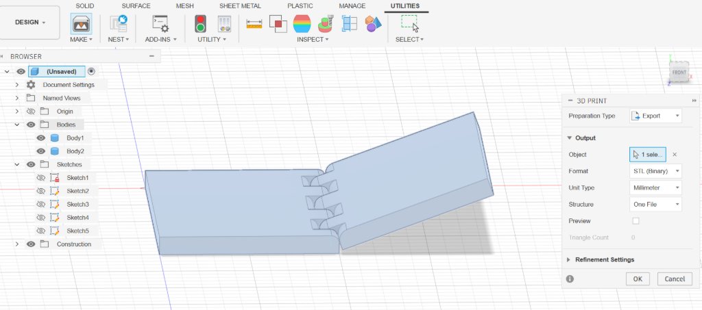
Here is the file: Rotary.stl