Week 3 — Group Assignment: Laser Cutter Tolerance Test
Chaihuo Lab
This page documents our Week 3 group collaboration to measure the laser cutter tolerances at the lab.
- Machine: SMDX
- Material: 3 mm plywood
Results
- Positive features (material to be preserved): actual width = design width − 0.1 mm → design compensation: +0.1 mm
- Negative features (slots/grooves to be cut): actual width = design width + 0.1 mm → design compensation: −0.1 mm
Process photos
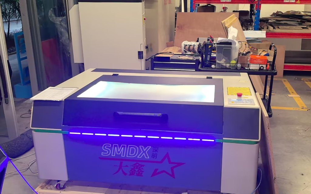
Figure 1: The laser cutter at Chaihuo; the machine is branded SMDX.
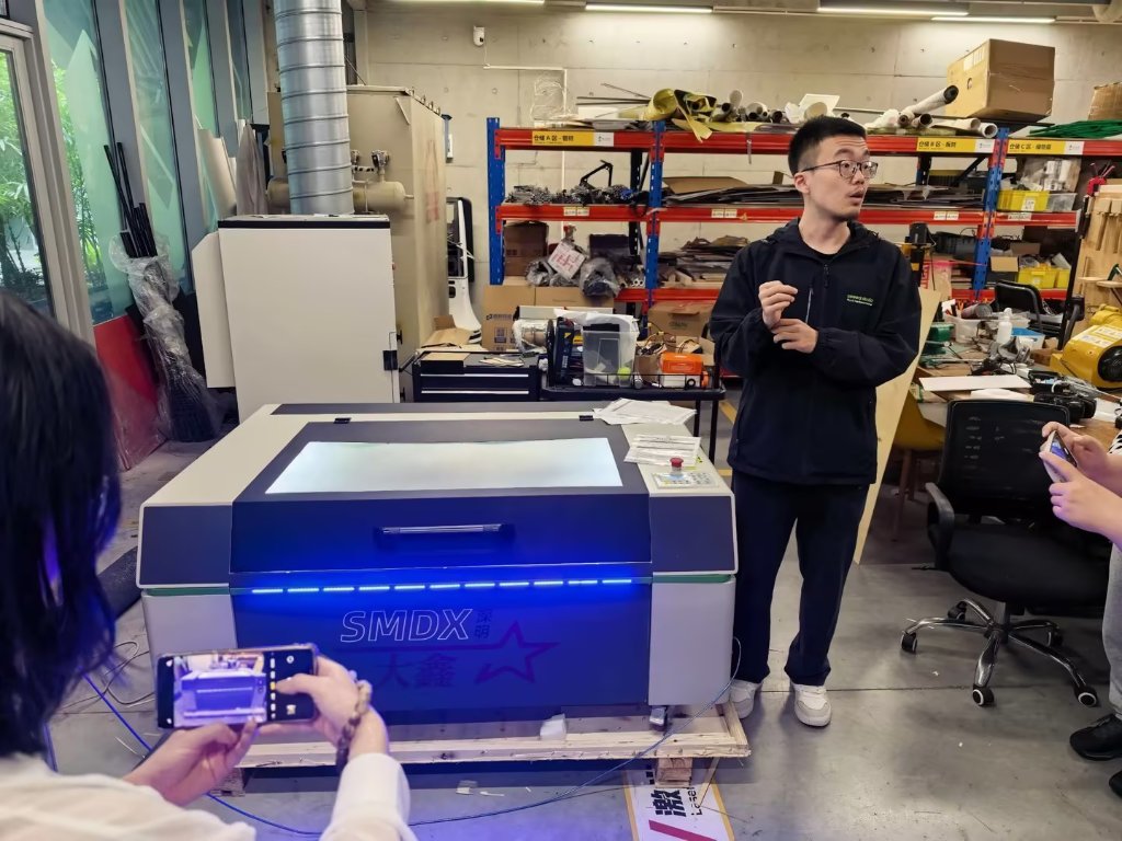
Figure 2: Our instructor introduced the laser cutter, explained how to operate it safely, and showed us how to use the control software RDWorks V8.
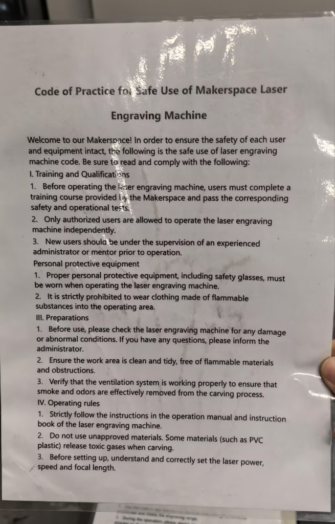
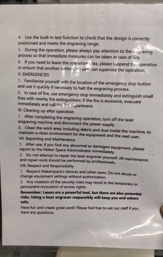
Figure 3: Printed safety instructions are posted next to the machine. Everyone should read and follow them before use. The cutting area is covered by a lid to reduce exposure to the beam.
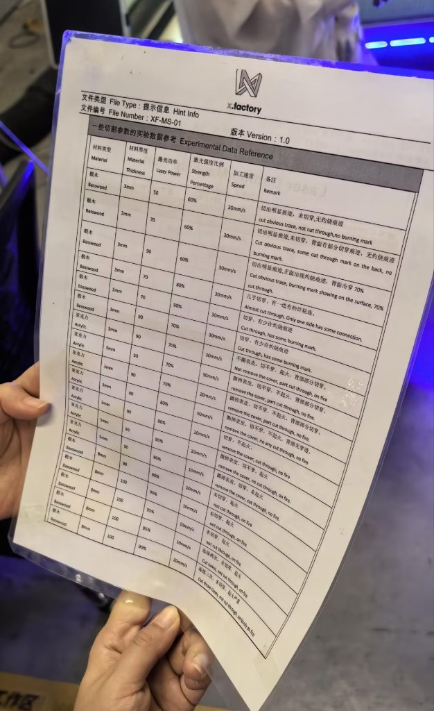
Figure 4: Suggested settings for the laser cutter. Cutting speed and laser power are the main parameters we can adjust. For different materials and thicknesses, we use different speed and power values; fine-tuning is done in the software.
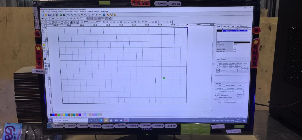
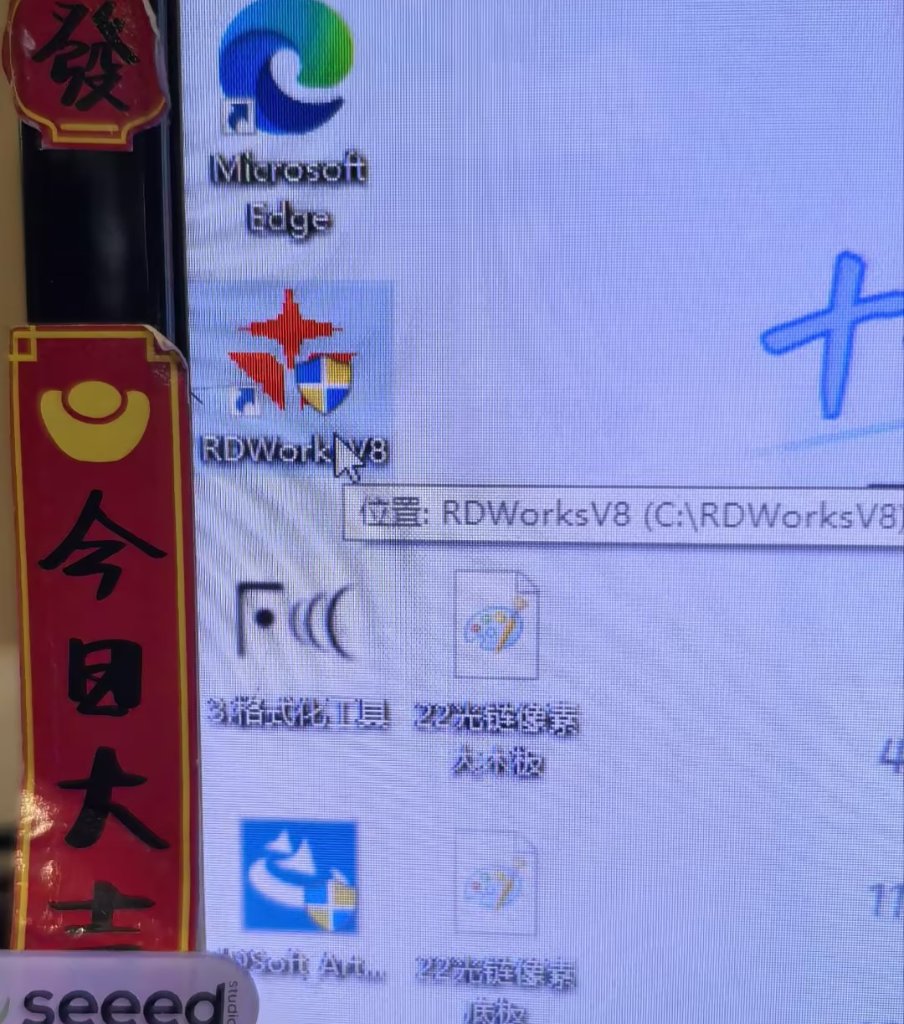
Figure 5: The design is prepared and sent to the machine from a PC running RDWorks V8.
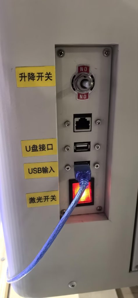
Figure 6: The laser power switch is separate from the main controls and mounted on the side of the machine. Some of us forgot to turn the laser on; the job started, but nothing happened to the plywood until the switch was enabled.
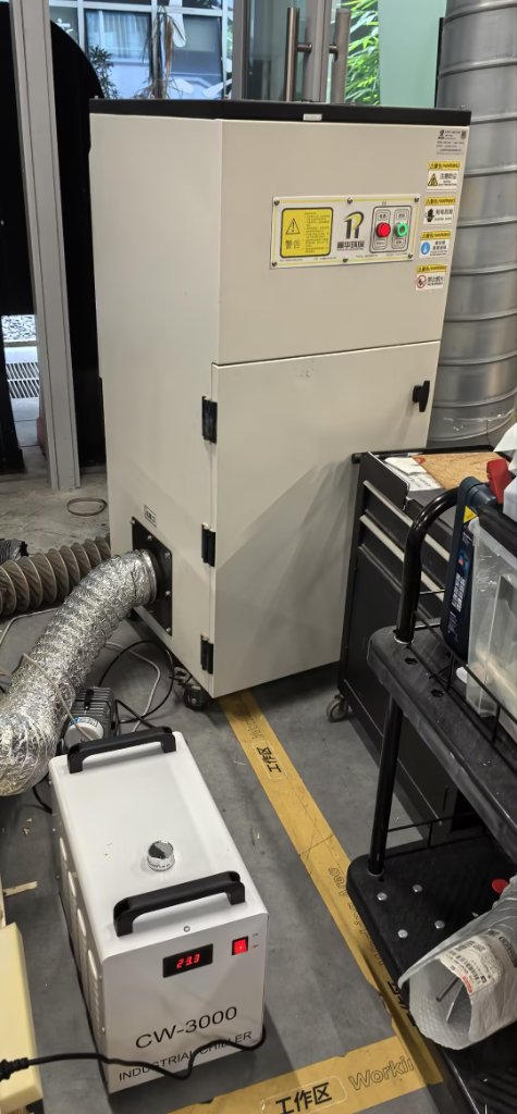
Figure 7: The cooler and air purifier must be turned on manually. The purifier did not work very well that day, so there was still a strong smell; we opened the door to ventilate the space.
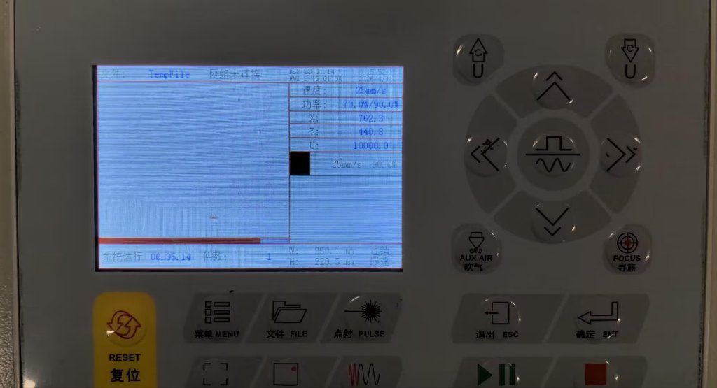
Figure 8: Control panel on the machine for adjusting settings and moving the laser head. Before cutting, we set the work origin (zero). We usually run "go scale" first; if the layout does not fit the material, we either move the sheet or set new X–Y zeroes.
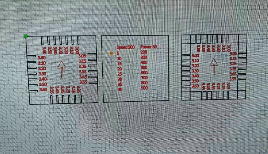
Figure 9: Designing the tolerance test pattern in Laser Maker, an easy-to-use laser design program.
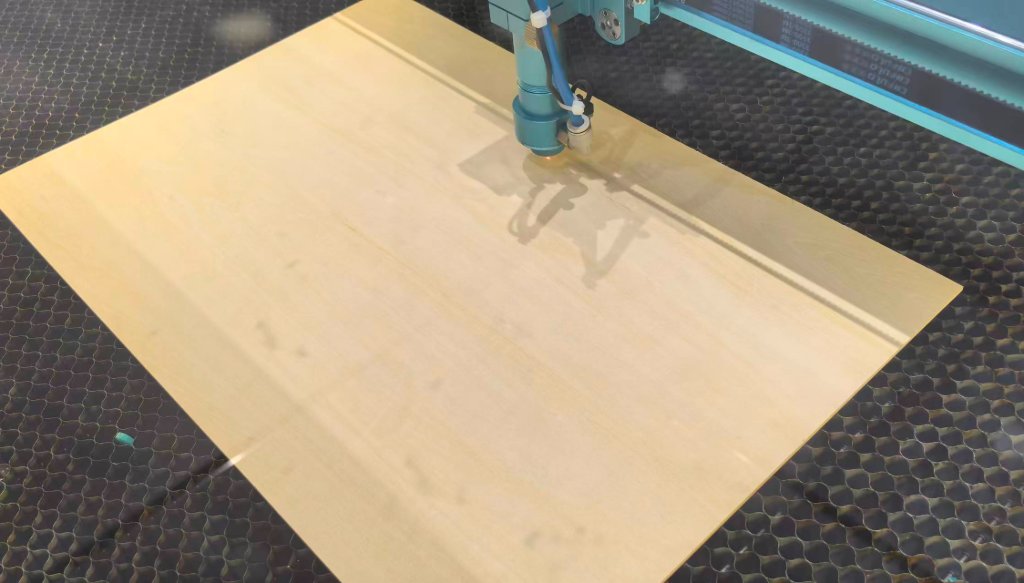
Figure 10: Cutting the 3 mm plywood.
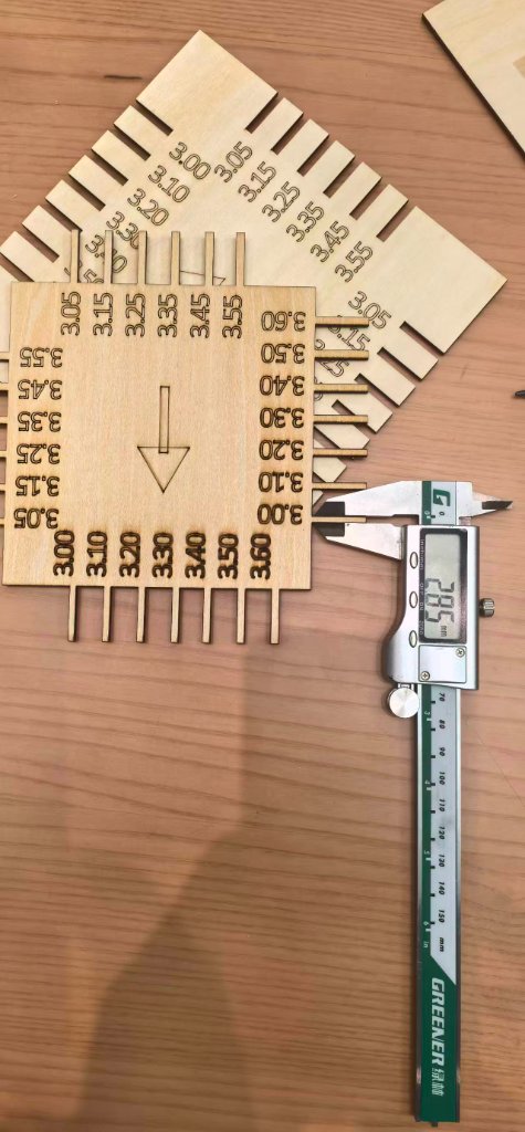
Figure 11: Measuring cut features with a caliper.
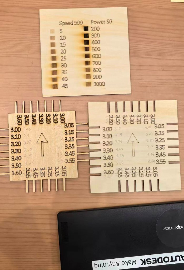
Figure 12: Summary of the tolerance measurements.
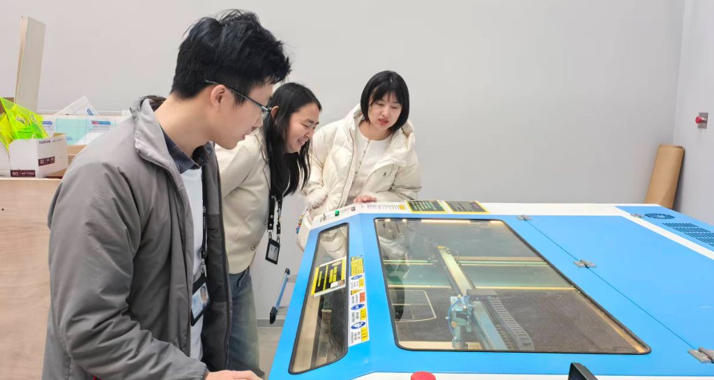
Figure 13: The group observing the machine and recording notes during the test.
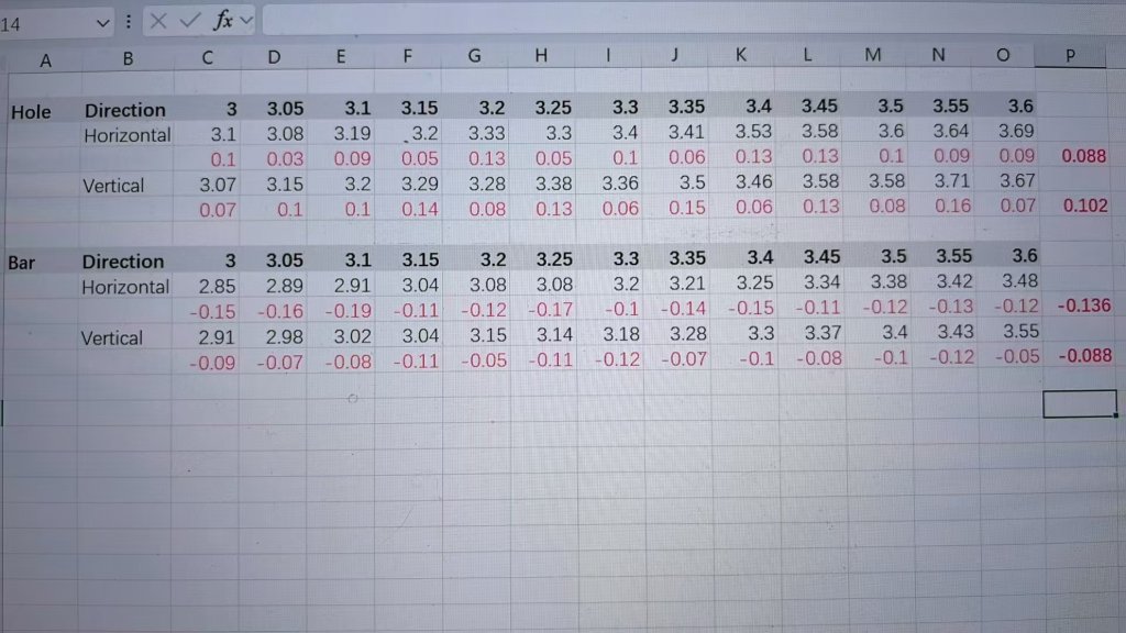
Figure 14: Recorded data from the tolerance experiment.
Beijing Lab
Group members: Guannan He, Maggie Zhang, Jenny Zhang
- Machine: Thunder Laser Nova 51
- Testing date: Feb 05, 2026
- Material: 3 mm plywood
Results
- Positive features (material to be preserved): actual width = design width − 0.1 mm → design compensation: +0.1 mm
- Negative features (slots/grooves to be cut): actual width = design width + 0.1 mm → design compensation: −0.1 mm
Testing Photos
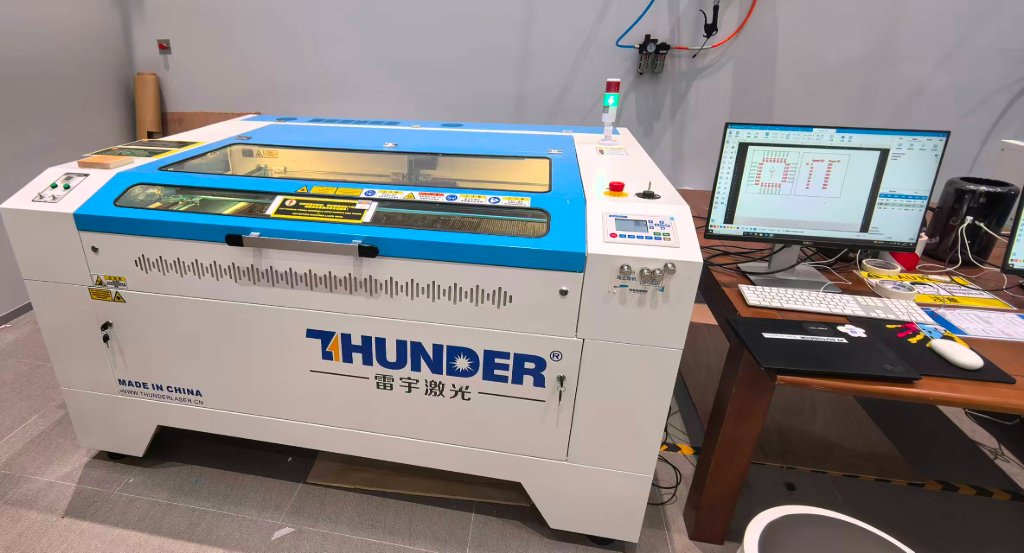
Figure 1: Thunder Laser Nova 51
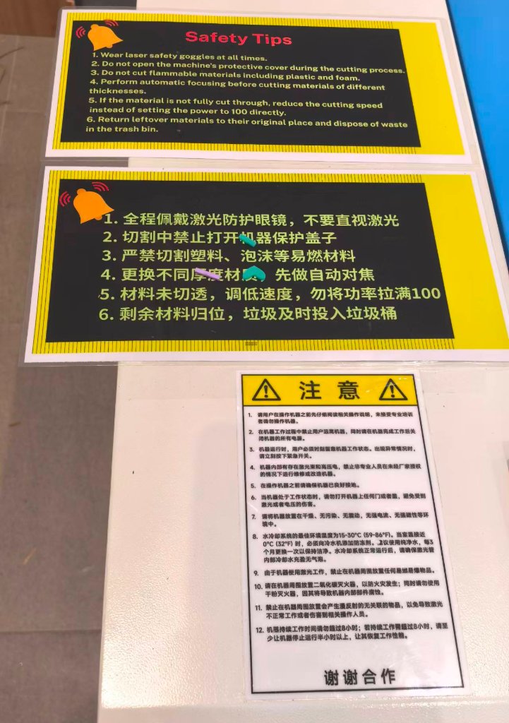
Figure 2: Thunder Laser Safety Warning
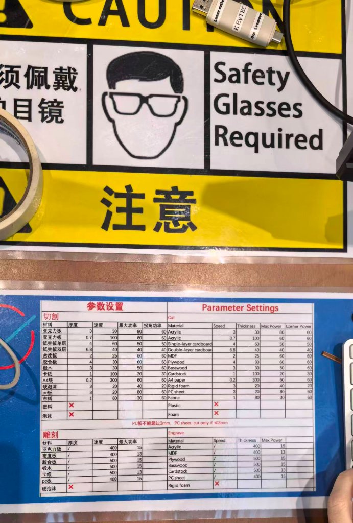
Figure 3: Thunder Laser Nova 51 Suggested Settings
Figure 4: Designing the pattern for tolerance measurement
Figure 5: Thunder Laser was cutting the plywood
Figure 6: Measuring with caliper
Figure 7: Tolerance measuring results
Figure 8: Data Analysis
Figure 9: Data