Group Assignment - CNC
The group assignment this week asked us to characterize our CNC machine: test its real cutting behavior, measure the kerf, find working feeds and speeds, and figure out what tolerances are needed for parts that press-fit together. It is the kind of exercise that sounds simple but ends up teaching you a lot about the difference between what you designed and what the machine actually cuts.
Before we could touch the machine, we went through safety training. Then we set up the machine together, ran a series of test cuts with different parameters, measured the results, and drew some practical conclusions. Everything we learned fed directly into the individual assignments.
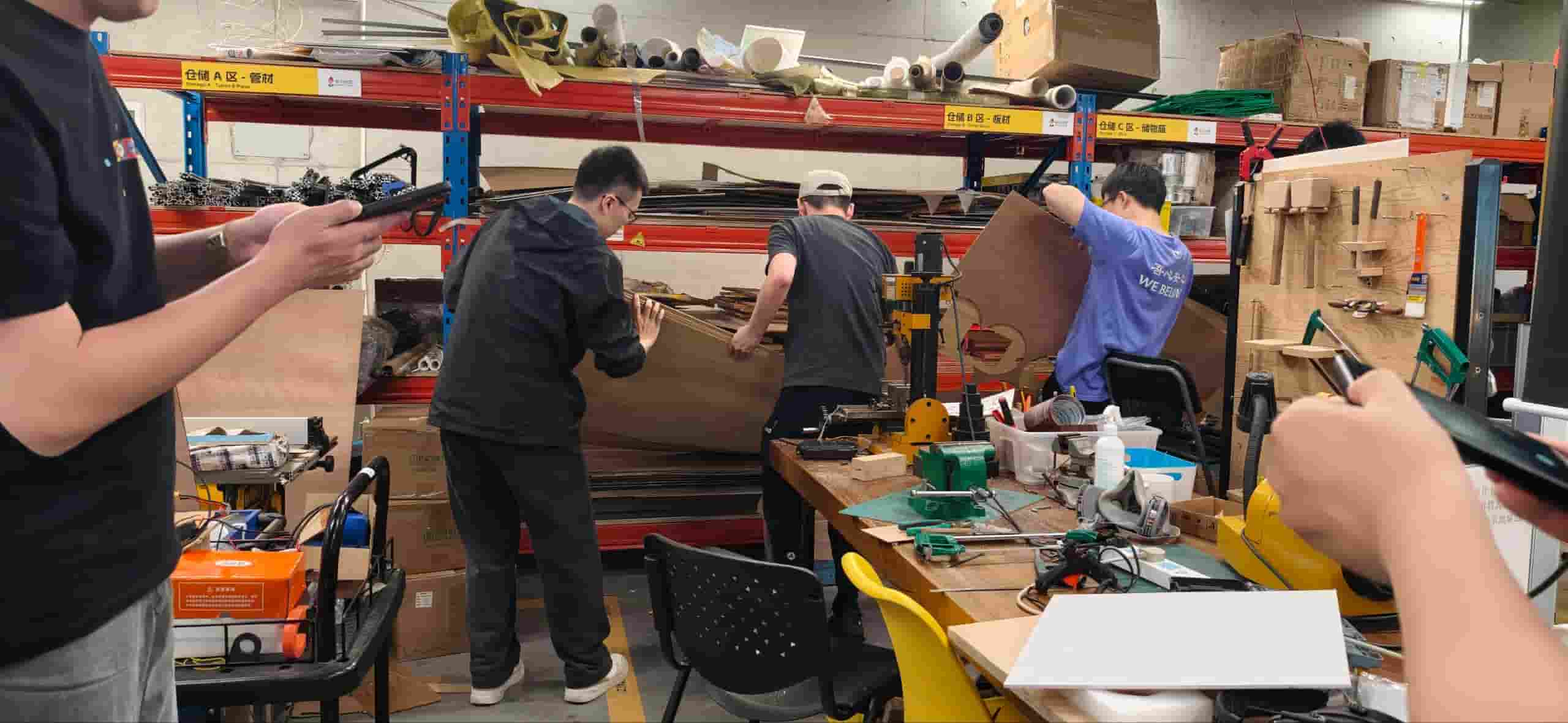
Group Members

Safety Training
We did not skip the safety training even though some of us had seen a CNC machine before. The instructor walked us through the rules properly before anyone touched the machine.
A few points that stood out:
- No loose clothing or gloves near the spindle. The bit rotates at thousands of RPM and anything dangling nearby is a real risk.
- No hands on the table during operation. Even pausing does not mean the spindle stopped instantly.
- Know the emergency stop location before you do anything else. On our machine, the emergency stop is [describe location — e.g., right side of the control cabinet]. Everyone in the group confirmed they could find it without looking.
- Dust and noise protection: CNC cutting generates a lot of fine sawdust, especially with MDF or HDF. We wore masks and noise-cancelling headphones during cutting. The dust collector was running the whole time.
- Board must be fully secured before the job starts. Any movement of the workpiece mid-cut means a ruined part at best and a broken bit or flying piece at worst.
- Check the bit before running. Look for any chipping or wobble. A damaged bit does not just cut poorly — it can break under load.
The safety rules sound like common sense when you read them on paper, but standing next to a machine that size, it feels different. It is a good reminder that big tools require actual attention, not just common caution.
Machine Introduction
Our CNC Machine
The CNC machine at our lab is Tiancheng Xinli 3STX-1325A-style.

| Specification | Details |
|---|---|
| Manufacturer | Tiancheng Xinli CNC |
| Model | 3STX-1325A |
| Working Area (X × Y) | 1300 mm × 2500 mm |
| Z-axis Travel | 180 mm |
| Spindle Speed Range | 0 – 24000 (r/pm) |
| Spindle Power | 3 kW water-cooled |
| Control File Format | G-code / UPP / nc |
| Max Feed Rate (idle) | — |
| Max Feed Rate (cutting) | 15000 mm/min |
| Positioning Accuracy | ±0.15 mm/300 mm |
Material
For characterization, we used high-density fiberboard (HDF) :
- Nominal thickness: 18 mm
- Measured actual thickness: 18.3 mm
- Board size: 1220 mm × 2440 mm
- Density: high density, heavy, dense.
We measured the actual board thickness with calipers before starting, because nominal sizes are not always accurate. The real number matters for joint design.
And the material is really heavy, we need 4 to 5 members together to carry.

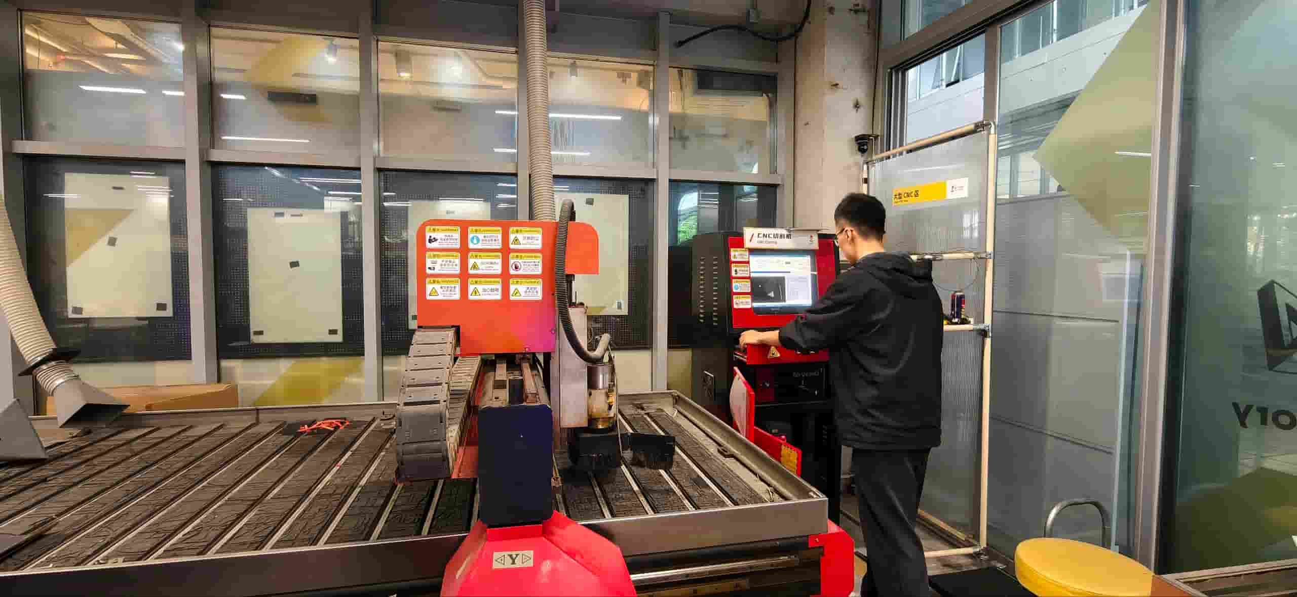
Machine Setup
Cleaning and Preparing the Table
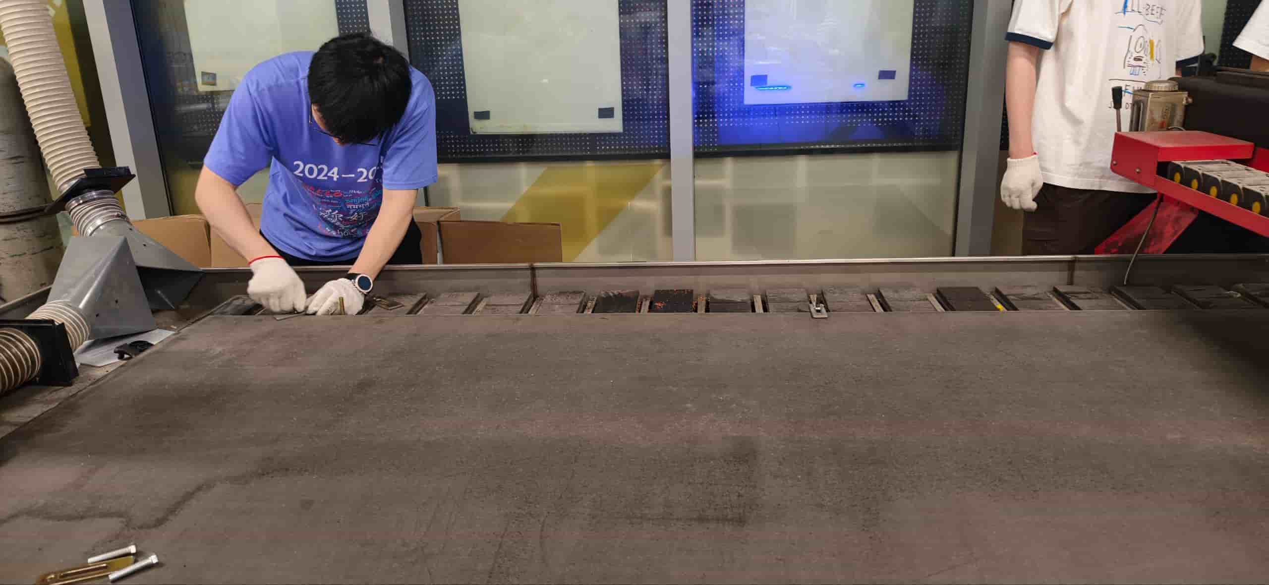
We cleaned the table before placing the board. Even small chips or debris can tilt the board and cause uneven cutting depth across the job.
Securing the Board
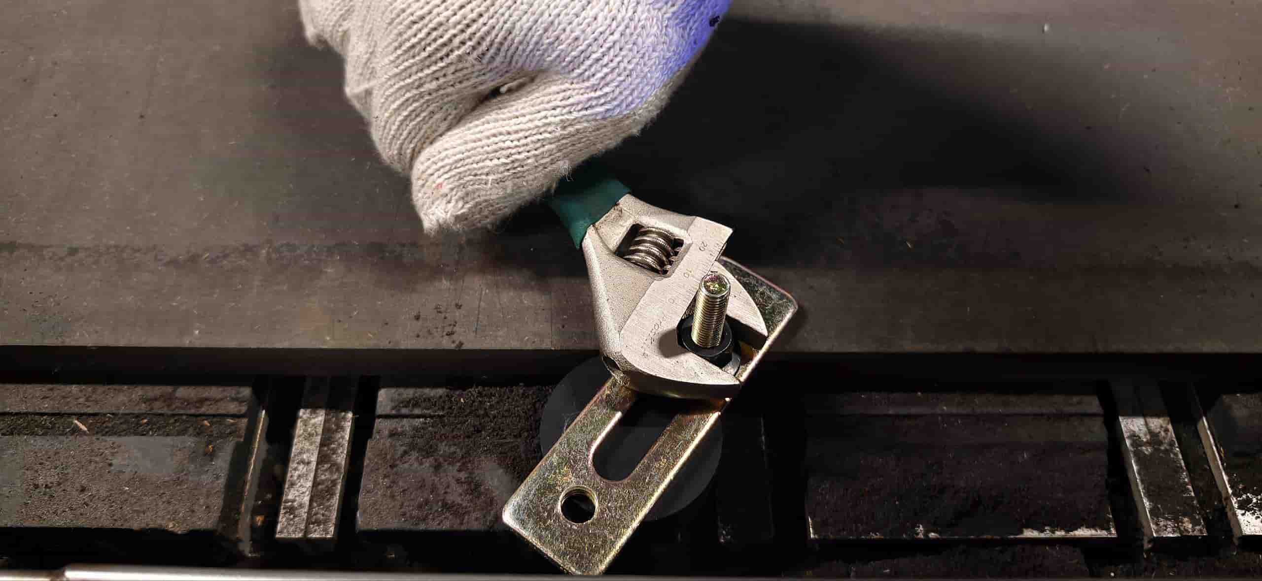
We positioned the board flat on the table and clamped it down at the edges using fasteners and screws into sacrificial layer. The important thing was to make sure the clamps did not intrude into the cutting area.
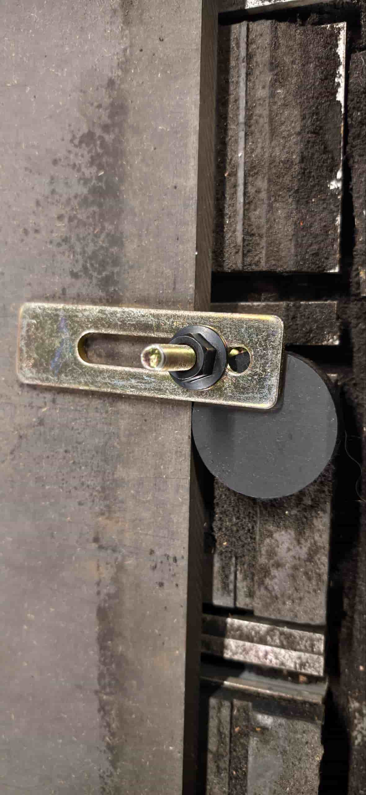
Setting the Origin (X/Y/Z Zero)
Before running any job, we set the machine's working origin. We jogged the spindle manually to the left side corner of the board and set X/Y zero there. For Z, we used the touch-off probe / we lowered the bit manually until it just touched the surface, then zeroed Z.
One thing that is easy to miss: the Z zero has to be set relative to the top surface of the board, not the machine bed. If the board is not perfectly flat or the table is not perfectly level, cuts that look uniform in the file may come out shallower on one side.
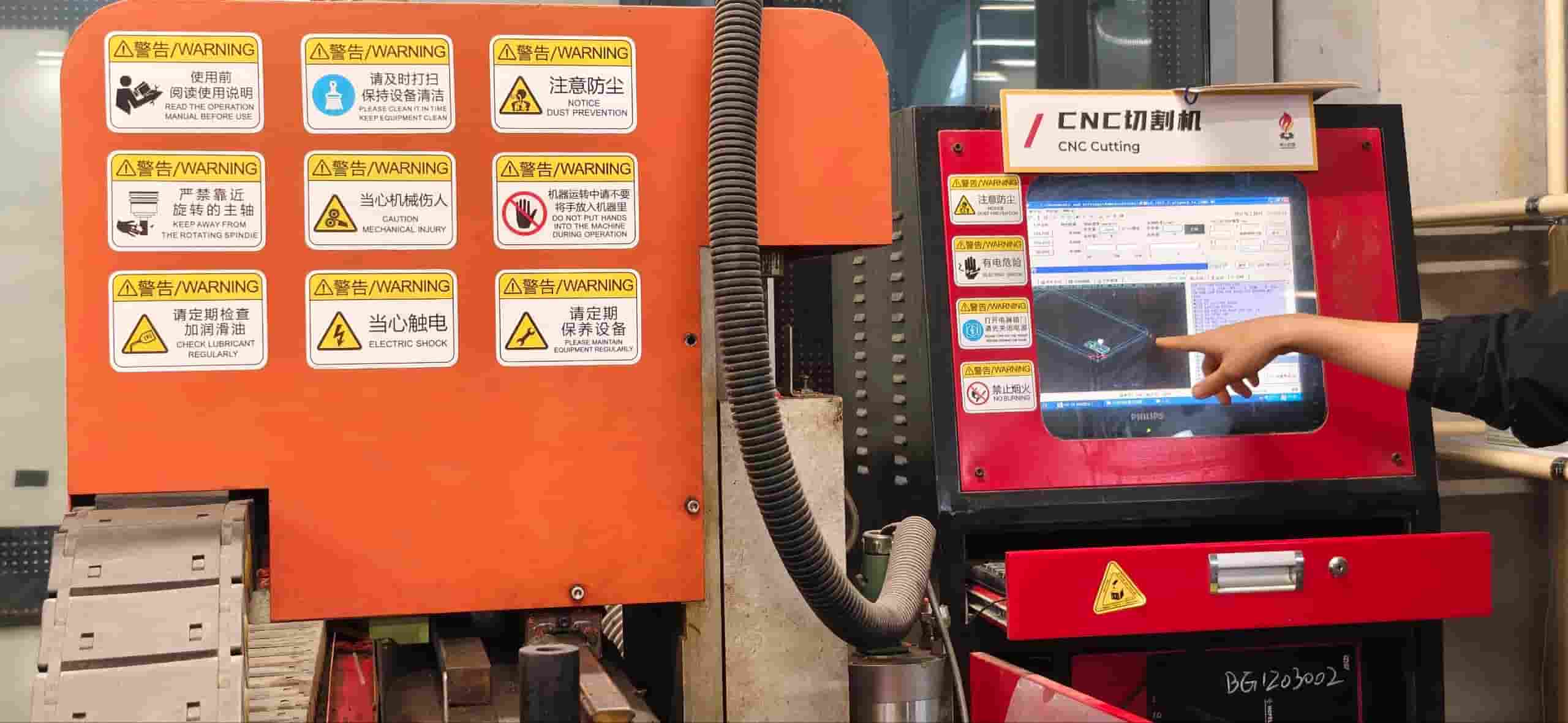
CAM Setup
Software
We used ChatGPT to convert our DXF test files into G-code.
Toolpath Settings
For contour cuts (the most common type for characterization), the key parameters we set:
| Parameter | Value Used |
|---|---|
| Toolpath type | 2D contour |
| Tool diameter | 8 mm |
| Spindle speed | 15000 rpm |
| Feed rate (cutting) | 5000 mm/min |
| Plunge rate | 1000 mm/min |
| Depth per pass | 8 mm |
| Total cut depth | full board thickness + 0.2 mm into spoilboard |
| Compensation direction | right to the left side |
Processing Order
We followed the general rule of inside before outside, small before large. Inner pockets and holes get cut first, outer contours last. The reason: once an outer contour is cut, the piece is loose and can shift. If you still have interior features to cut at that point, you lose accuracy. Cutting the inside first while the piece is still part of the larger sheet keeps everything stable.
Parameter Testing
The main goal of the group characterization was to understand how feed rate, spindle speed, and cut depth affect the quality of the cut — and to find a working combination that gives clean edges without burning, excessive tear-out, or bit breakage.
Test Design
We designed a test file with:
- A series of rectangular pockets and contour cuts to test different feed rates at fixed spindle speed
- A kerf measurement section — a known-width slot to measure actual material removed
- A set of press-fit slots with graduated tolerances to find the best fit for assembly
Tests
We fixed the spindle speed at 18000 rpm and varied the feed rate across several runs to see what changed.
The most noticeable difference was higher feed rates the edges got noticeably rougher on the exit side, and at the lowest rate there was slight discoloration suggesting heat buildup.
We also tested different depths per pass to see how aggressively we could push through the material. Cutting in multiple shallow passes takes longer but produces more consistent walls. A single full-depth pass at this board thickness put a lot of load on the bit.
For the individual assignments, we needed joints where parts slot together without glue. Getting the tolerance right matters a lot: too tight and you cannot assemble, too loose and the structure wobbles.
One important detail that came up during this test: inside corners. Because a round bit cannot cut a true 90° inside corner, any slot has rounded corners at the ends. If a mating piece has a square corner, it will hit those rounded corners and not seat fully. The solution is either to add a small dog-bone relief at each inside corner in the design, or to extend the slot slightly at each end.
Summary of Recommended Parameters
After all the tests, these are the settings we found to work well for HDF/MDF with our machine and tool:
| Parameter | Recommended Value |
|---|---|
| Material | HDF / MDF, ~18.7 mm |
| Bit diameter | 6 mm flat end mill |
| Spindle speed | 24000 rpm |
| Feed rate | 2000 mm/min |
| Plunge rate | 1000 mm/min |
| Depth per pass | 6 mm |
| Tabs | 3 mm tall, 5 mm wide, placed at corners |
| Press-fit slot offset | −0.4 mm per side vs. measured board thickness |
| Kerf (average) | ~0.4 mm |
| Dog-bone radius | bit radius = 3 mm |
What We Learned
The whole point of this exercise is to stop guessing and start knowing the machine's actual behavior. A few things I will carry forward into my individual project:
- Measure the real board thickness. Nominal 18 mm is rarely 18.0 mm. This week ours was 18.3 mm (+0.3 mm over nominal). If you design joints based on the label instead of the caliper, they will not fit.
- Kerf compensation has to be built into the design. The machine removes more material than the bit diameter suggests. For slots that need to receive a board, add half the kerf to each side.
- Inside corners always need attention. A round bit leaves a round corner. Design your joints around that, or plan for dog-bones.
- Feed rate affects more than just speed. Going too slow caused slight burning at corners in our low-feed tests. Going too fast gave rougher edges. There is a range in the middle that works well — find it for your specific material and bit before cutting the final piece.
- Cut order matters. Inside before outside. Small before large. It is a small rule that prevents a lot of frustration.
- Secure the board properly before you start. An unsecured board that shifts mid-cut can ruin the whole job and is also a safety issue.
This group characterization made me much more confident going into the individual assignment. The numbers in the recommended parameters table above are not arbitrary — they came from actual cuts, measurements, and at least a few mistakes. That is the kind of reference I actually trust.