Week11 - Networking and Communications
Background Learning – How Devices Communicate
Before this assignment, I always thought “communication” between devices was something abstract, like WiFi just magically sends data from one place to another. But after building a simple setup with two microcontrollers, I started to understand what’s really happening underneath.
At a very basic level, communication is just about turning data into something that can travel, and then turning it back into data again.
For example, when a sensor reads a temperature like 25°C, the device doesn’t actually send “25” directly. Instead, it converts this number into binary (a series of 0s and 1s), and then into signals. These signals can be electrical (through wires) or wireless (through the air).
In wireless communication like WiFi or Bluetooth, the data is sent using radio waves. What surprised me is that devices are not sending “numbers” through the air, but patterns of electromagnetic signals. These patterns represent the binary data. The sender encodes the data into these signals, and the receiver captures them and decodes them back into meaningful values.
Another thing I realized is that communication is not just about sending signals, but also about agreeing on how to understand them. This is where protocols come in. Even in my simple project, I had to define what kind of data I was sending (for example, temperature values in a certain format), so the receiving device could correctly interpret it.
In my project, the communication happens directly between two devices, without using the internet or any cloud service. This helped me see a simpler version of IoT systems. Instead of sending data to a dashboard, I could observe the data directly through the serial monitor. It made the whole process more transparent and easier to understand.
Overall, this assignment helped me realize that IoT communication is not something “invisible” or complicated by default, it is essentially a process of encoding, transmitting, and decoding information using physical signals, following a shared set of rules.
Thanks for ChatGPT explained the clear logic to me.
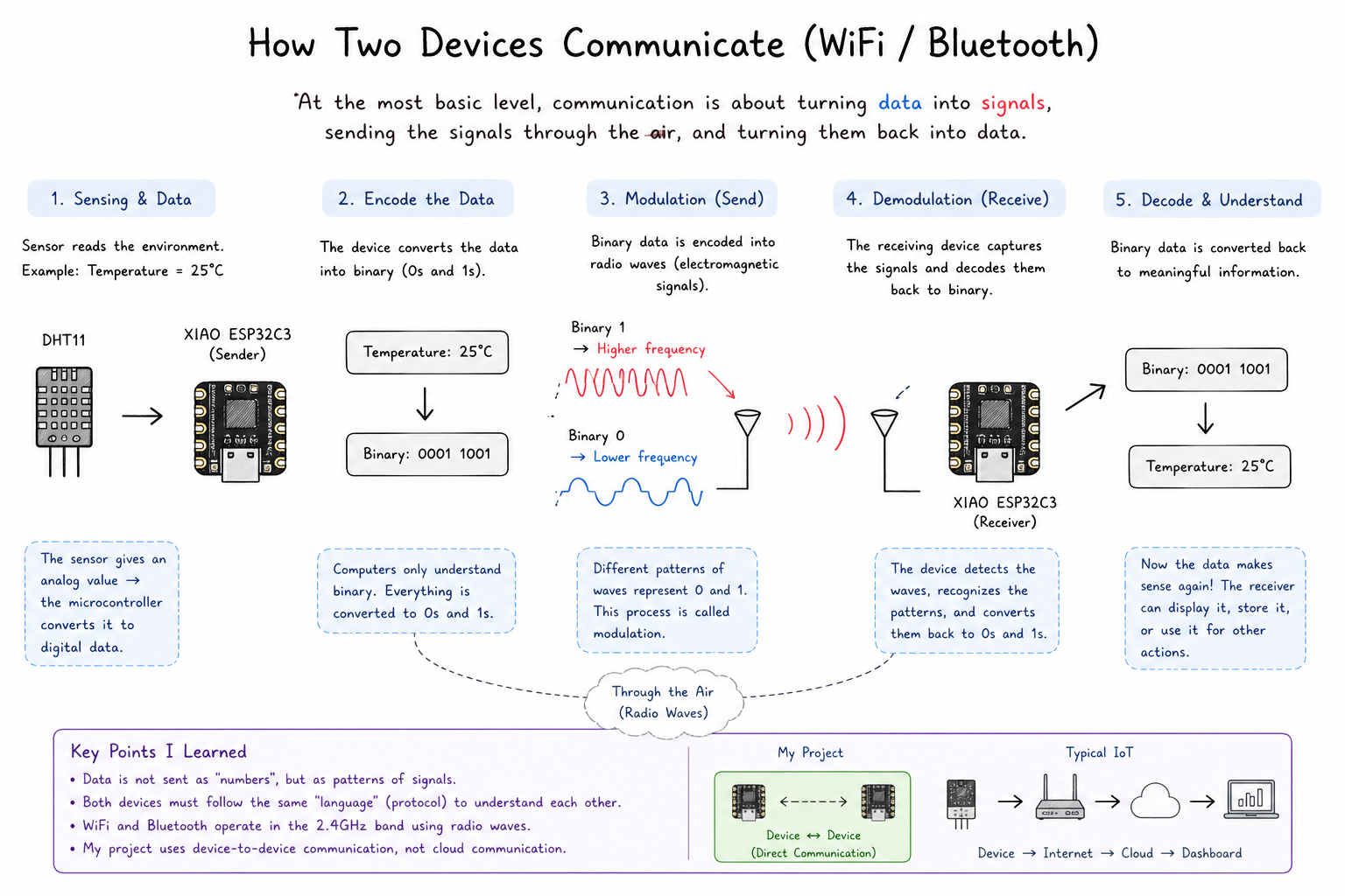
Visual summary of encoding, transmission over the air, decoding, and how this project compares to a typical cloud IoT setup.
Individual Assignment
Build a simple networked system where two devices can communicate with each other, one sending data, the other receiving it.
Overview
I built a networked system using two XIAO ESP32C3 boards communicating over Wi-Fi. The first board acts as a server: it reads temperature data from a DHT11 sensor and exposes that data through a tiny HTTP endpoint it hosts itself. The second board acts as a client: every 5 seconds, it sends an HTTP GET request to the server and prints whatever it gets back to the serial monitor.
The communication model is a classic request–response pattern, the client asks, the server answers, which is exactly how a web browser and a web server work, just running on two $5 microcontrollers sitting on my desk.
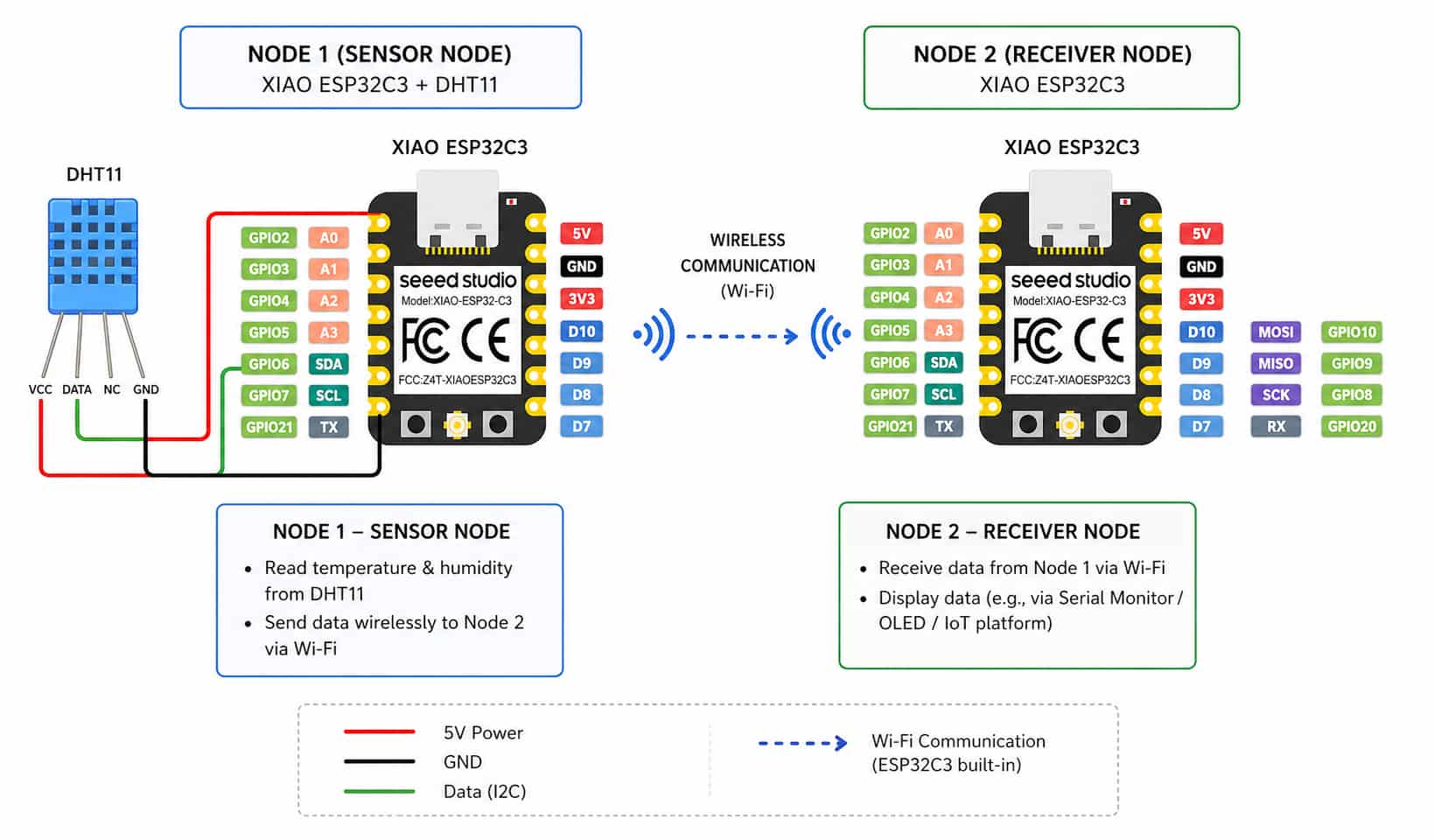
Downloadable sketches
These are the same programs described on this page (paths are relative to the repository root; on GitLab, open the file and use Raw or Download):
- Wi-Fi connect test (minimal)
- HTTP server + DHT11 (
/temperatureendpoint) - HTTP client (polls the server)
Why HTTP Over Wi-Fi?
Before I jumped into code, I thought about what kind of communication protocol would make sense for this task. The ESP32C3 has a built-in 2.4 GHz Wi-Fi radio, so Wi-Fi was an obvious choice for the transport layer. For the application protocol sitting on top, I chose HTTP for a few practical reasons:
- The Arduino ESP32 library ships with both a WebServer class and an HTTPClient class, so I didn't need to write raw socket code.
- HTTP is text-based and easy to inspect, you can literally type the server's URL into a browser and see whether it's working.
- The request–response model maps cleanly onto a polling use case: the client asks for data when it needs it, the server answers.
The alternative would have been something like MQTT (a lightweight publish–subscribe protocol popular in IoT), but that requires a separate broker server to sit in the middle. HTTP with two boards and no broker felt like the right level of complexity to actually understand what's happening.
Hardware
Components
| Component | Quantity | Notes |
|---|---|---|
| XIAO ESP32C3 | 2 | One server, one client |
| Grove DHT11 temperature & humidity sensor | 1 | Connected to the server board |
| USB-C cable | 2 | For power and programming |
| Jumper wires | 3 | To wire DHT11 to XIAO |
Wiring the DHT11 to the Server Board
The DHT11 is a single-bus digital sensor, it sends all its data (temperature + humidity) over one signal wire. I connected it to pin D2 on the first XIAO:
| DHT11 Pin | XIAO ESP32C3 Pin |
|---|---|
| VCC | 5V |
| GND | GND |
| DATA | D2 |
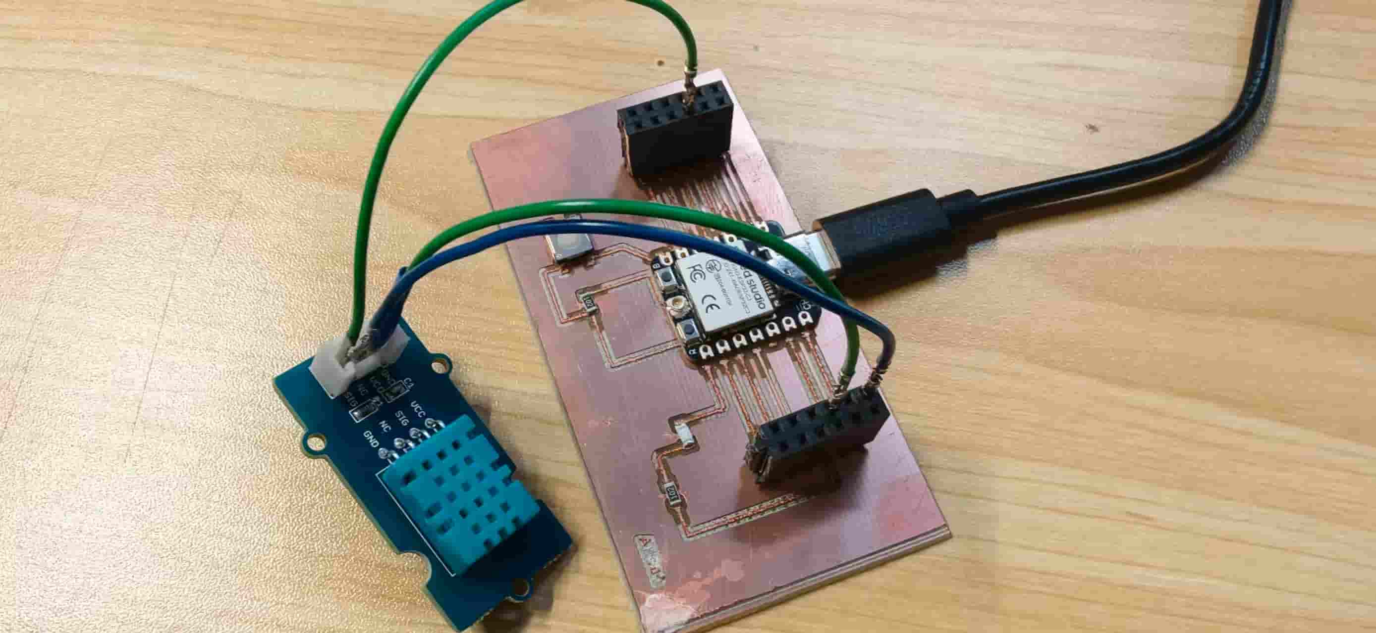
One thing worth noting: the Grove DHT11 module already has a pull-up resistor built into the PCB, so I didn't need to add an external one. If you're using a bare DHT11 chip, you need a 4.7 kΩ or 10 kΩ resistor between DATA and VCC, without it the signal line floats and you get garbage readings or nothing at all.
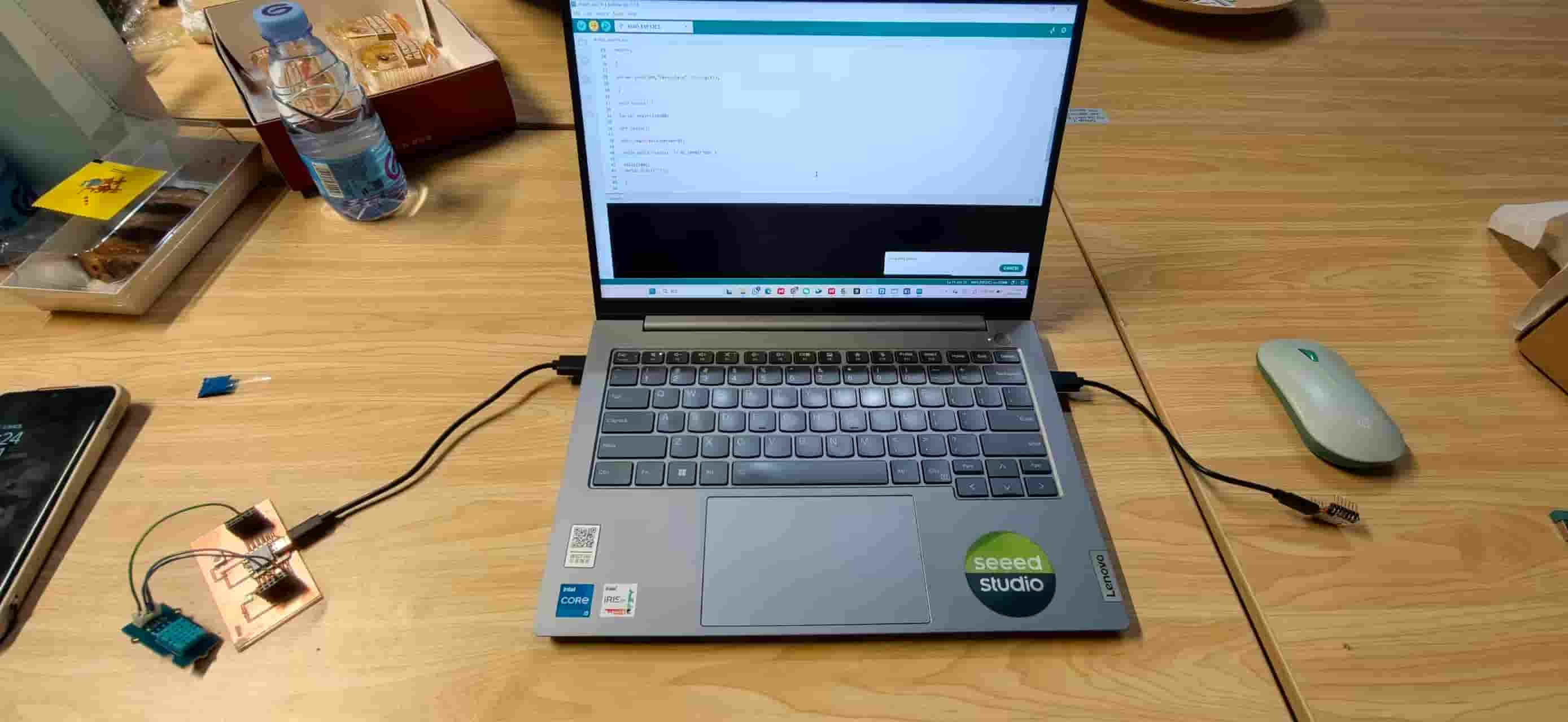
Library Setup
Before anything compiles, you need the right libraries installed in Arduino IDE.
For the server board
- DHT sensor library by Adafruit. Handles the one-wire timing protocol for reading from the DHT11.
- Adafruit Unified Sensor — a dependency that the DHT library requires.
- WiFi and WebServer — these ship with the ESP32 Arduino core, so if you've already added the Seeed ESP32 board package, they're already available. No separate install needed.
To install DHT support: go to Tools → Manage Libraries, search for DHT sensor library, and install the Adafruit version. When it asks whether to also install dependencies, click Install All that gets you Adafruit Unified Sensor automatically.
For the client board
Only WiFi and HTTPClient both come with the ESP32 Arduino core. Nothing extra to install.
Board settings (both boards)
- Tools → Board → Seeed Studio XIAO Series → Seeed Studio XIAO ESP32C3
- Tools → Port → select the COM port that appears when you plug in the board
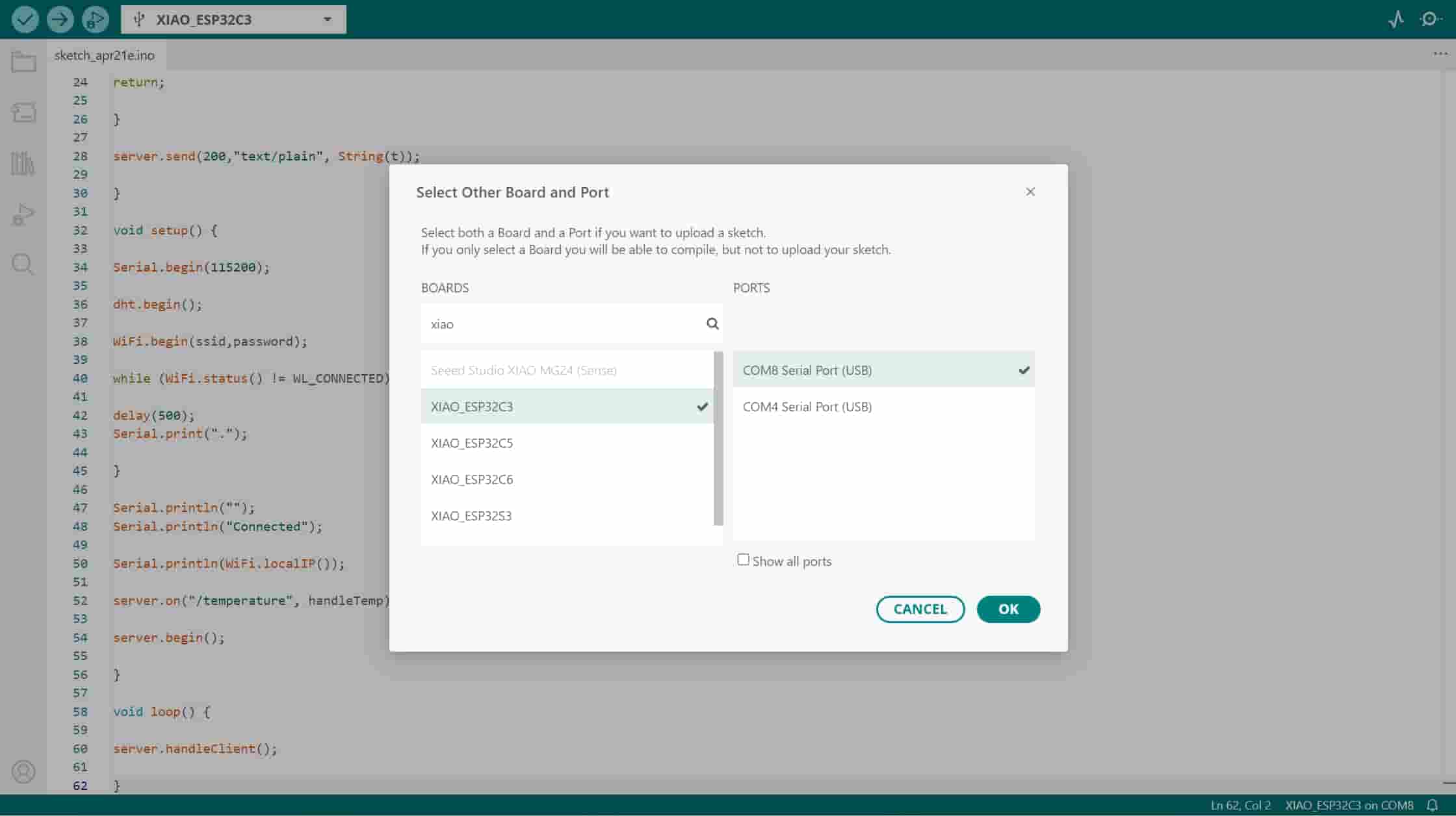
In Arduino IDE 2, you can confirm board and COM port in one place: Board and port in the toolbar → Select Other Board and Port, filter for XIAO, then pick the serial device that appears when you plug in USB.
Step 1 — Confirm Both Boards Can Connect to Wi-Fi
Before writing any server or sensor code, I wanted to prove that both boards could actually reach the same Wi-Fi network. I flashed this minimal test sketch to each board one at a time:
#include <WiFi.h>

const char* ssid     = "X.factory2.4G";
const char* password = "make0314";

void setup() {
  Serial.begin(115200);
  WiFi.begin(ssid, password);

  Serial.print("Connecting");
  while (WiFi.status() != WL_CONNECTED) {
    delay(500);
    Serial.print(".");
  }

  Serial.println("");
  Serial.println("Connected!");
  Serial.println(WiFi.localIP());
}

void loop() {}
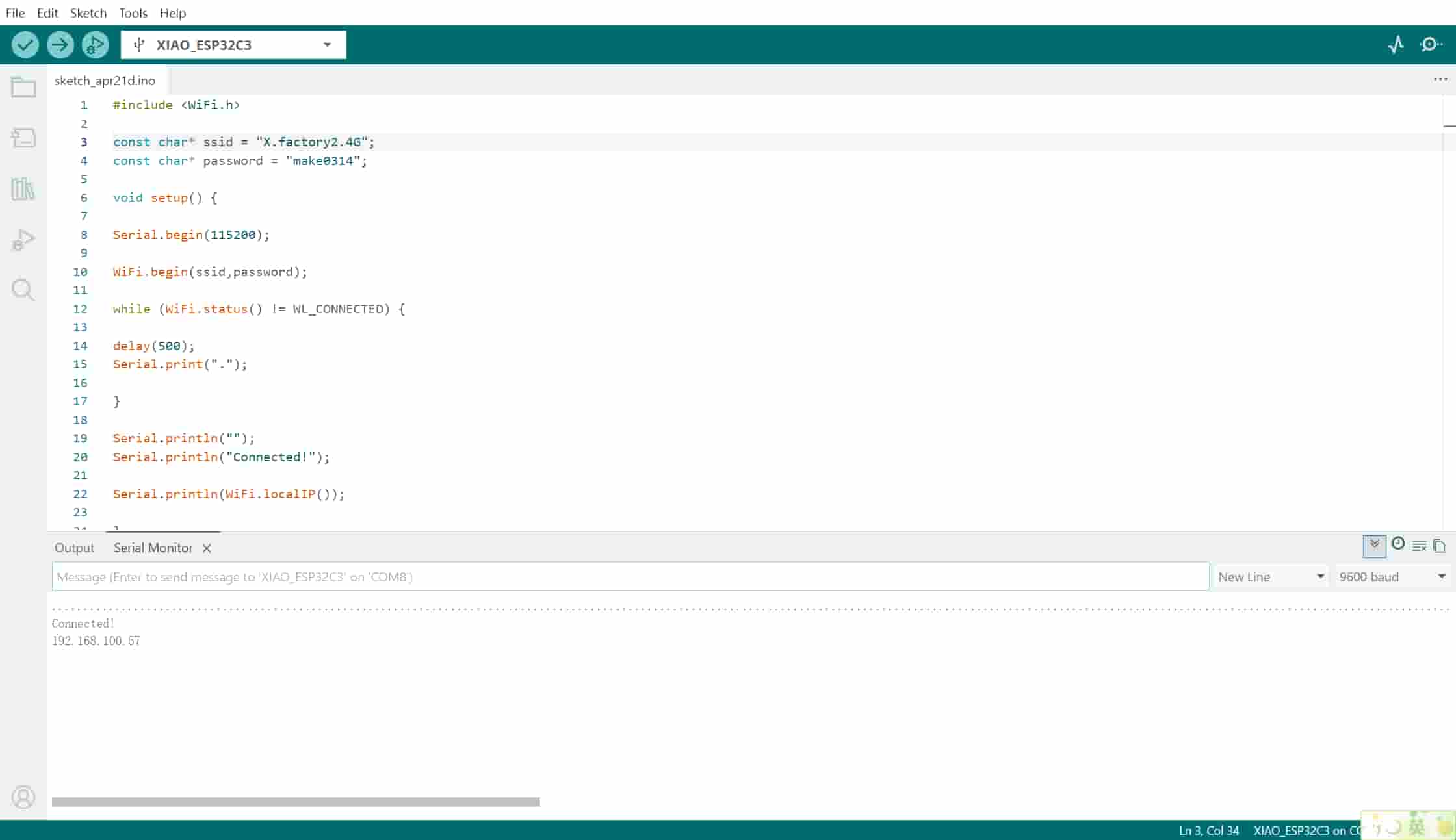
What this code does: WiFi.begin() kicks off the association process — the ESP32C3 sends probe frames, authenticates with the access point, and requests a DHCP lease. The while loop just waits and prints dots until WiFi.status() returns WL_CONNECTED. Once connected, WiFi.localIP() returns the IP address the DHCP server assigned to the board.
First board output:
Connecting......
Connected!
192.168.100.98
Second board output:
Connecting......
Connected!
192.168.100.94
Both boards on the same subnet. Good.
Screenshot from the same Wi-Fi test sketch: connected, with the board’s DHCP address printed in the Serial Monitor (your IP will differ depending on the network and lease).
Troubleshooting: The 5 GHz Problem
The day before this worked, I had spent an embarrassing amount of time debugging a "connection" that was never going to succeed. The dots just kept printing. No Connected!, no IP.
I checked the password three times. I re-flashed the firmware. I switched USB cables.
Eventually I looked at what network the boards were actually trying to join. Our lab has both a 2.4 GHz and a 5 GHz network — same name root, different bands. I had been pointing the boards at the 5 GHz one.
The ESP32C3's Wi-Fi radio only supports 802.11b/g/n at 2.4 GHz. It has no 5 GHz hardware at all. If you give it a 5 GHz SSID, it just can't see the access point — no error message, no useful feedback, just an endless connection loop.
The fix was switching the SSID in the code to the 2.4 GHz network (X.factory2.4G instead of X.factory5G). Both boards connected immediately after that. The lesson: always check your band before blaming your code.
Step 2 — Build the Temperature Server
With Wi-Fi working, I focused on the first board. The goal was to turn it into a device that:
- Reads temperature from the DHT11
- Runs an HTTP server
- Serves that temperature as plain text at the path
/temperature
Here's the full server code:
#include <WiFi.h>
#include <WebServer.h>
#include "DHT.h"

#define DHTPIN   D2
#define DHTTYPE  DHT11

DHT dht(DHTPIN, DHTTYPE);

const char* ssid     = "X.factory2.4G";
const char* password = "make0314";

WebServer server(80);

void handleTemp() {
  float t = dht.readTemperature();
  if (isnan(t)) {
    server.send(200, "text/plain", "Sensor Error");
    return;
  }
  server.send(200, "text/plain", String(t));
}

void setup() {
  Serial.begin(115200);
  dht.begin();

  WiFi.begin(ssid, password);
  while (WiFi.status() != WL_CONNECTED) {
    delay(500);
    Serial.print(".");
  }
  Serial.println("");
  Serial.println("Connected");
  Serial.println(WiFi.localIP());

  server.on("/temperature", handleTemp);
  server.begin();
  Serial.println("HTTP server started");
}

void loop() {
  server.handleClient();
}
What each part does
WebServer server(80) — This creates an HTTP server object listening on port 80, which is the standard HTTP port. Port numbers are just labels that tell the networking stack which application should handle incoming packets. Browsers default to port 80 for http:// URLs, so you don't need to type a port number to reach it.
server.on("/temperature", handleTemp) — This registers a route. Whenever the server receives a GET request for the path /temperature, it calls the handleTemp function. Think of it as the same thing a web framework does when you write something like app.get('/temperature', handler).
handleTemp() — This is the actual request handler. It reads from the DHT11, and if the reading is valid, it sends back the temperature as a plain text HTTP response with status code 200 OK. If readTemperature() returns NaN (which happens when the sensor doesn't respond), it sends back "Sensor Error" instead of crashing.
server.handleClient() in loop() — This is the non-blocking way to run the server. Each time loop() runs, handleClient() checks whether any client has connected and, if so, dispatches the request to the right handler. The ESP32's single-core architecture means the server can only do one thing at a time, so this polling approach keeps it responsive without needing threads.
Testing the server with a browser
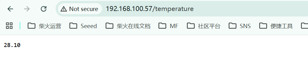
Once flashed, I opened a browser on my laptop (connected to the same network) and typed:
http://192.168.100.98/temperature
The browser showed:
27.00
Just a plain number. That confirmed the server was running and reading the sensor correctly. Being able to test a microcontroller endpoint with a browser is one of the nicest things about using HTTP, it's immediately human-inspectable.
Another run (different day / lease): the browser hitting the same /temperature path on the server’s LAN address, showing the live value as plain text.
Here is a screen recording of opening the /temperature URL in the browser and seeing the live value update:
Step 3 — Build the Client That Fetches the Data
With the server working, the second board just needed to act like a simple browser: connect to the network, make an HTTP GET request to the server's IP, and print whatever comes back.
#include <WiFi.h>
#include <HTTPClient.h>

const char* ssid     = "X.factory2.4G";
const char* password = "make0314";

String serverURL = "http://192.168.100.98/temperature";

void setup() {
  Serial.begin(115200);
  WiFi.begin(ssid, password);

  Serial.print("Connecting");
  while (WiFi.status() != WL_CONNECTED) {
    delay(500);
    Serial.print(".");
  }
  Serial.println("");
  Serial.println("Connected to WiFi");
}

void loop() {
  if (WiFi.status() == WL_CONNECTED) {
    HTTPClient http;
    http.begin(serverURL);

    int httpCode = http.GET();

    if (httpCode > 0) {
      String data = http.getString();
      Serial.println("Temperature received:");
      Serial.println(data);
    } else {
      Serial.print("Request failed, error code: ");
      Serial.println(httpCode);
    }

    http.end();
  } else {
    Serial.println("WiFi disconnected, skipping request");
  }

  delay(5000);
}
What each part does
HTTPClient http — Creates a client object that manages a single HTTP connection. It handles the TCP socket, the HTTP handshake, headers, and response parsing behind the scenes.
http.begin(serverURL) — Parses the URL and prepares the connection target. At this point nothing has been sent yet — it's just configuration.
http.GET() — Sends the actual HTTP GET request. The return value is the HTTP status code: 200 means OK, 404 means not found, any negative number means a connection-level error (the server wasn't reachable at all, not just that it returned an error response). Checking httpCode > 0 separates "the server responded with something" from "the board couldn't even reach the server."
http.getString() — Reads the response body as a String. In this case the server sends back a single number like 27.00, so this is all I need.
http.end() — Closes the connection and frees resources. Important to call this before starting the next request — skipping it causes a slow memory leak.
delay(5000) — Waits 5 seconds before the next poll. The DHT11 itself needs at least 2 seconds between readings (it's not a fast sensor), so 5 seconds gives plenty of margin.
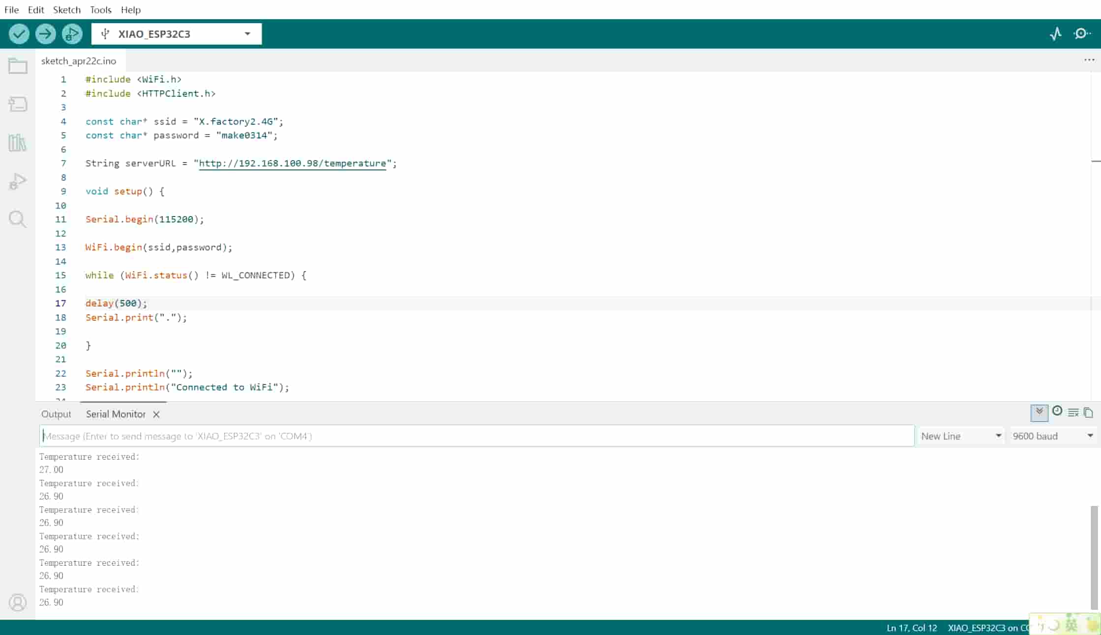
Serial monitor output
Once uploaded, the second board connected and started polling:
Connecting......
Connected to WiFi
Temperature received:
27.00
Temperature received:
27.00
Temperature received:
28.00
The temperature was updating every 5 seconds. The two boards were genuinely talking to each other — one reading a physical sensor, one fetching that reading over the network.
In the IDE, the client sketch (Wi-Fi + HTTPClient) printing Temperature received: and the values matches what I saw in the browser on the server.
Step 4 — Verifying the Full System
To confirm the whole thing was working end-to-end, I ran the following checks:
Check 1: Browser test on the server endpoint
While the client was running, I also had the browser open at http://192.168.100.98/temperature. The value in the browser and the value printing on the client's serial monitor were always the same. That meant the server wasn't serving stale or cached data — it was reading the sensor fresh on every request.
Check 2: What happens when the server is powered off I unplugged the server board mid-run. On the client, the next poll attempt printed:
Request failed, error code: -1
Then the attempts after that also failed, and when I plugged the server back in, the client automatically recovered and started printing temperature values again — no manual reset needed on either side. The WiFi.status() == WL_CONNECTED check in loop() skips the HTTP request entirely if Wi-Fi drops, and http.GET() returns an error code rather than crashing if the server is unreachable. Graceful failure matters.
Check 3: Temperature sanity check The lab was at roughly 27–28°C, which matched what both the browser and the client serial monitor showed. I breathed on the sensor briefly and watched the value climb to 29°C and then drift back down. The sensor was actually sensing.
How the HTTP Request–Response Cycle Works
Under the hood, every time the client makes a request, this is what's happening over the network:
- Client opens a TCP connection to
192.168.100.98on port80. - Client sends an HTTP GET request:
GET /temperature HTTP/1.1
Host: 192.168.100.98 - Server reads the DHT11, formats the temperature as a string, and sends back an HTTP response:
HTTP/1.1 200 OK
Content-Type: text/plain
Content-Length: 5

27.00 - Client reads the response body (
27.00), prints it, and closes the connection. - Server calls
handleClient()again in the next loop iteration, ready for the next request.
The entire exchange takes a few milliseconds. The 5-second delay() in the client is deliberately generous — the bottleneck here is the DHT11 sensor (minimum 2 seconds between reads), not the network.
Known Limitations and What I'd Do Differently
Hardcoded IP address
The client has 192.168.100.98 baked directly into the code. This is a DHCP-assigned address, which means if the server board is rebooted or the router reassigns its lease, the IP changes and the client stops working.
The proper fix would be either:
- mDNS (multicast DNS): The server advertises itself as
temperature-sensor.localand the client connects by name instead of IP. The ESP32 Arduino core includes an mDNS library (ESPmDNS.h) that makes this straightforward. - Static DHCP lease: Reserve a fixed IP for the server board's MAC address in the router's settings, so it always gets the same address.
For this week's proof of concept, the hardcoded IP was fine — but it would fail in a real deployment.
Polling vs. push
The current design has the client asking every 5 seconds whether the temperature has changed. If the temperature hasn't changed, that's a wasted request. A better architecture for battery-powered or latency-sensitive use cases would be the server pushing data to the client when it changes, either using WebSockets (persistent bidirectional connections) or MQTT with a broker. But polling is much simpler to implement and debug, which made it the right starting point.
No error recovery on the server
If the DHT11 returns NaN, the server sends back the string "Sensor Error". The client currently just prints that string as if it were a temperature — it doesn't detect the error. A more robust system would use a structured response format (like JSON with a success flag) so the client could tell the difference between a valid reading and a sensor failure.
What I Learned
Through this assignment, I started to move beyond just “making devices talk to each other” and began to understand what is actually happening behind the communication process. Instead of seeing technologies like WiFi or Bluetooth as black boxes, I now see communication as a process of encoding data into signals, transmitting them, and decoding them on the other side.
This also helped me better understand concepts like mesh networks and LoRa. At first, these felt like completely different technologies, but now I see them more as different approaches to solving specific communication problems. Mesh networks focus on building decentralized connections between devices, while LoRa is optimized for long-range and low-power transmission.
What I found especially interesting is how these technologies connect to real-world needs and communities. I started to understand why many people are excited about off-grid communication systems. In some regions, especially where network infrastructure is limited, or in outdoor and rural environments, long-range communication becomes a real challenge. Technologies like LoRa can provide a practical solution in these scenarios.
I also realized that in situations like natural disasters or network outages, having a communication system that does not rely on existing infrastructure can be extremely valuable. This made me see off-grid communication not just as a technical experiment, but as something meaningful and potentially impactful.
Compared to typical IoT systems that rely on cloud services and dashboards, this project showed me a simpler and more direct model: device-to-device communication. It made the whole process more transparent and gave me a new perspective on how communication systems can be designed based on different constraints and needs.