Week 10 - Output Devices
Assignment
- Individual assignment: Add an output device to a microcontroller board I have designed and program it to do something.
- Group assignment: Measure the power consumption of an output device.
Overview
This week I tested three different output devices:
- Grove Buzzer
- Grove 16x2 LCD
- Grove OLED 1.12 inch Display
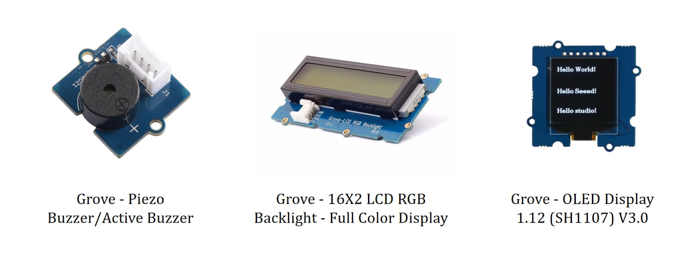
I first used the buzzer because I thought it was the simplest output and could quickly tell me whether my board, power, and pin connection were working. After that I tried a 16x2 LCD because I wanted a more visual output, finally, I changed to the Grove OLED display, which worked after several debugging rounds.
This week helped me understand that output devices deeper. The board selection, communication protocol, library, pin mapping, and even choosing the correct example code all matter.
Why I Tested Three Output Devices
At the beginning, my goal was simple: make my own board control something visible or audible. I did not want to start with the most complicated module immediately, because if it failed, it was hard for me to debug the problem came from the board, the output device, the code, or the library.
So I followed this logic:
- Buzzer first: quick proof that the board can drive an output pin.
- LCD second: try a more useful visual output for text feedback.
- OLED third: switch to a smaller I2C display after the LCD did not respond reliably.
This sequence made the troubleshooting more realistic. Each test gave me information for the next test.
Output Device 1: Grove Buzzer
What Is a Buzzer?
A buzzer is a simple output device that converts an electrical signal into sound. When the microcontroller sends a HIGH/LOW signal, the buzzer vibrates and makes a sound. Compared with a screen, it is much easier to test because it usually only needs power, ground, and one signal pin.
For this reason, I used the buzzer as my first output test. If the buzzer could make sound, then I could be more confident that my board connection and basic digital output were working.
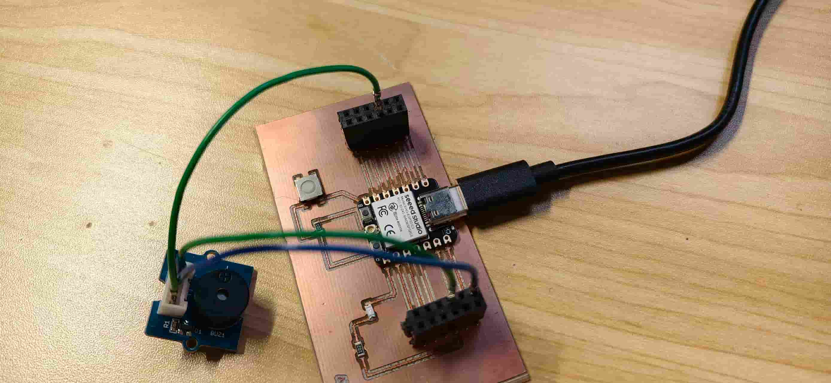
Wiring diagram to add: board signal pin to Grove buzzer SIG, plus VCC and GND.
First Test
I uploaded a very simple sketch to make the buzzer turn on. This was not an advanced sound experiment; it was mainly a sanity check.
const int buzzerPin = D2;

void setup() {

  pinMode(buzzerPin, OUTPUT);

}

void loop() {

  digitalWrite(buzzerPin, HIGH); // 响
  delay(1000);

  digitalWrite(buzzerPin, LOW);  // 停
  delay(1000);

}
Video to add: short video showing the buzzer making sound.
Result
The buzzer worked. This was a small result, but it was important because it confirmed two things:
- My board was able to control an output.
- The buzzer module itself was not damaged.
After this, I felt ready to try a display, because a screen would be much more useful for showing information in a final project.
Output Device 2: Grove 16x2 LCD
What Is an LCD?
LCD means Liquid Crystal Display. A 16x2 LCD can show 16 characters per row and 2 rows of text. It is useful when a project needs simple readable information such as status, sensor values, or menu text.
The LCD I tested was a Grove 16x2 LCD module. My expectation was that I could upload a basic "Hello World" example and see text on the screen.
Photo to add: Grove 16x2 LCD module before testing.
Screenshot to add: Arduino IDE with the LCD example sketch.
Why I Tried the LCD
After the buzzer, I wanted an output that could communicate more information than just sound. For my future final project, a text display could be useful for showing status messages such as "ready", "reading sensor", or "finished".
Also, LCDs are common in embedded projects, so I wanted to learn how to drive one.
Testing Process
I tried uploading a simple LCD test code that should display text such as Hello World. However, the screen never showed the expected text.
The symptoms were:
- Sometimes the screen was completely black.
- Sometimes it looked white or blank.
- No readable characters appeared.
- The same problem happened when I tested with a XIAO and Grove shield.
At first I suspected my own board, but testing with the XIAO and Grove shield gave the same result. That changed my thinking: the issue might not be only my board. It could be the LCD module, the library, the contrast/backlight, the I2C address, or the specific example code.
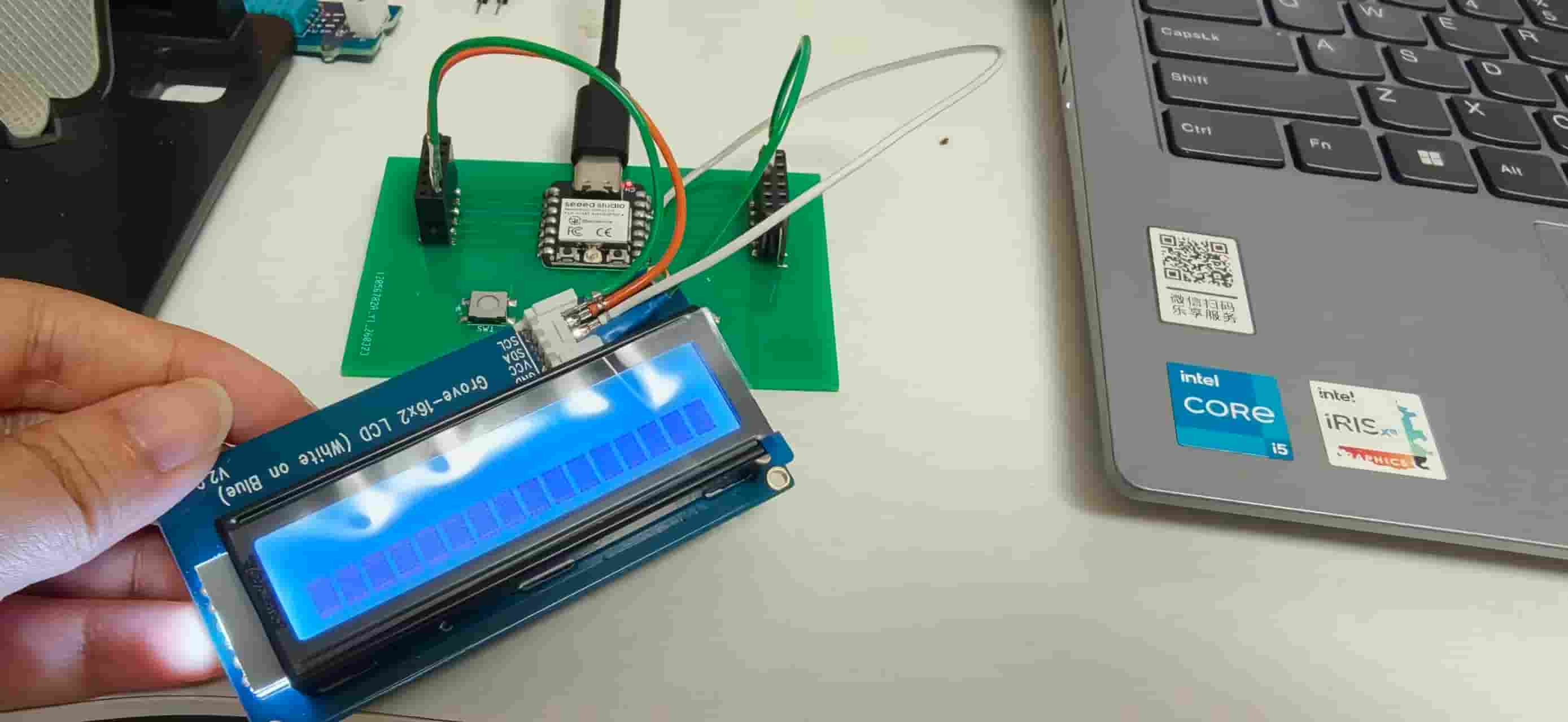
Wiring diagram to add: XIAO + Grove shield + LCD connection.
Troubleshooting
I checked the basic things first:
- The Grove cable was connected in the correct direction.
- Power and ground were connected.
- The board and port were selected correctly in Arduino IDE.
- I tried the LCD not only on my board, but also with a XIAO and Grove shield.
The LCD still did not work. At this point, my colleague suggested changing to another display because this LCD was not giving enough feedback for debugging. Since I could not interact with it and it only showed blank states, it was hard to know what was wrong.
Reflection
This was frustrating because the LCD should have been a simple display test. But it also taught me an important debugging lesson: if a module gives no useful feedback, it can waste a lot of time. Switching components is not giving up; sometimes it is a better way to isolate the problem.
The LCD test failed, but it helped me make a better decision for the next experiment.
Output Device 3: Grove OLED 1.12 Inch Display
What Is an OLED?
OLED means Organic Light-Emitting Diode. Unlike an LCD, each pixel in an OLED can emit its own light. This gives strong contrast and makes the display readable even without a backlight.
The Grove OLED 1.12 inch display I used is a small screen, but it can show text and simple graphics. It is more flexible than the buzzer and more compact than the 16x2 LCD. This made it a good choice after the LCD test failed.
Photo to add: Grove OLED module close-up.
I2C Communication
The OLED communicates with the microcontroller using I2C. I2C is a two-wire communication protocol:
- SDA carries the data.
- SCL carries the clock signal.
Many devices can share the same I2C bus, and each device has an address. For small display modules, common I2C addresses are often 0x3C or 0x3D.
For this week, I learned that using I2C means I need to pay attention to:
- the correct SDA and SCL pins,
- the correct display driver or library,
- the correct board selected in Arduino IDE,
- and the correct example code for the display controller.
Wiring diagram to add: OLED VCC/GND/SDA/SCL connected to the XIAO or my custom board.
Screenshot to add: Serial Monitor showing the I2C scanner result.
First OLED Attempt: JLCPCB Board and "Snow" on the Screen
My first OLED test was with the JLCPCB version of my board. The OLED did light up, but it showed noisy "snow" instead of the clean text or graphics I expected.
At first, this looked like a hardware problem. But later I realized the problem was more about my setup: I had selected the wrong board or used the wrong code for the display. Because OLED libraries are quite specific, using an example for the wrong display controller can create strange results.
Screenshot to add: Arduino IDE board selection that caused the mistake, if available.
This was an important failed result. It showed that "the screen lights up" does not always mean the code and driver are correct.
Second OLED Attempt: XIAO + Grove Shield
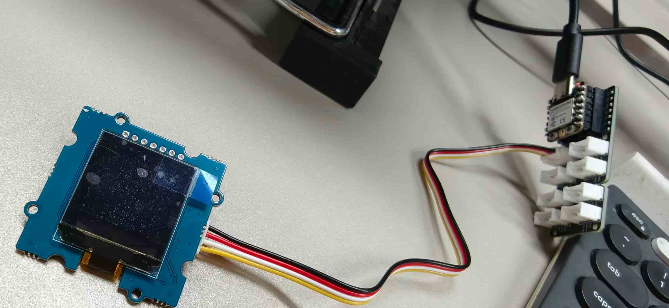
To reduce the number of possible problems, I moved the OLED to a simpler setup: XIAO + Grove shield.
This was a useful debugging step because the Grove shield gave me a more standard and reliable connection. If the OLED worked there, then I could prove that:
- the OLED module was good,
- the library could drive it,
- and the problem was not the display itself.
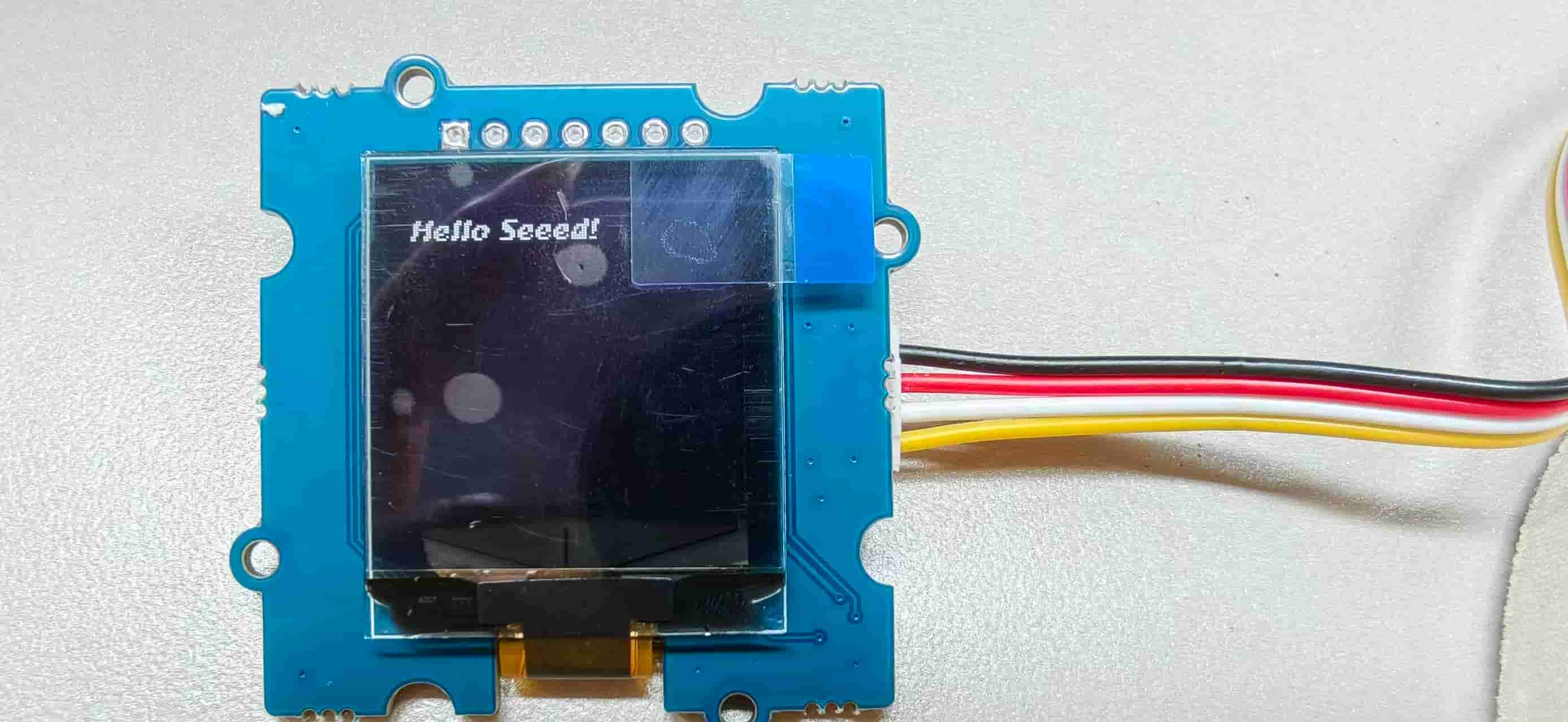
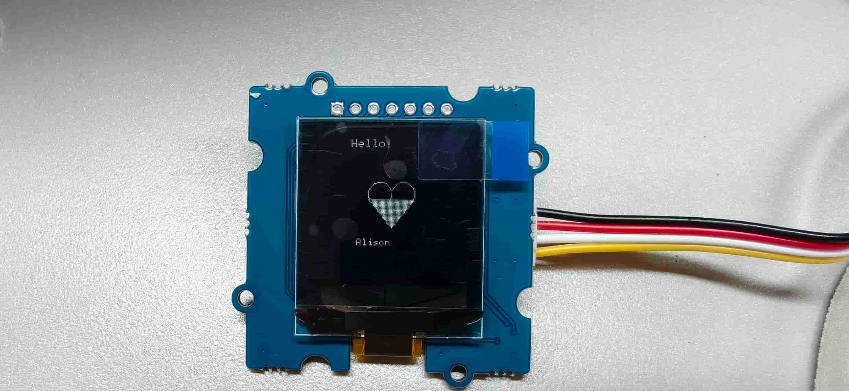
This time the OLED worked. I first uploaded a simple test and confirmed that the display could turn on correctly. Then I changed the code to draw text and simple graphics, including Hello! and Alison.
The final sketch used the U8g2 library:
#include <Arduino.h>
#include <U8g2lib.h>
#include <SPI.h>
#include <Wire.h>

U8G2_SH1107_SEEED_128X128_1_SW_I2C u8g2(
  U8G2_R0,
  /* clock=*/ SCL,
  /* data=*/ SDA,
  /* reset=*/ U8X8_PIN_NONE
);
The drawing part created text and a simple heart-like graphic:
u8g2.setFont(u8g2_font_6x10_tf);
u8g2.drawStr(30, 15, "Hello!");
u8g2.drawCircle(55, 55, 10, U8G2_DRAW_ALL);
u8g2.drawCircle(75, 55, 10, U8G2_DRAW_ALL);
u8g2.drawTriangle(45, 60, 85, 60, 65, 85);
u8g2.setFont(u8g2_font_5x7_tf);
u8g2.drawStr(35, 100, "Alison");
Video to add: short clip of the OLED powered by the XIAO + Grove shield.
Downloadable sketches:
Third OLED Attempt: My Own Board
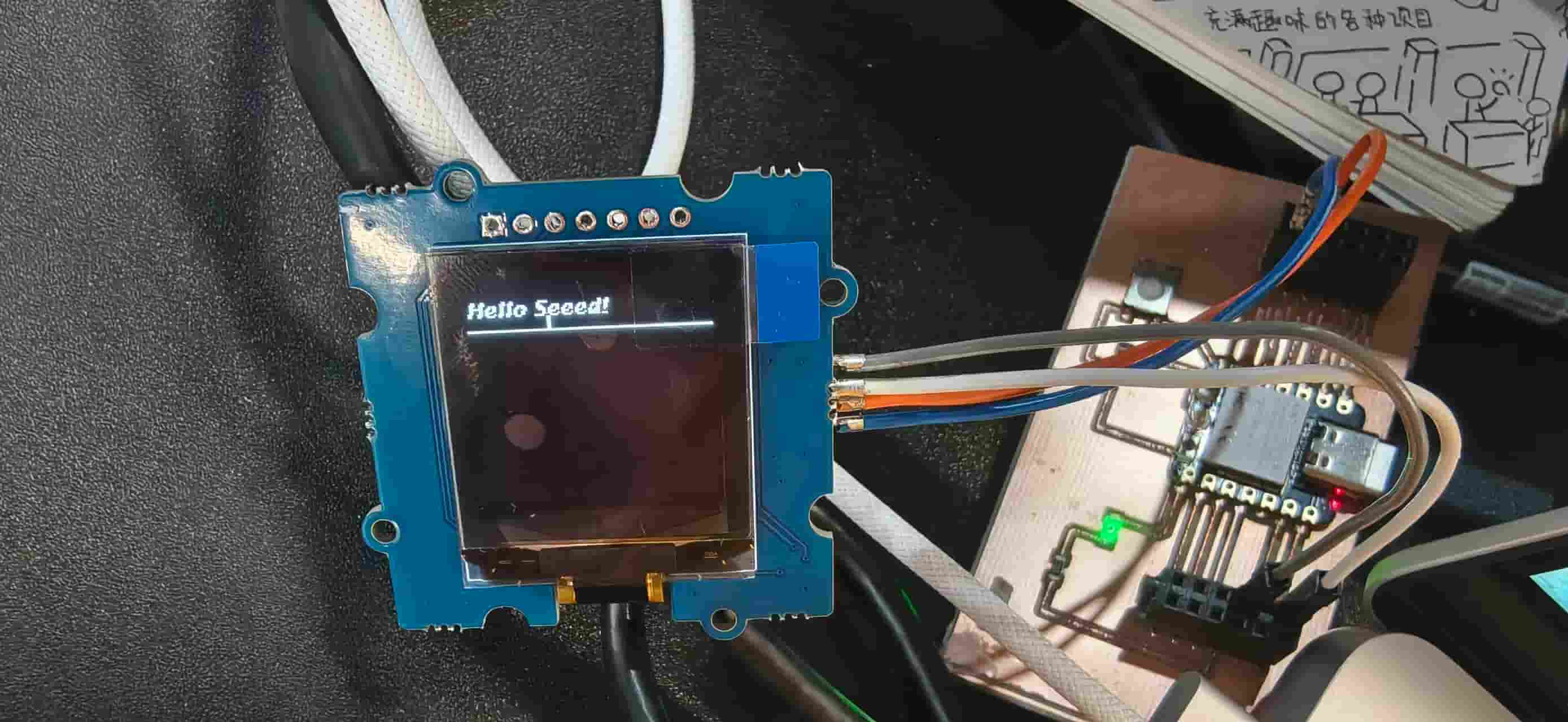
After the OLED worked on the XIAO + Grove shield, I moved back to my own board. This was the real assignment target: not only test an output device on a standard development board, but make it work with the board I designed.
This time the OLED successfully lit up and displayed the content.
Video to add: final successful OLED test on my own board.
This was the most satisfying part of the week because the debugging path finally made sense:
- The buzzer proved that a basic output worked.
- The LCD failed even on a standard setup, so I changed direction.
- The OLED first showed problems, but then worked after I corrected the board/code setup.
- The final OLED test worked on my own board.
Troubleshooting Summary
| Problem | What I Observed | What I Tried | Result / Learning |
|---|---|---|---|
| Need to confirm board output | I did not know if my board could drive an output | Tested Grove buzzer with simple code | Buzzer worked, so the board and output pin were basically OK |
| LCD did not display text | Black or white screen, no characters | Tried code, checked wiring, tested with XIAO + Grove shield | Still failed, so I switched to another display |
| OLED showed snow/noise | Display lit up but content was not correct | Rechecked board selection and code | Wrong setup/code can cause display noise |
| Need to isolate OLED problem | Unsure if OLED or board was the issue | Tested OLED on XIAO + Grove shield | OLED worked, so the module and library were OK |
| Need final assignment result | Output had to work on my own board | Moved OLED back to my board | OLED successfully displayed content |
What I Learned
This week helped me understand output devices from a practical debugging perspective.
The buzzer was useful because it gave fast feedback. The LCD was useful even though it failed, because it taught me when to stop spending time on a module that is not providing debugging information. The OLED was the best final choice because it gave visual output, used I2C communication, and could show both text and simple graphics.
I also learned that the software side of output devices is very dependent on the exact hardware. For displays, choosing the correct library and display constructor is just as important as wiring SDA, SCL, VCC, and GND correctly.
Connection to My Final Project
For my final project, I will probably need some kind of feedback from the device to the user. This week gave me three possible types of feedback:
- Sound feedback: a buzzer can quickly alert the user when something happens.
- Text feedback: a display can show status, sensor values, or instructions.
- Graphic feedback: an OLED can show simple icons, progress, or a more personal interface.
The OLED feels like the best option for my future project because it is small, expressive, and uses only a few pins through I2C. I can imagine using it to show system status, sensor readings, or a simple message for the user.
Final Result
My final successful output device for Week 10 was the Grove OLED 1.12 inch display. I successfully tested it first with the XIAO + Grove shield, then moved it back to my own board and displayed a custom Hello! and Alison graphic.
This week was not perfect, but it was realistic. I had a successful buzzer test, a failed LCD test, an OLED test with noise, and finally a working OLED output. The debugging process helped me become more confident in checking output devices step by step instead of assuming the problem is only in the code.