Week 02: Computer-Aided Design
Introduction
I have always enjoyed drawing by hand, and I often sketch ideas first on paper.
However, hand drawings can fade over time, get damaged, or be difficult to edit precisely. Thanks to how technology has developed, tools like Canva and PowerPoint are great for starters like me, even designing event posters is not too difficult. Even so, I was mostly using them in a practical way, without really understanding how digital images and models are constructed.
This week, Sophia and Kenny introduced us to the fundamentals of 2D and 3D design, and that helped me start building that foundation. I began to understand that in digital fabrication, design is not only about making something look nice, it is also about understanding file types, geometry, paths, and how machines read design data.
Bitmap & Vector Graphics
Bitmap (Raster) Images
A bitmap image is a grid of pixels. Each pixel stores a color value. A 1200 × 800 image contains 960,000 individual color values stored in order.
When we zoom in, the pixels stretch, the image becomes blurry because no new information exists. This is a fundamental limit of the format.
Common formats: JPG, PNG, GIF, BMP, TIFF
| Format | Best for | Notes |
|---|---|---|
| JPG | Photos, web images | Lossy compression, smaller file size |
| PNG | Screenshots, logos, transparency | Lossless, larger file size |
Bitmaps are ideal for photographs and scanned images. They are not suitable for scaling up or for machine tool paths.
Vector Images
A vector image stores mathematical descriptions of geometry, points, lines, curves, and polygons, rather than pixels. A circle is stored as a center position and radius, not as thousands of colored squares. When scaled, the computer recalculates the formula, so the image stays sharp at any size.
Common formats: SVG, EPS, PDF, AI
Vector files are essential for digital fabrication because CNC machines and laser cutters follow paths, not pixels. If you send a bitmap to a laser cutter, it has no path to cut along.
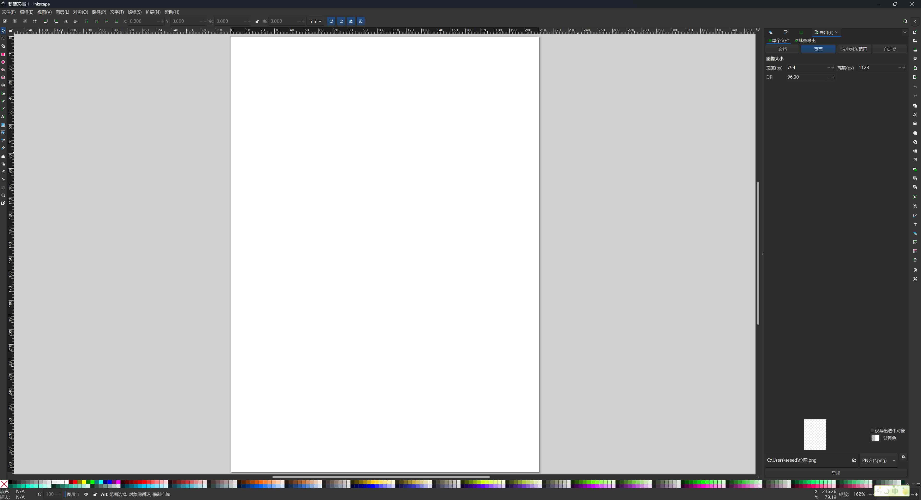
Tools: GIMP and Inkscape
I explored two free, open-source tools that serve different roles in a fabrication workflow.
GIMP — Raster Image Editor
GIMP (GNU Image Manipulation Program) works with pixels, similar to Photoshop. Its native format is XCF (which preserves layers), and it exports to PNG, JPG, and other raster formats.
Typical fabrication uses: cleaning up scanned artwork, removing backgrounds before importing to Inkscape, adjusting contrast on a photo before tracing.
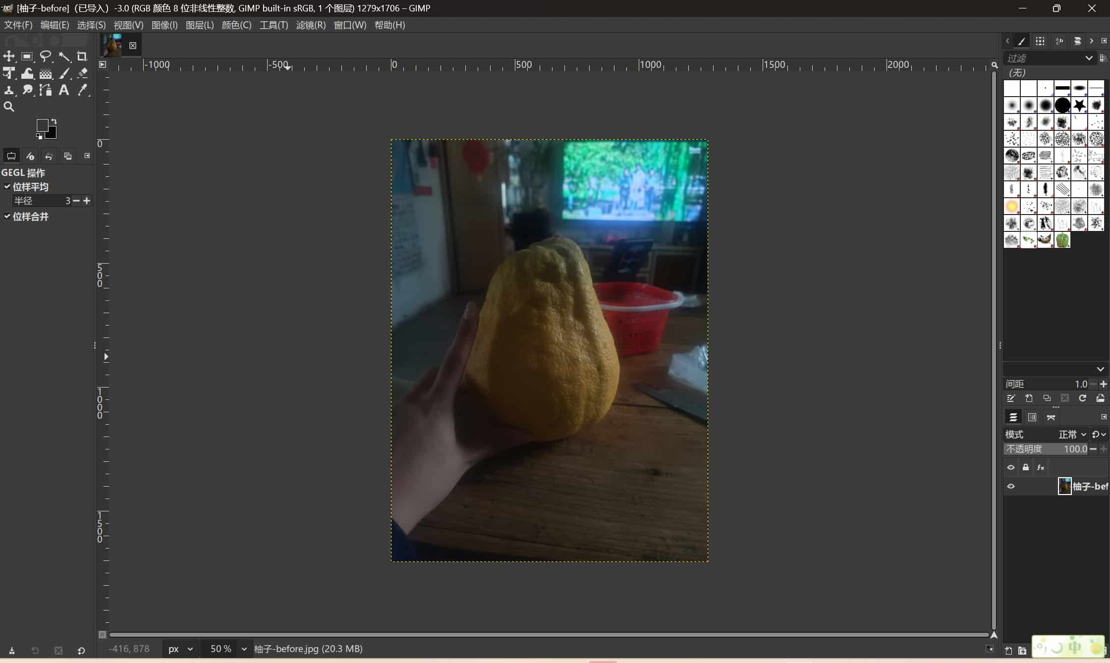
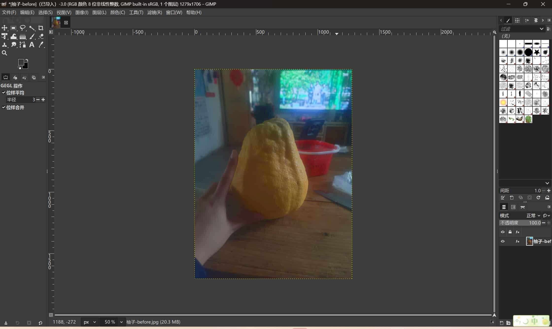
My practice: I edited a grapefruit photo that was slightly dark. In GIMP I went to Colors → Hue-Saturation, increased Saturation by 10, and exported the result as PNG.
Before (original):
After (saturation +10):
This was a simple exercise. The more useful GIMP skill for fabrication is background removal before tracing in Inkscape — a cleaner input image produces a cleaner vector trace.
Inkscape — Vector Graphics Editor
Inkscape works with SVG files and allows precise editing of paths, nodes, strokes, fills, and dimensions. It is the primary 2D tool for laser cutting and vinyl cutting at Fab Academy because it can output files with exact millimeter dimensions and clean closed paths.
Typical Workflow: Bitmap to Vector
A standard combined workflow:
- Clean or adjust a bitmap in GIMP (remove background, improve contrast).
- Export as PNG.
- Import PNG into Inkscape.
- Use Path → Trace Bitmap to convert it to vector paths.
- Clean up nodes and close any open paths.
- Set exact dimensions.
- Export as SVG or DXF for the fabrication tool.
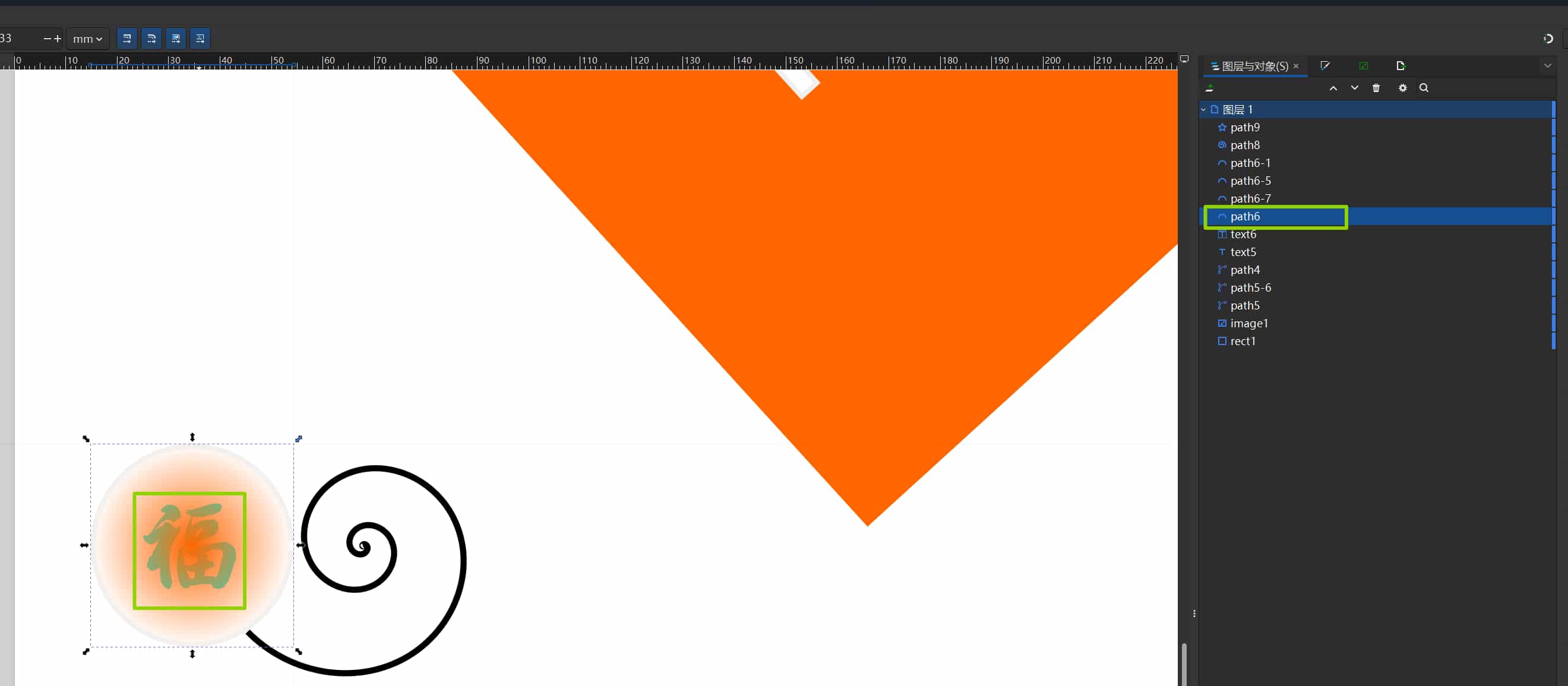
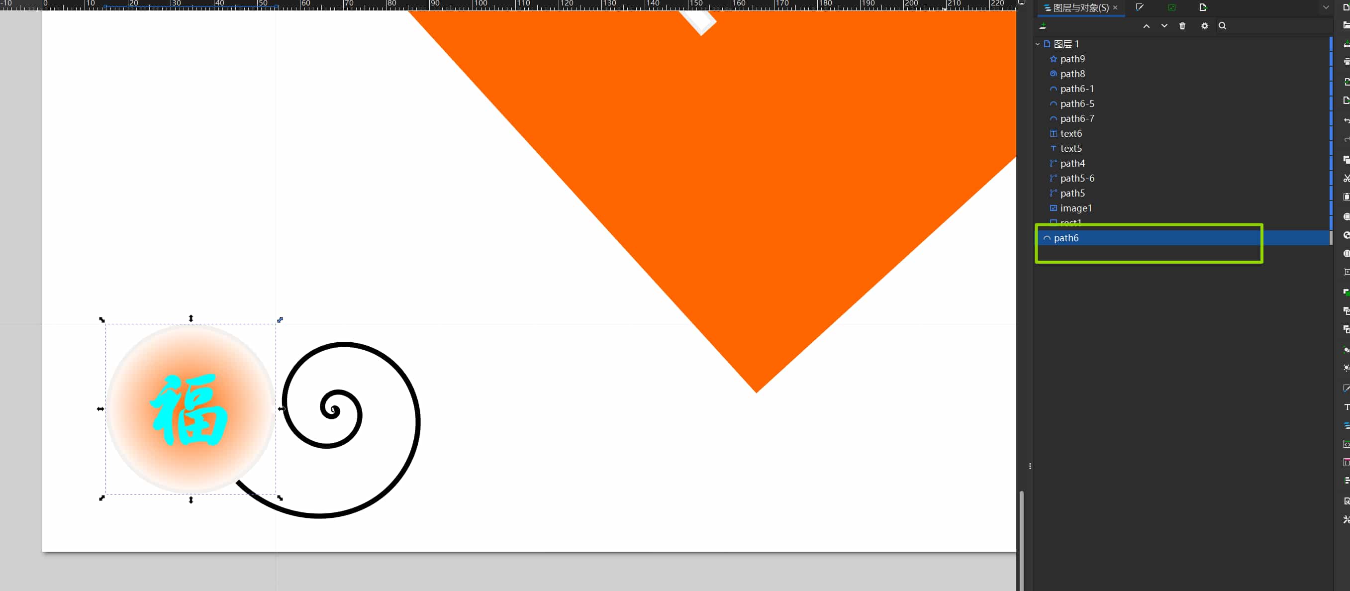
My 2D Project: Fu Panel with Screen Cutout
This week I designed a decorative "Fu" (福) panel in Inkscape. The panel has a cutout for a Seeed e-paper display and is intended for my final project.
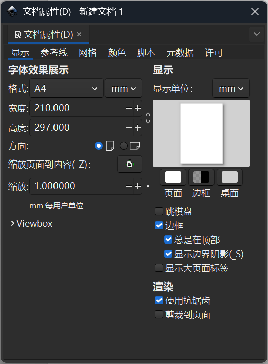
Setting Up the Document
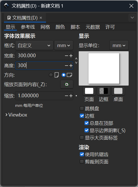
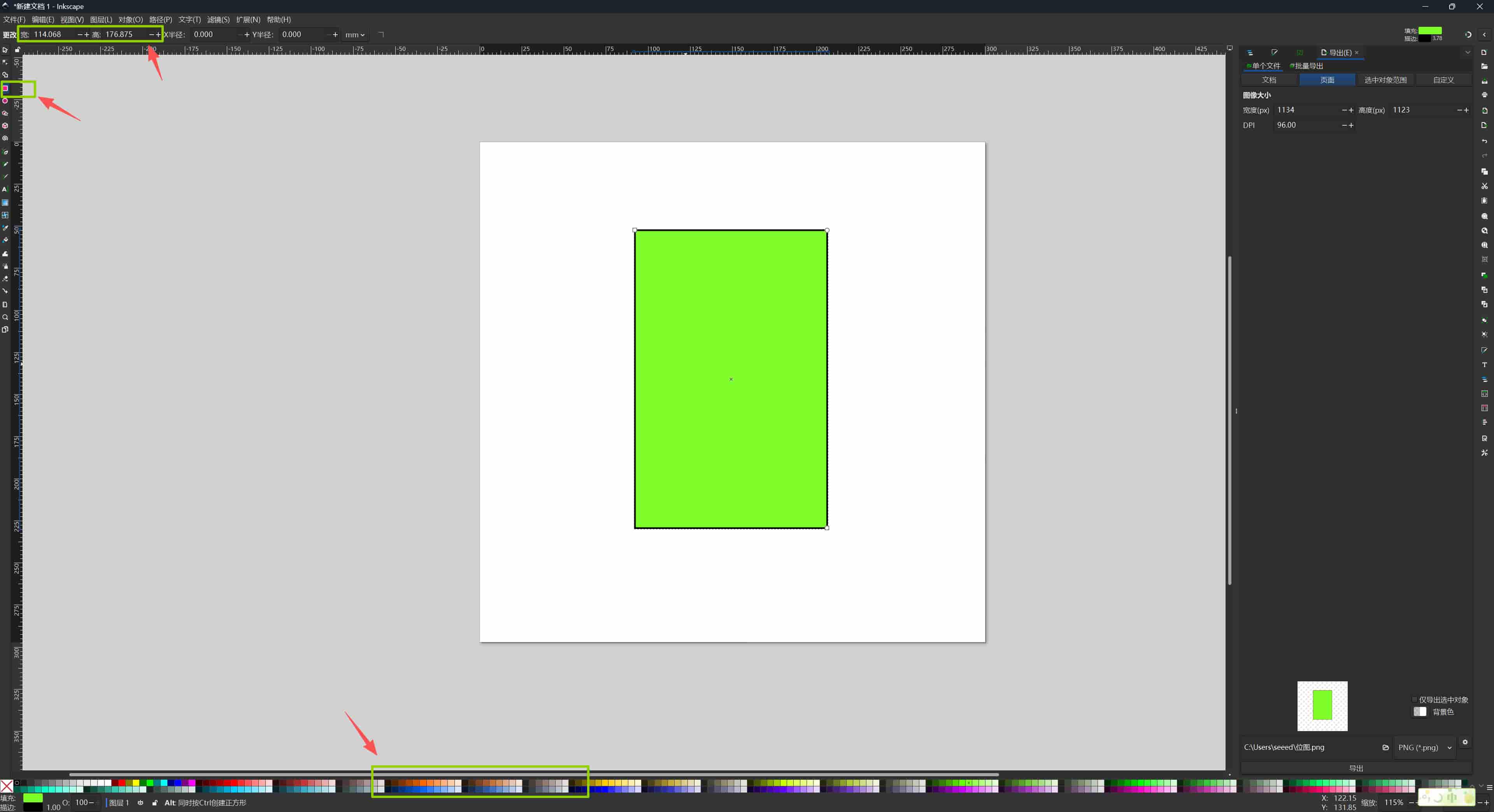
When I opened Inkscape, the layout has three main zones: page settings at the top, drawing tools on the left (rectangles, polygons, circles, Bézier pen), and object properties on the right showing size and position numerically.
I set the document to 300 × 300 mm in File → Document Properties to match the intended frame size.
Drawing the Screen Cutout
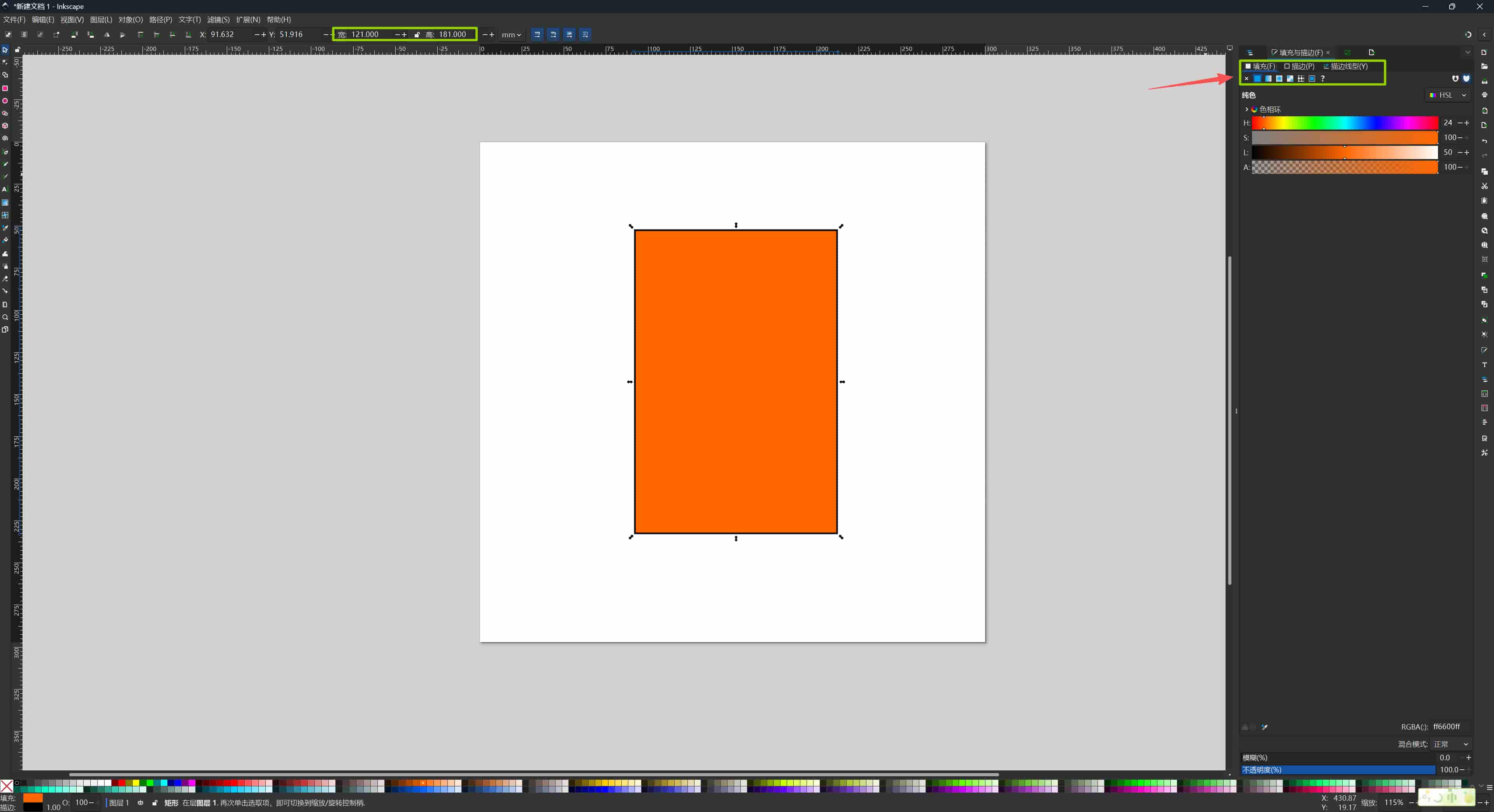
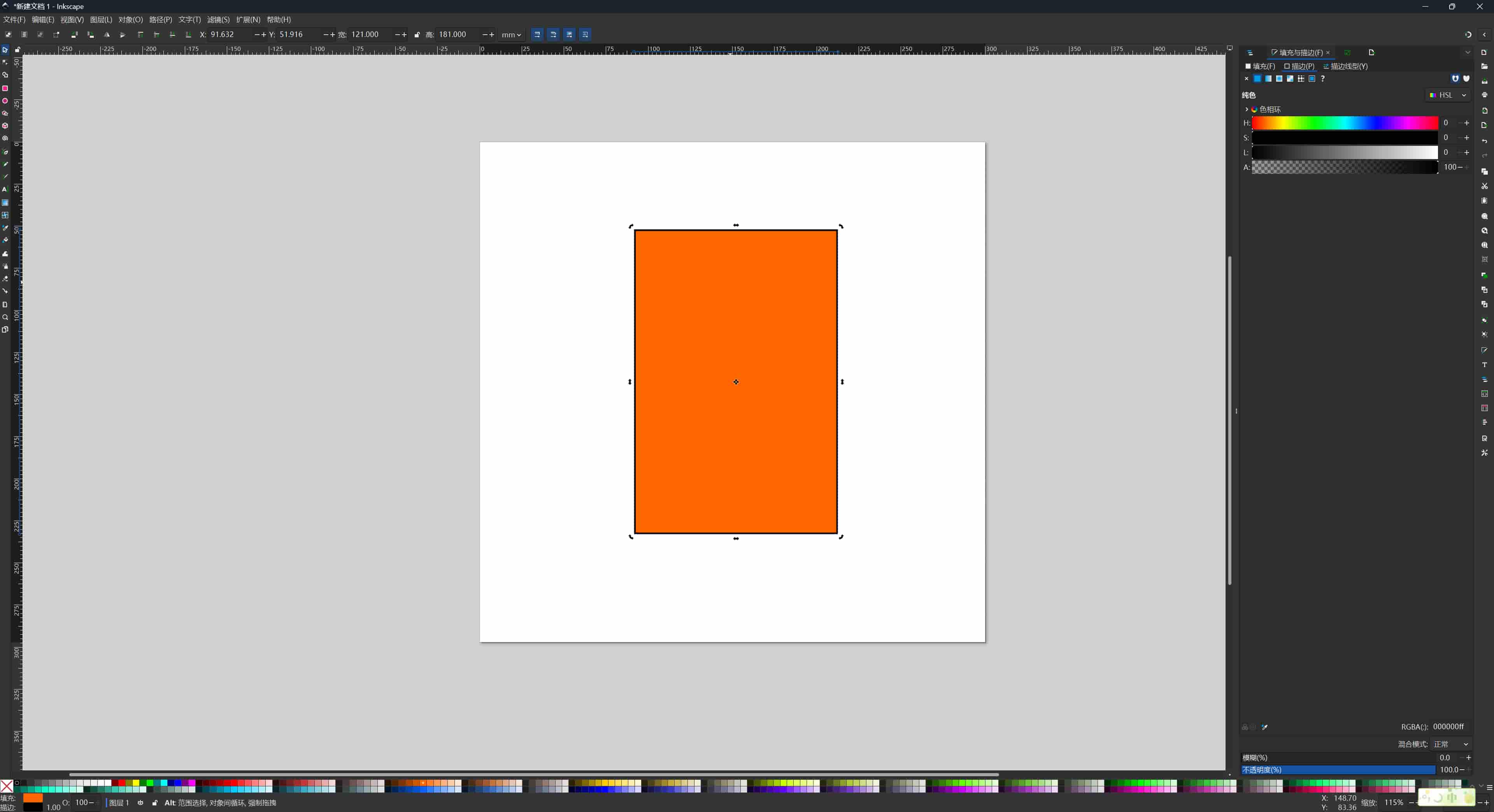
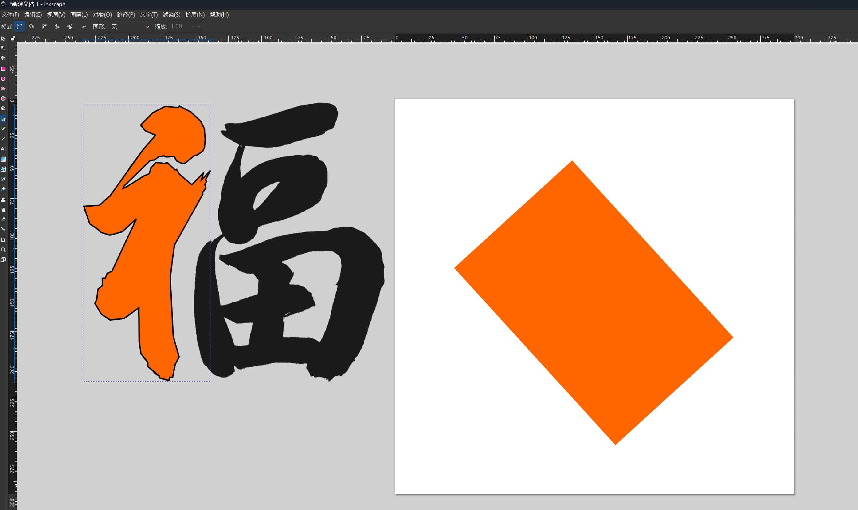
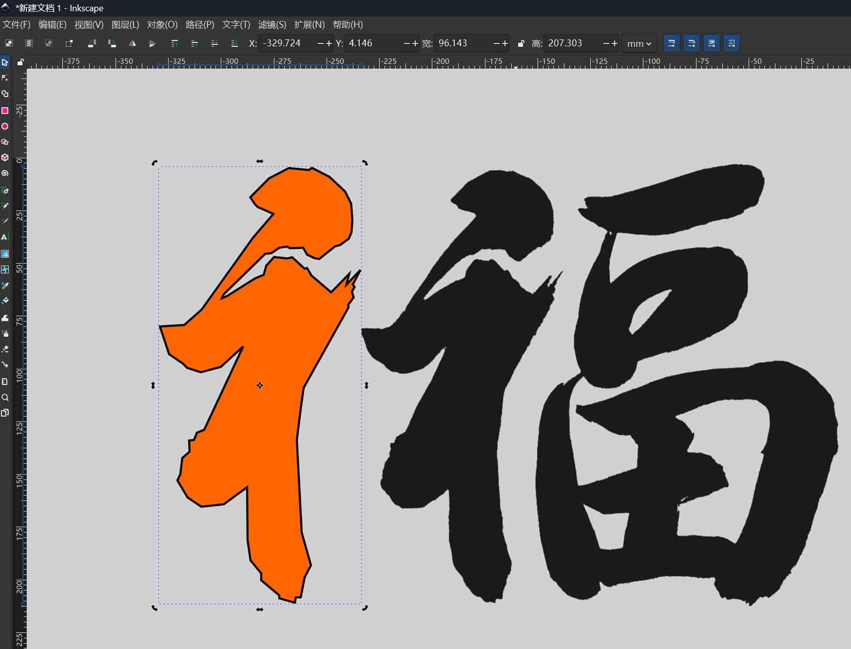
I drew a rectangle in the center using the Rectangle tool and set its size to exactly 120 × 180 mm in the W/H fields on the toolbar. This matches the Seeed e-ink display I plan to use, so the cutout represents exactly where the screen will sit in the frame.
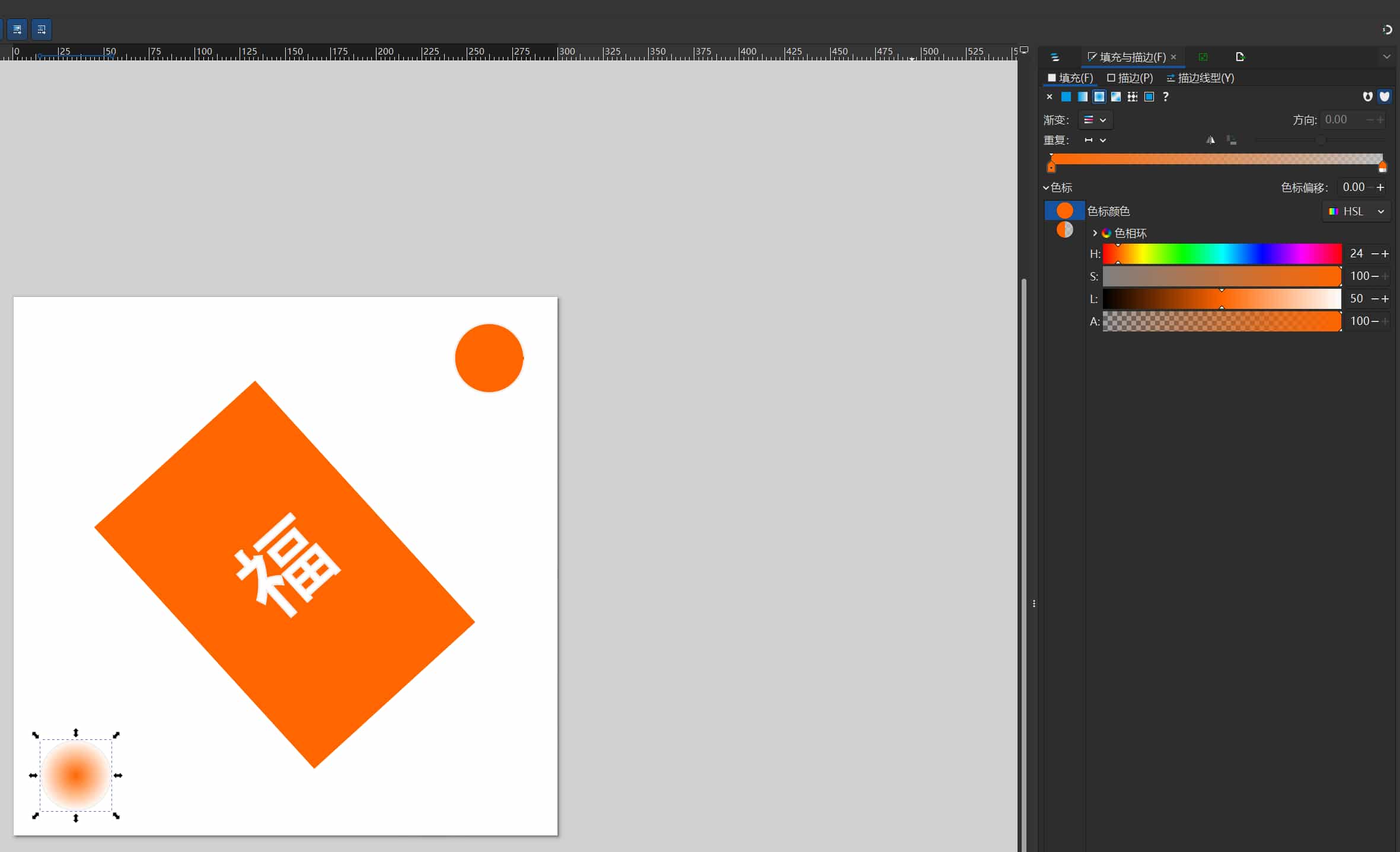
I changed the fill color from default green to light orange to make it visually distinct from the frame outline.
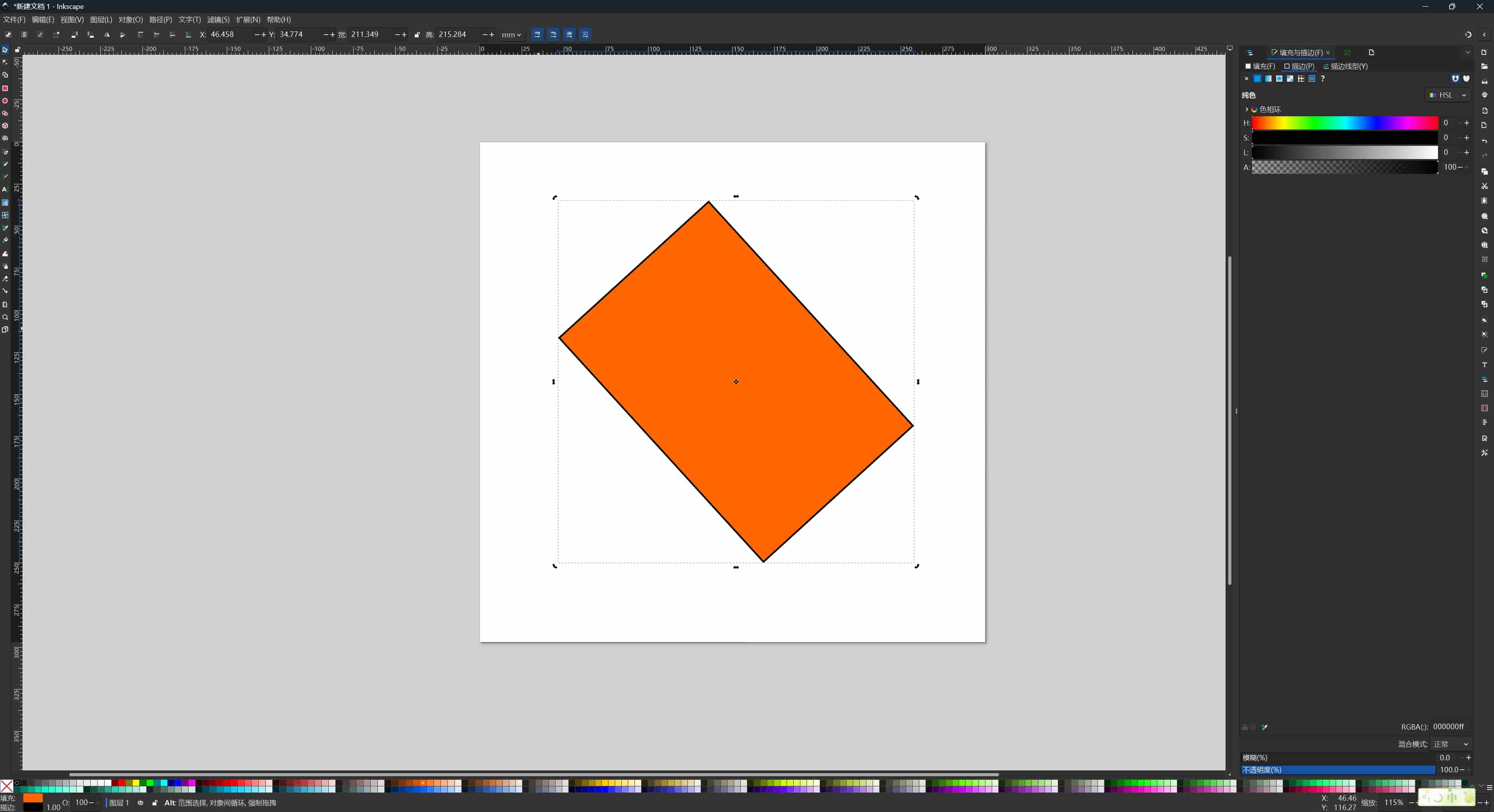
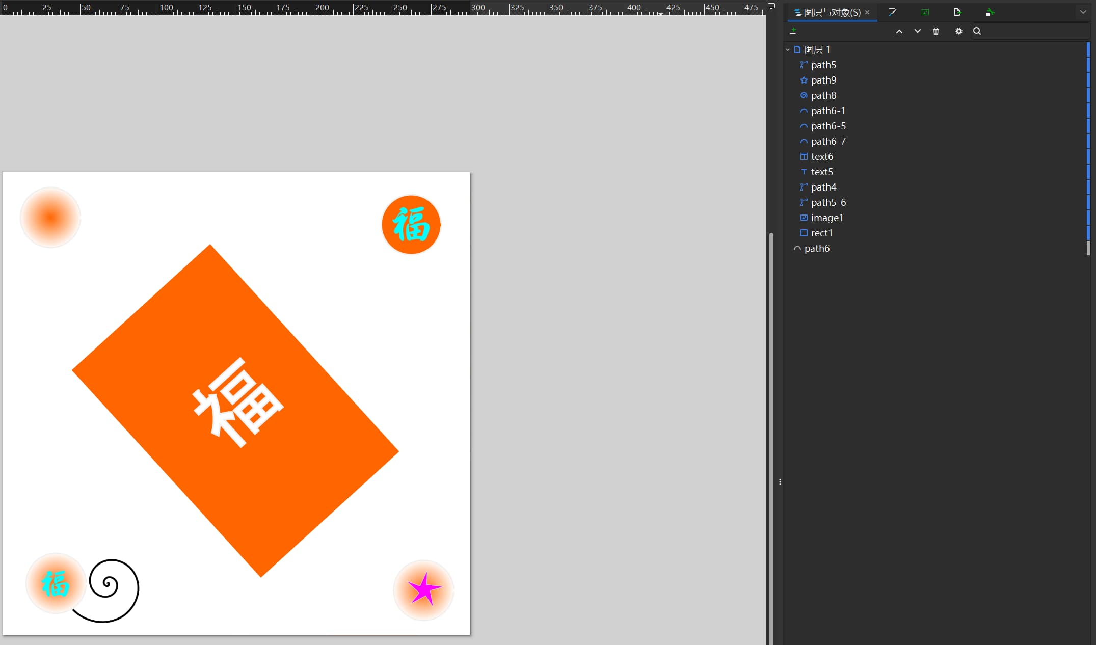
Rotating the Frame
My outer frame is meant to read as a tilted prism-like panel, so I rotated the outer rectangle. Clicking the shape once shows resize handles; clicking again switches to rotation handles (curved arrows at the corners). I dragged to rotate it to the angle I wanted.
After rotation, the bounding box displayed by Inkscape is larger than the shape itself, this is normal behavior. The bounding box shows the axis-aligned extents of the tilted rectangle, not the shape's own dimensions.
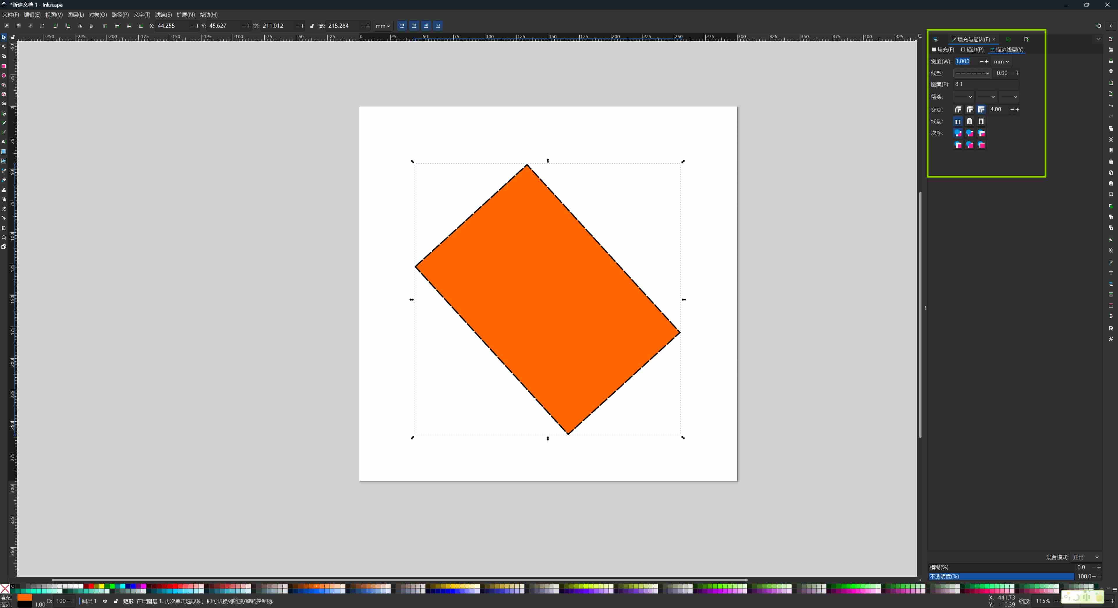
I then opened the Fill and Stroke dialog (Object → Fill and Stroke) and edited the stroke: I set the width, color, and applied a radial gradient to the stroke so the line fades from the center outward. This gave the outline a subtle light-spreading effect.
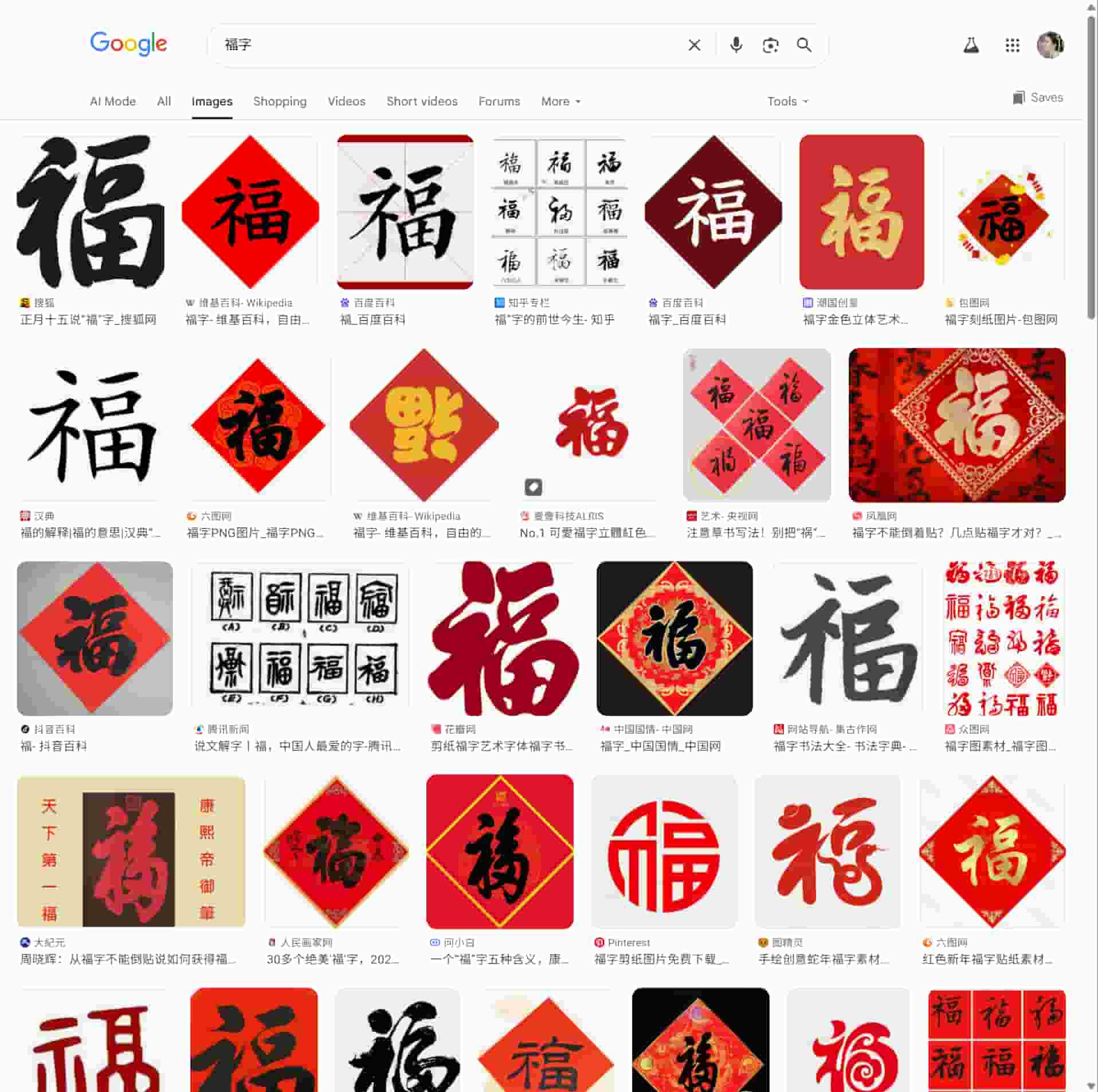
Importing Reference Artwork
I searched Google and Pinterest for 福 character designs I liked. I copied a reference image into Inkscape and placed it on the artboard. To scale it without distorting the proportions, I held Ctrl while dragging a corner handle.
Tracing: Two Methods
I tried two approaches to convert the bitmap reference into vector paths.
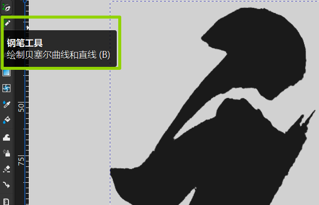
Method 1 — Manual pen trace:
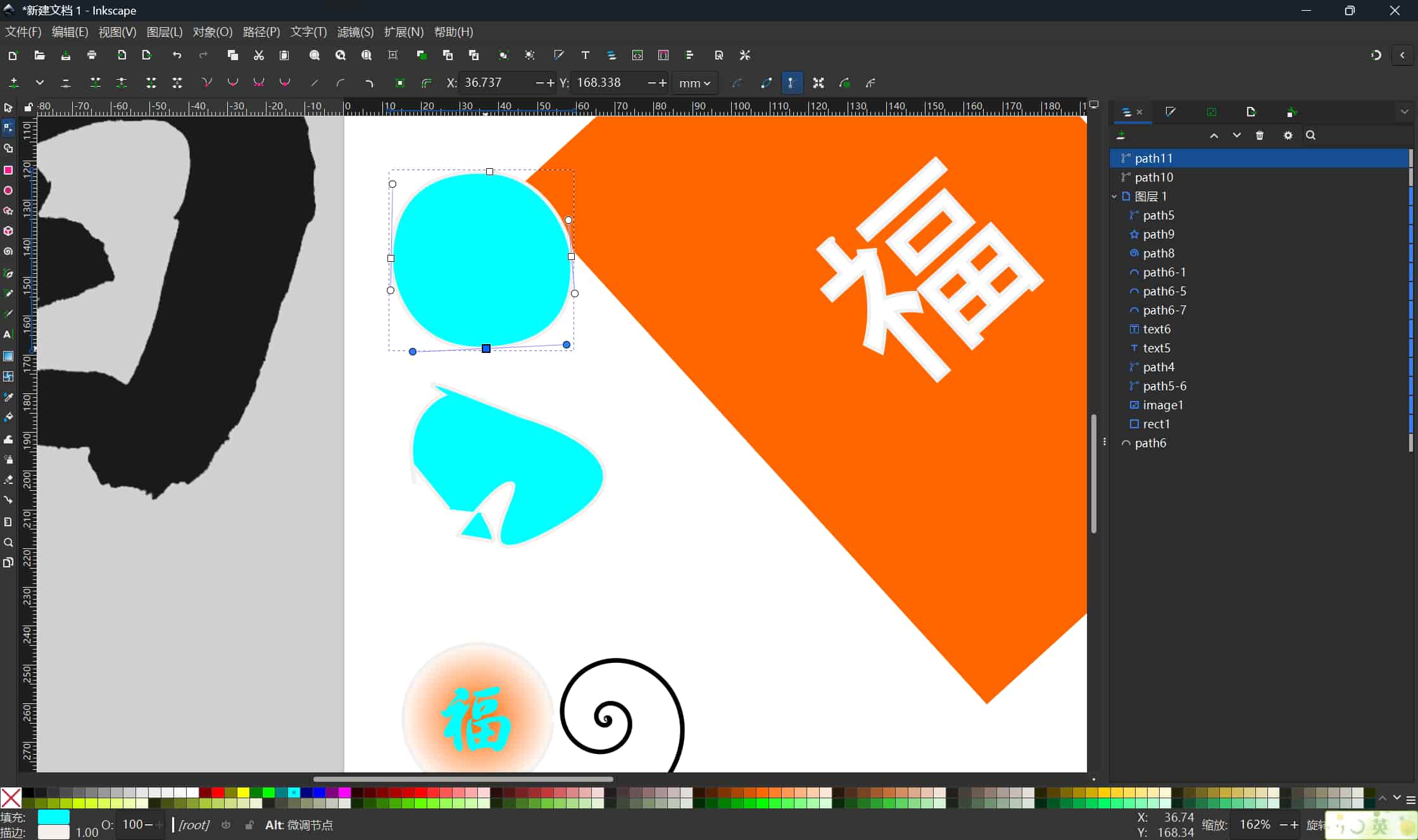
I enlarged the reference image and traced it with the Bézier pen tool, clicking to place anchor points and dragging to create curved handles along each stroke. This is slow but gives full control over every node.
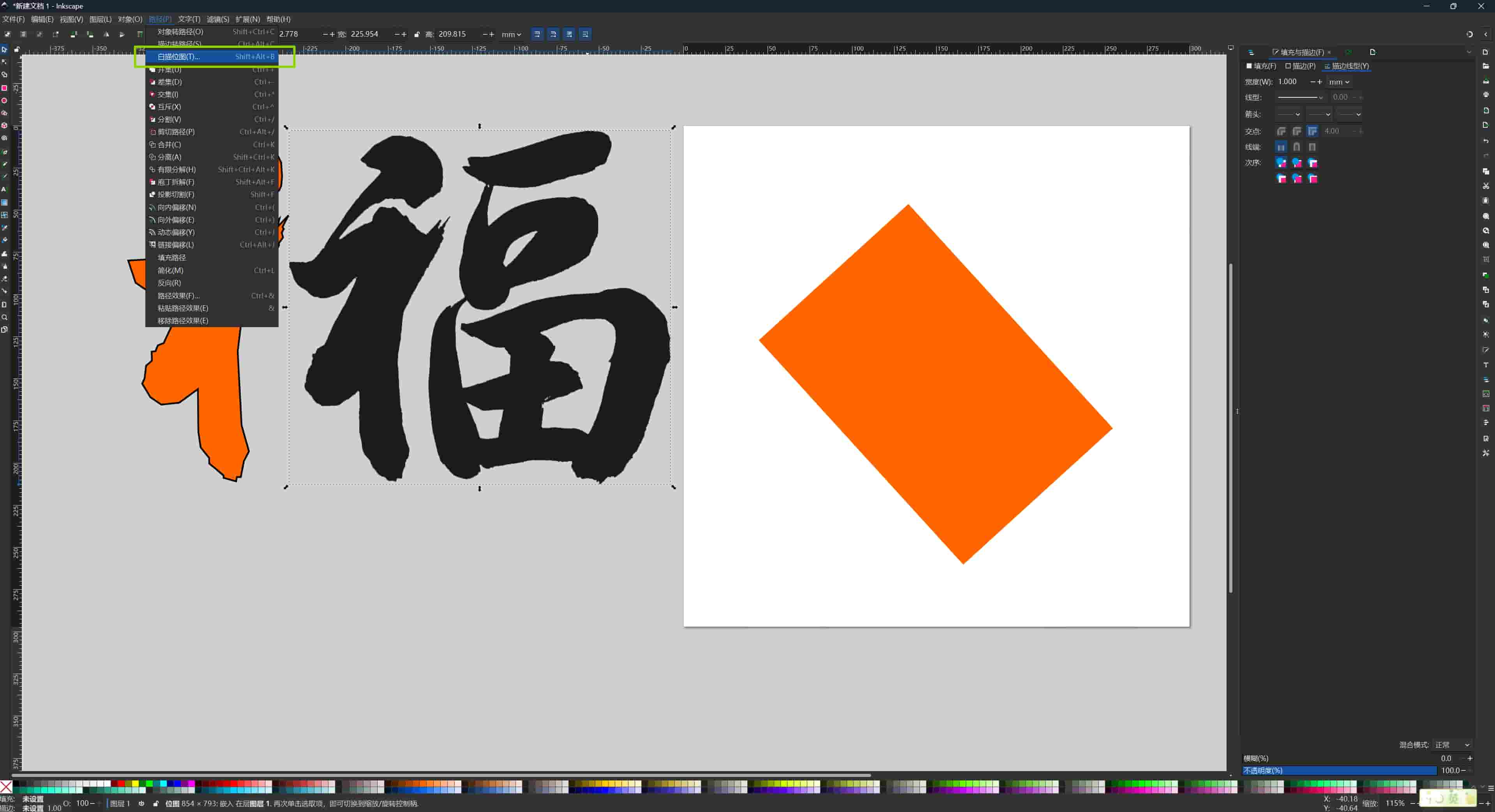
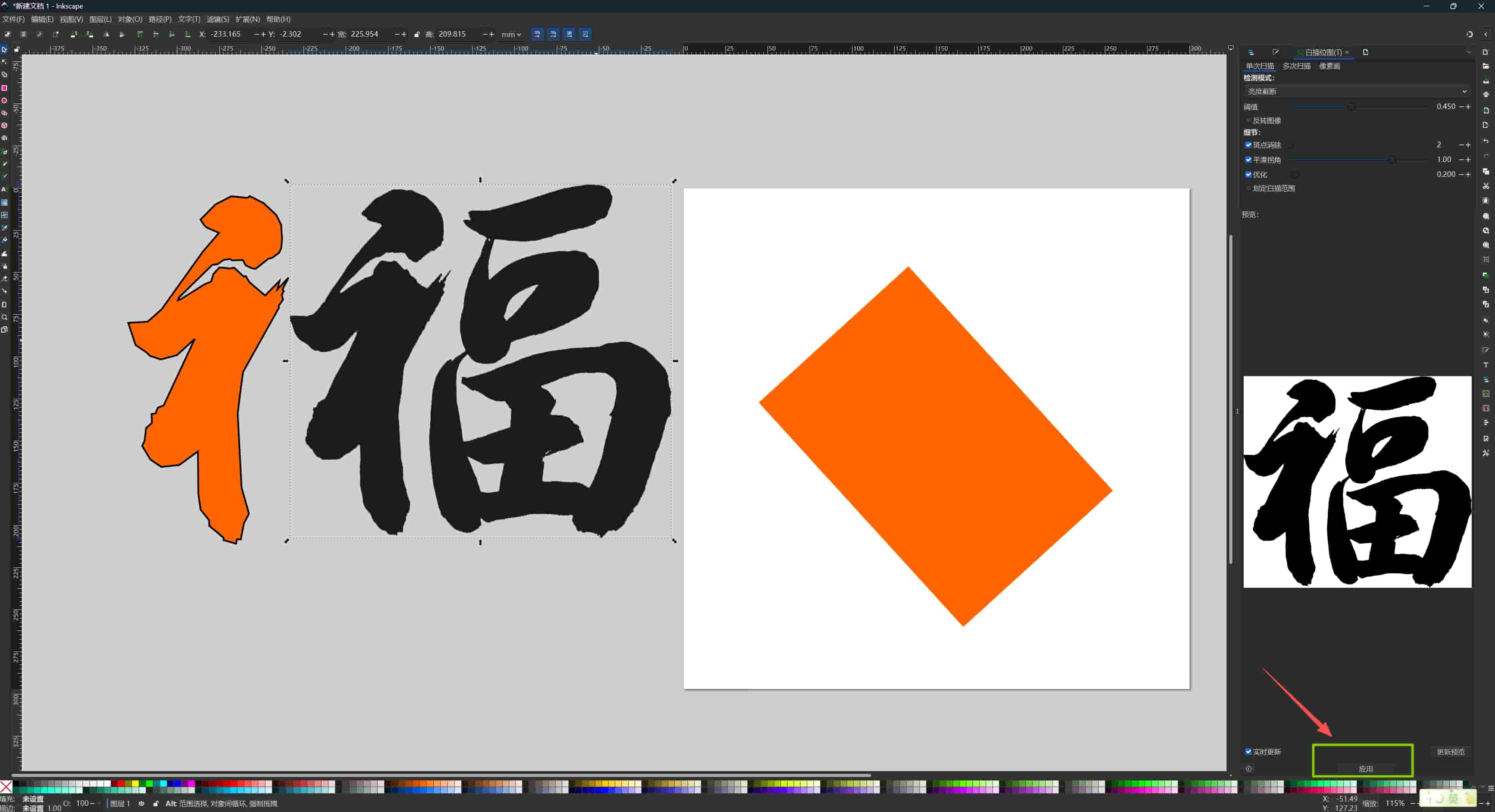
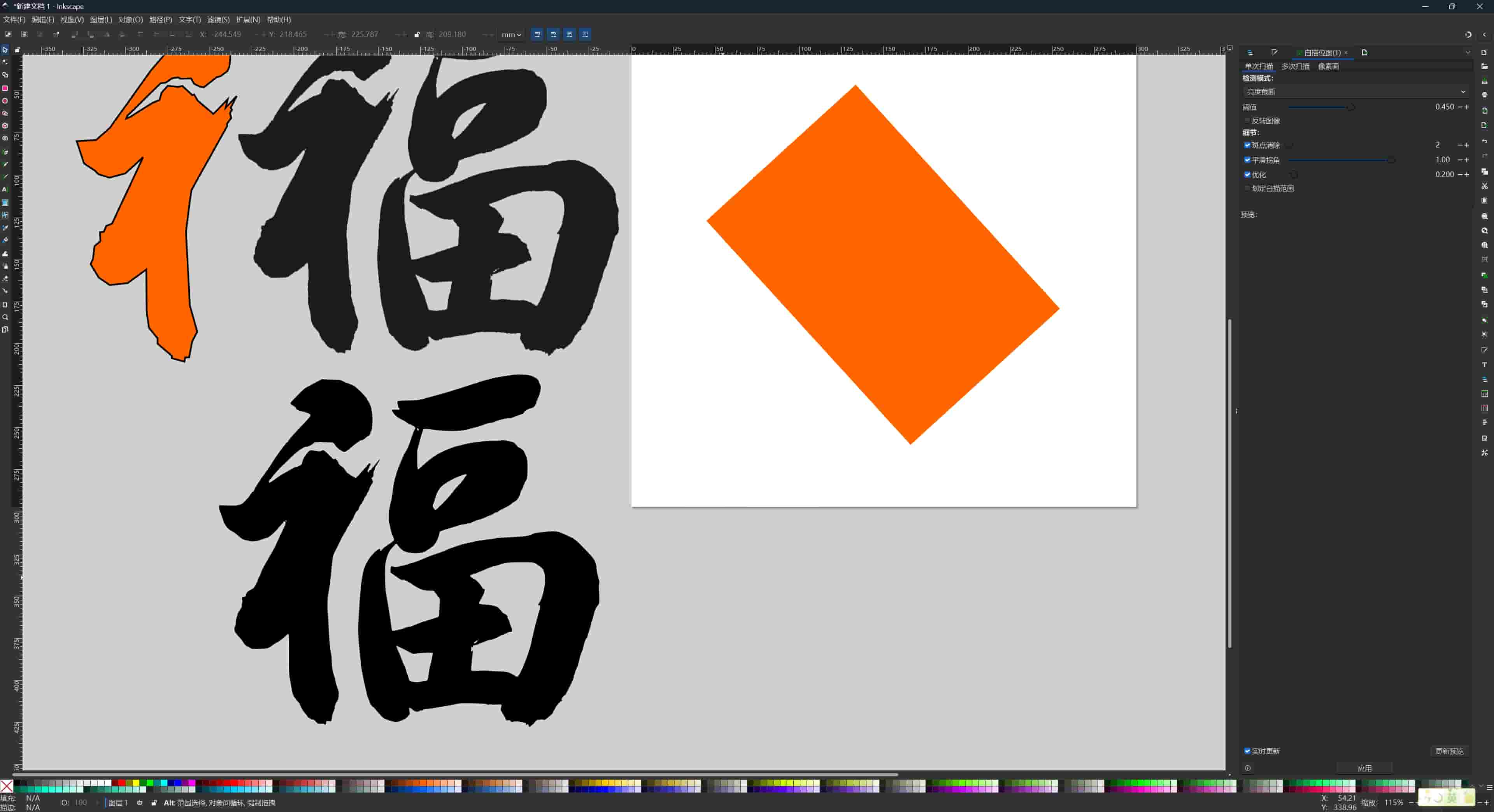
Method 2 — Automatic Trace Bitmap:
I used Path → Trace Bitmap with the following settings:
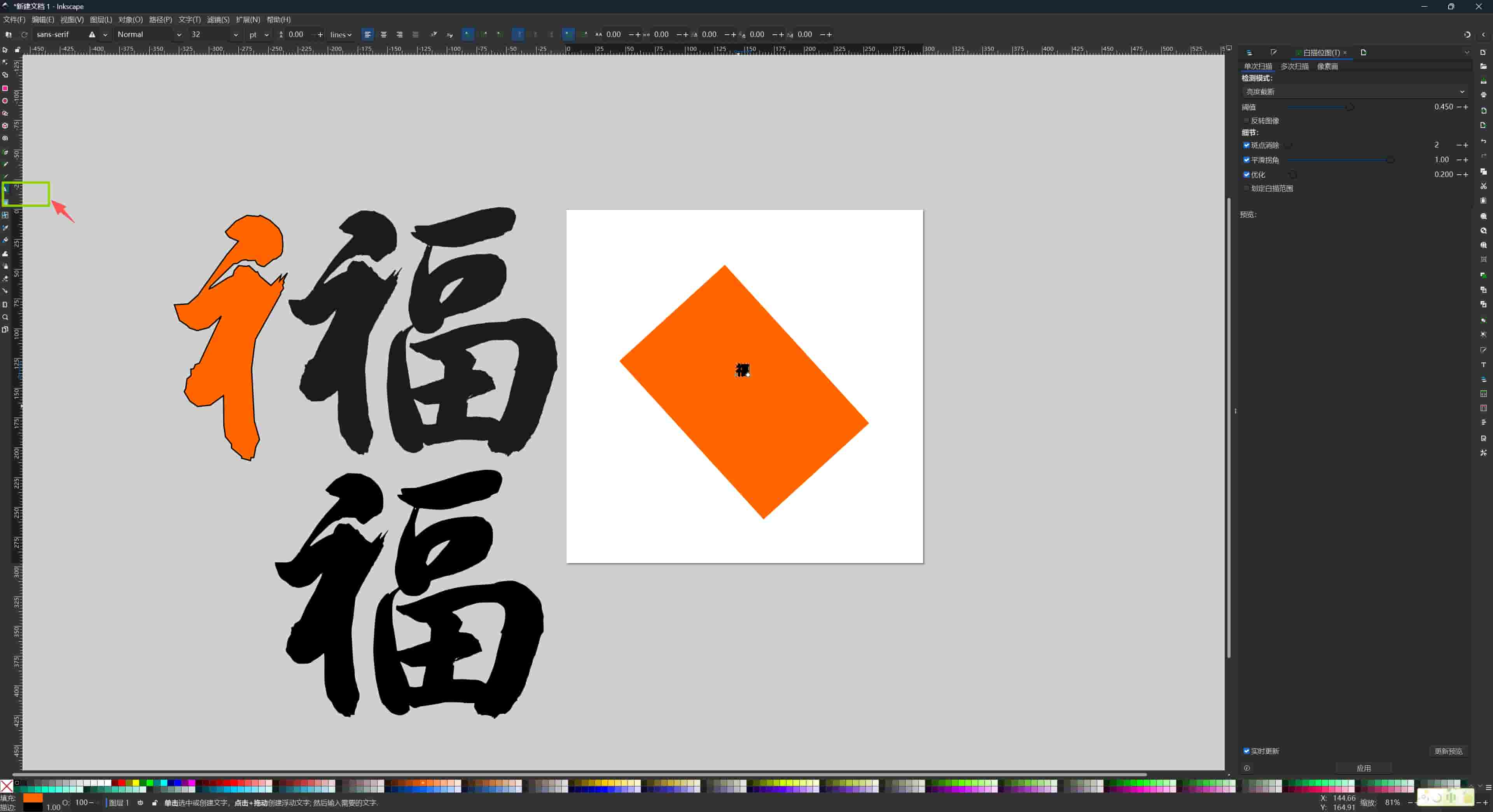
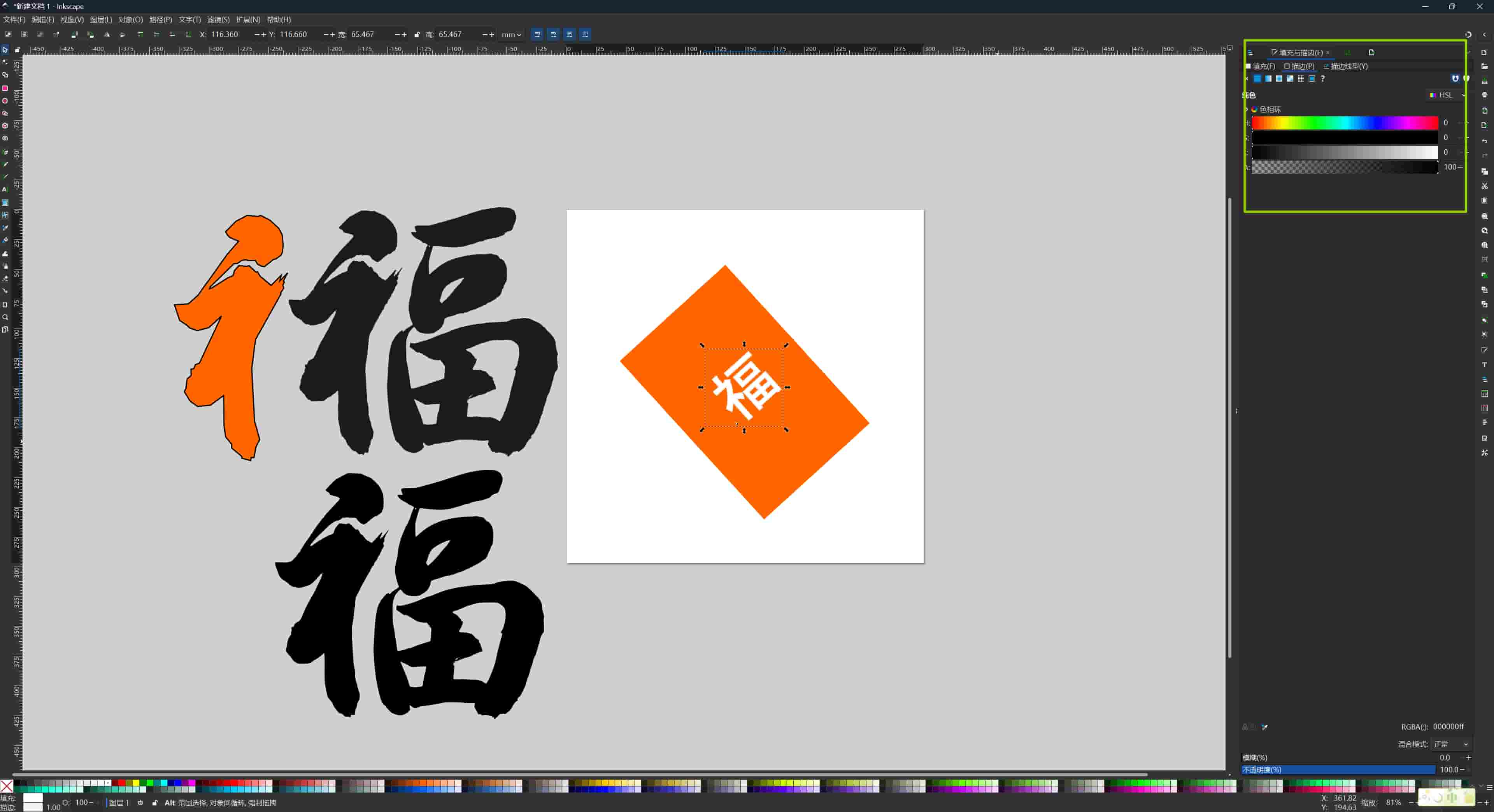
Inkscape generated a vector path from the pixel data. The result had many nodes — some edges were noisy. I then used the Node editor (N) to select and delete redundant nodes, and adjusted handles on curves to smooth the strokes.
The character placed inside the frame gave a preview of the "screen in panel" layout.
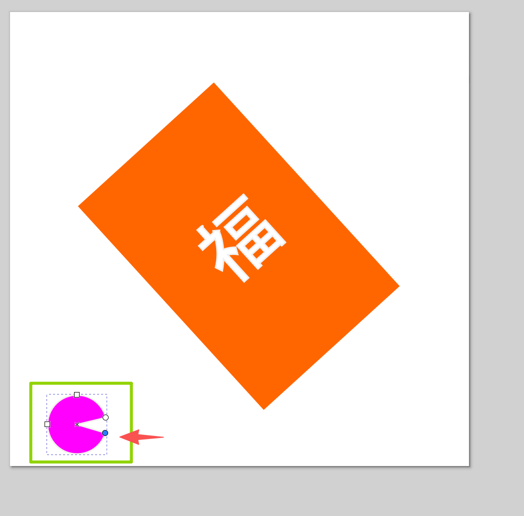
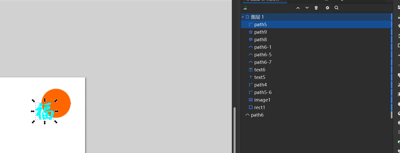
Adding Decorative Circles
I added circles on the sides as decoration. Holding Ctrl while dragging with the Ellipse tool constrains the shape to a perfect circle. I adjusted curves by editing node handles, the small arrows at each control point set the tangent direction of the Bézier segment, so moving them changes how smoothly the curve flows.
I noticed that a thick stroke changes the measured size of a shape in Inkscape, because stroke width extends outside the path boundary by default. For fabrication, I would need to account for this, the laser cuts the path centerline, not the stroke edge.
I also noticed a small gap in one circle's stroke, which can occur when a path is not fully closed. In Inkscape I fixed it using Path → Close Path (Shift+L).
Final Composition
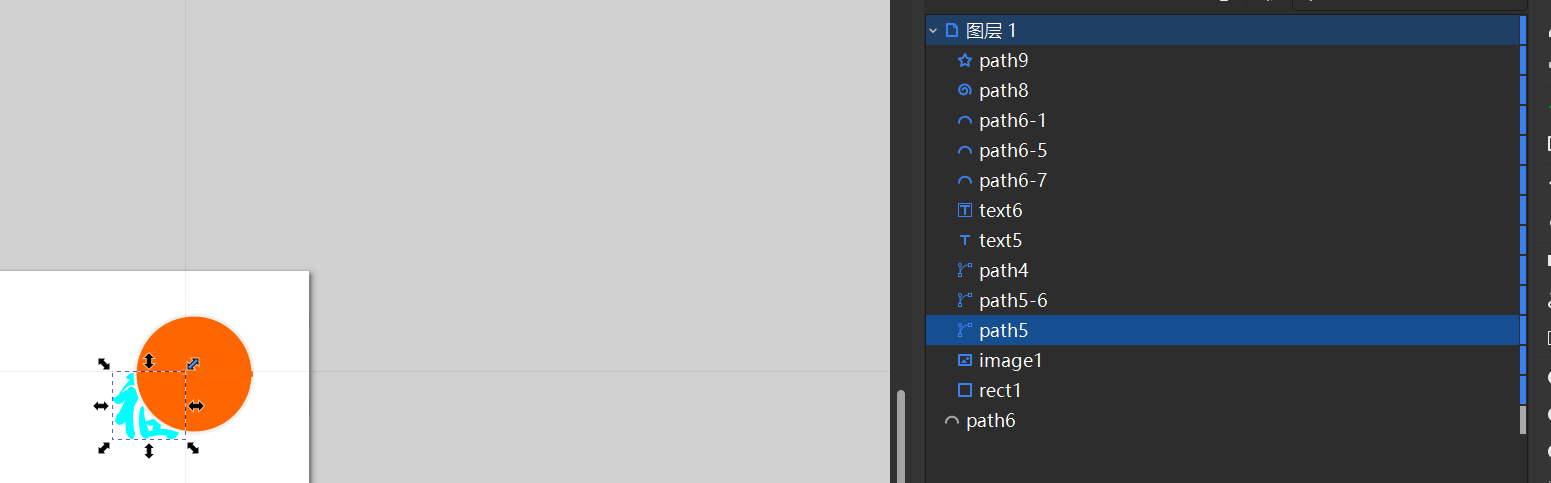
I centered the 福 character between the circular elements. Using the Layers panel, I placed the character on the top layer so it stays visible over the frame geometry underneath.
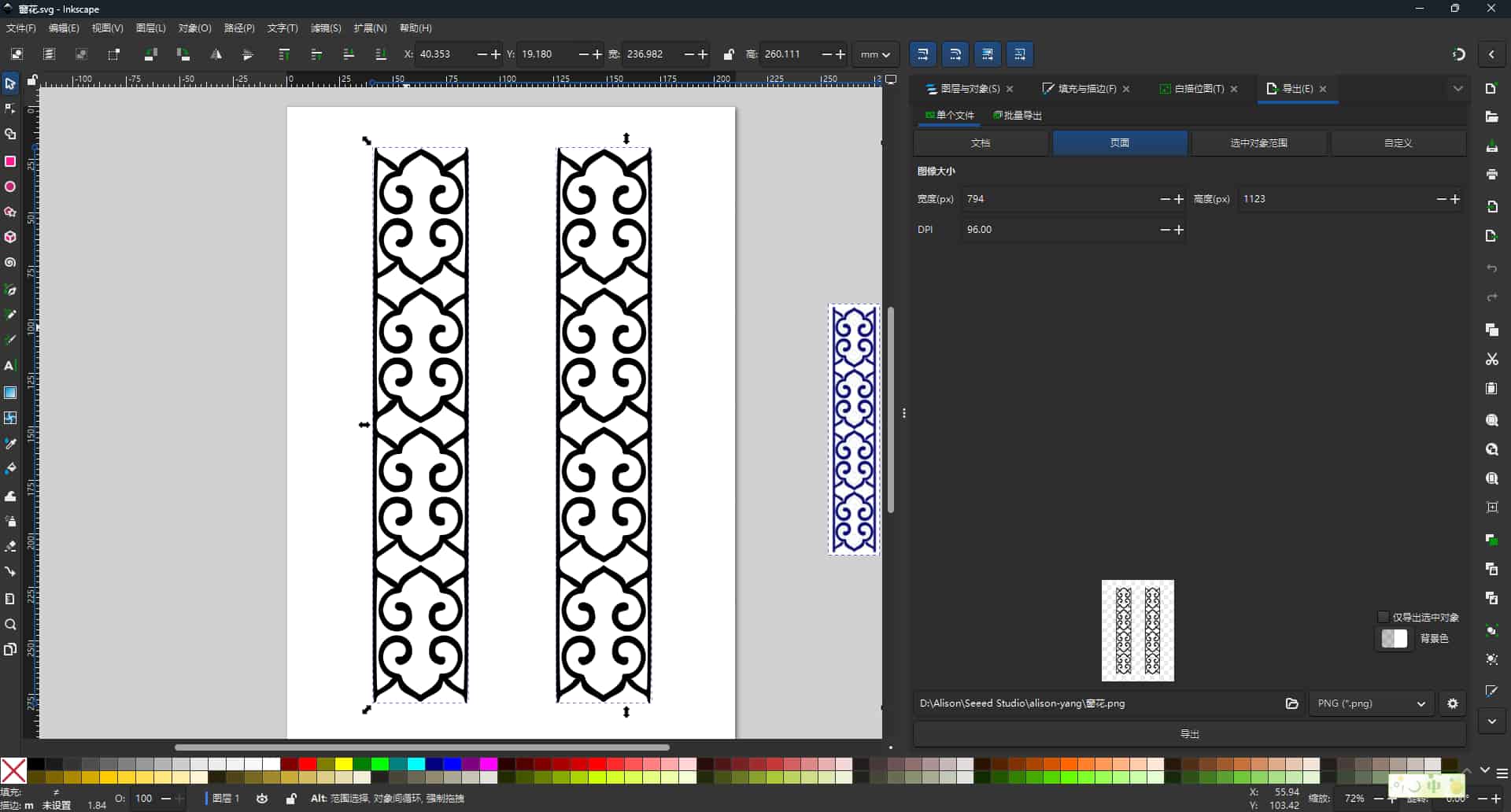
Final result of my first Inkscape design:
I really like the color panel in Inkscape. When designing the final project's frame, I tried to explore this direction:
Understanding Bézier Curves
While working in Inkscape, I ran into Bézier curves repeatedly, they define every path, every font outline, and every smooth shape in vector graphics.
A Bézier curve is defined by:
- A start point and an end point
- Two control handles that pull the curve toward them without the curve passing through them
Moving a handle changes the tangent direction at the anchor point, which changes how smoothly the curve enters and exits. When I manually traced the Fu character, I was placing these points and handles deliberately for every stroke.
This helped me understand why vector graphics can scale infinitely, the math recalculates from the same point coordinates regardless of size.
3D Design: Onshape
Why Onshape
For 3D modeling I chose Onshape, a cloud-based CAD platform. The main advantage is that nothing needs to be installed, it runs entirely in the browser. It also includes version history and collaboration, which fits the documentation-first approach of Fab Academy.
One limitation I found: if the internet connection is unstable, the workflow is interrupted.
3D Concepts: CSG and Sketch-Based Modeling
Before building anything, Sophia introduced us to two core 3D design ideas:
CSG (Constructive Solid Geometry): Complex shapes are built by combining simple primitives (cubes, cylinders, spheres) using Boolean operations:
- Union — merge two shapes into one
- Difference — subtract one shape from another (e.g., a cylinder subtracted from a cube makes a hole)
- Intersection — keep only the volume shared by both shapes
Sketch-based parametric modeling (how Onshape works): You draw a 2D sketch on a plane, constrain it with dimensions, then extrude or revolve it into a 3D solid. Every dimension is a parameter, changing the width of the sketch automatically updates the 3D body.
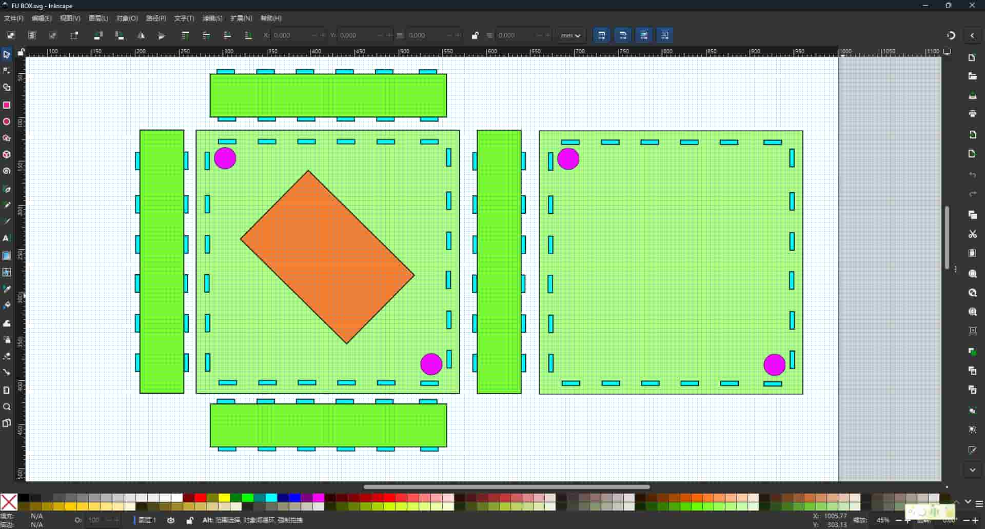
My Onshape Model: Frame Box
I designed a frame structure box in Onshape, the same panel that the 2D Fu design will be mounted on. My goals were: a 300 × 300 mm outer frame, a 120 × 180 mm screen cutout, one hole for a switch, and one decorative cutout.
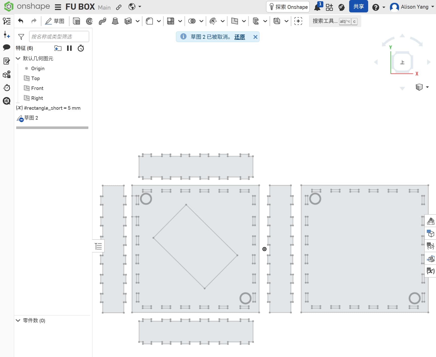
Workflow:
I created a new Part Studio in Onshape and selected the Top plane. I used the Rectangle tool to draw the outer frame at 300 × 300 mm, then drew the inner screen rectangle at 120 × 180 mm, centered on the frame. I added dimension constraints to lock both rectangles to those exact sizes. And I drew some rectangles that fits as slots.
Connecting Design to the Final Project
After working through Inkscape and Onshape, I started applying both tools to my final project ideas. My instructor noted that Onshape is more precise for structural work, while Inkscape is better for decorative surface detail — so the workflow would be: structure in Onshape, decoration in Inkscape, combine for fabrication.
I explored different decoration directions: window-style lattice patterns, sticker-like motifs, and laser-cut cutouts.
This part of the week felt especially meaningful, because I was no longer only learning software functions, I was starting to connect design tools with my own project ideas.
What Did Not Work
- First pen trace attempt: my Bézier points were too far apart, making the curves jagged. I had to go back and add more intermediate nodes to follow the stroke shape accurately.
- Trace Bitmap on a low-contrast image: the automatic trace picked up background noise and produced hundreds of stray nodes. I learned that cleaning up the bitmap in GIMP first (increasing contrast, converting to black and white) produces a much better trace result.
- Onshape on a slow connection: twice during the session the browser disconnected mid-sketch and I lost the unsaved sketch. Onshape now auto-saves more aggressively, but I learned to use Ctrl+S habitually.
Design Files
| File | Format | Description |
|---|---|---|
| fu-panel.svg | SVG | Complete Fu panel — Inkscape source |
| fu-box.dxf | DXF | Exported for laser cutting |
| fu-decoration.svg | SVG | Box decoration |
Summary: What I Learned
- The difference between bitmap and vector graphics, and why it matters for fabrication
- How GIMP and Inkscape serve different stages of the same workflow
- How Bézier curves work and how to edit nodes to refine a traced path
- How to set up and constrain a 2D sketch in Onshape and extrude it into a solid
- How Boolean difference creates holes and cutouts in 3D geometry
- That cleaning up the bitmap input in GIMP before tracing in Inkscape saves significant node-editing time
This week helped me move from casual visual editing toward a more fabrication-oriented way of thinking. For me, that was the most important progress.