Week 9 - Input Devices
Personal Assignment
- Measure something: add a sensor to a microcontroller board that you have designed, and read it.
About the DHT11 Sensor
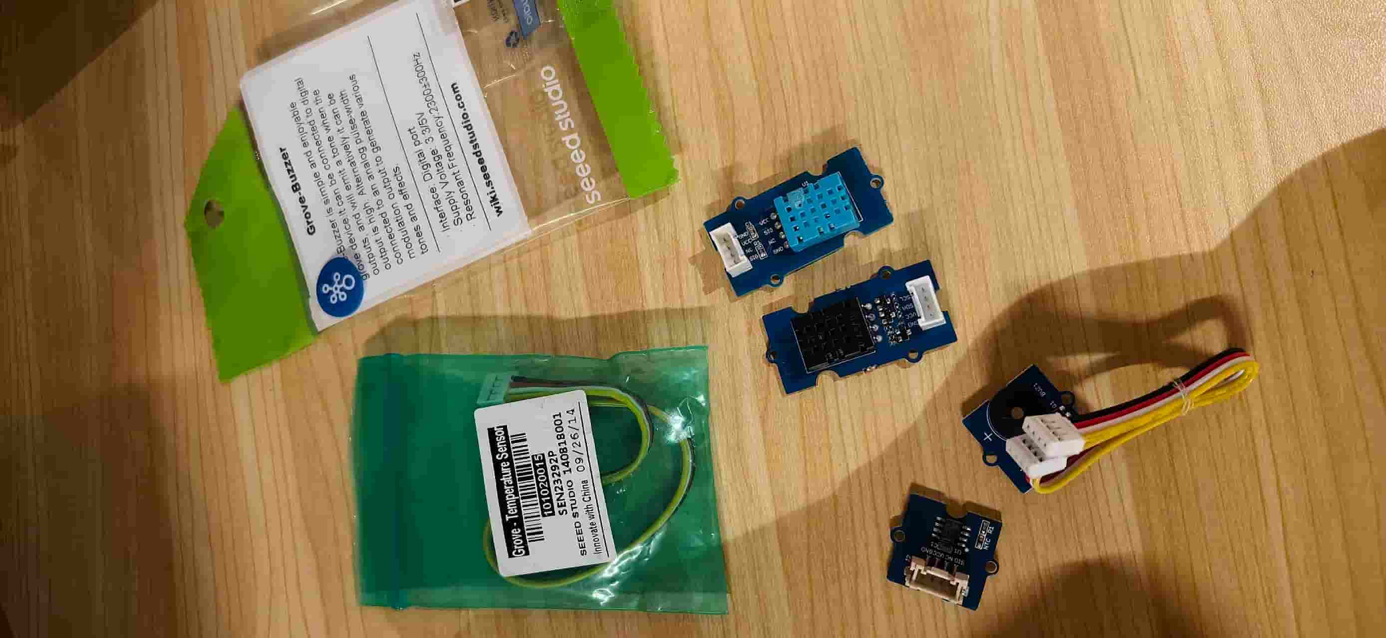
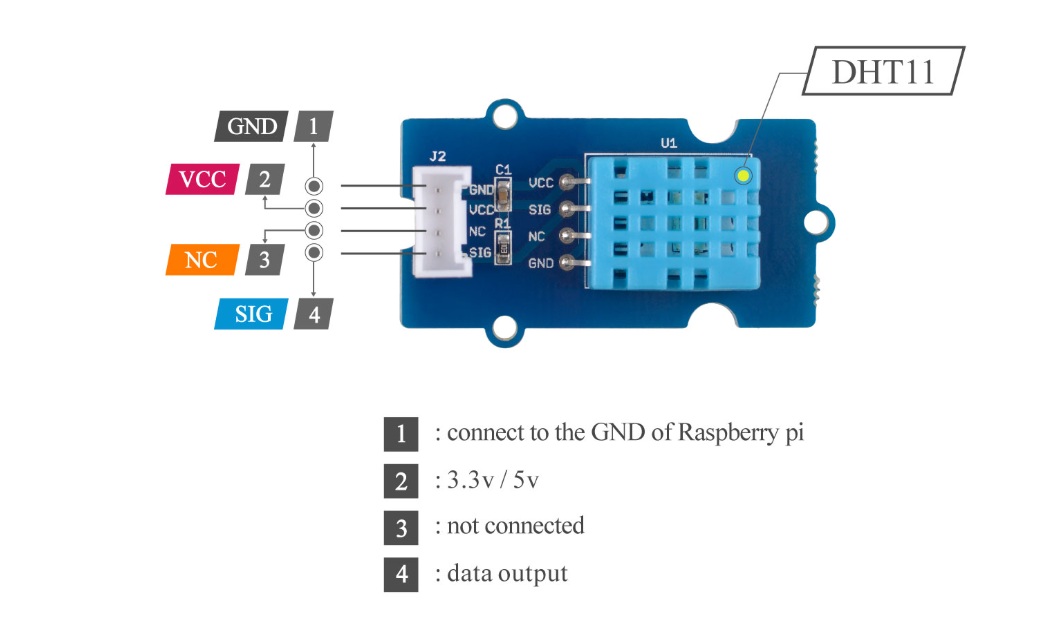
I chose the Grove DHT11 a basic digital temperature and humidity sensor from Seeed Studio, as my input device for this week.
Key Specs
- Measurement range: Temperature 0–50°C, Humidity 20–90% RH
- Accuracy: Temperature ±2°C, Humidity ±5% RH
- Supply voltage: 3.3V–5.5V
- Output: Single-bus digital signal
How it works
The DHT11 has a resistive humidity element and an NTC temperature element inside. When it collects environmental data, it sends a digital signal to the microcontroller through a single-wire protocol. A full data packet is 40 bits: humidity integer, humidity decimal, temperature integer, temperature decimal, and a checksum.
The communication handshake goes like this:
- The host pulls the data line low for at least 18 ms, then releases it high for 20–40 μs.
- The sensor responds with 80 μs low, then 80 μs high.
- Each data bit begins with a 50 μs low pulse. The following high pulse determines the value: 26–28 μs = "0", 70 μs = "1".
Part One: Hardware Connection
Wiring
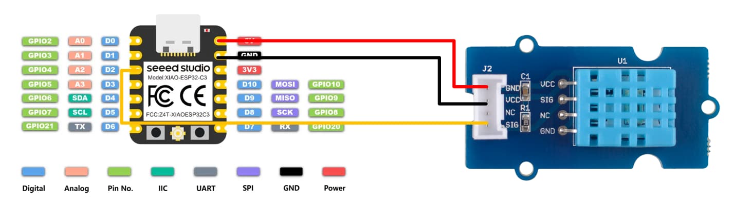
Connect the Grove DHT11 to XIAO ESP32C3:
| Grove DHT11 Pin | XIAO ESP32C3 Pin |
|---|---|
| VCC | 5V |
| GND | GND |
| DATA | D2 |
The wiring diagram is shown below.
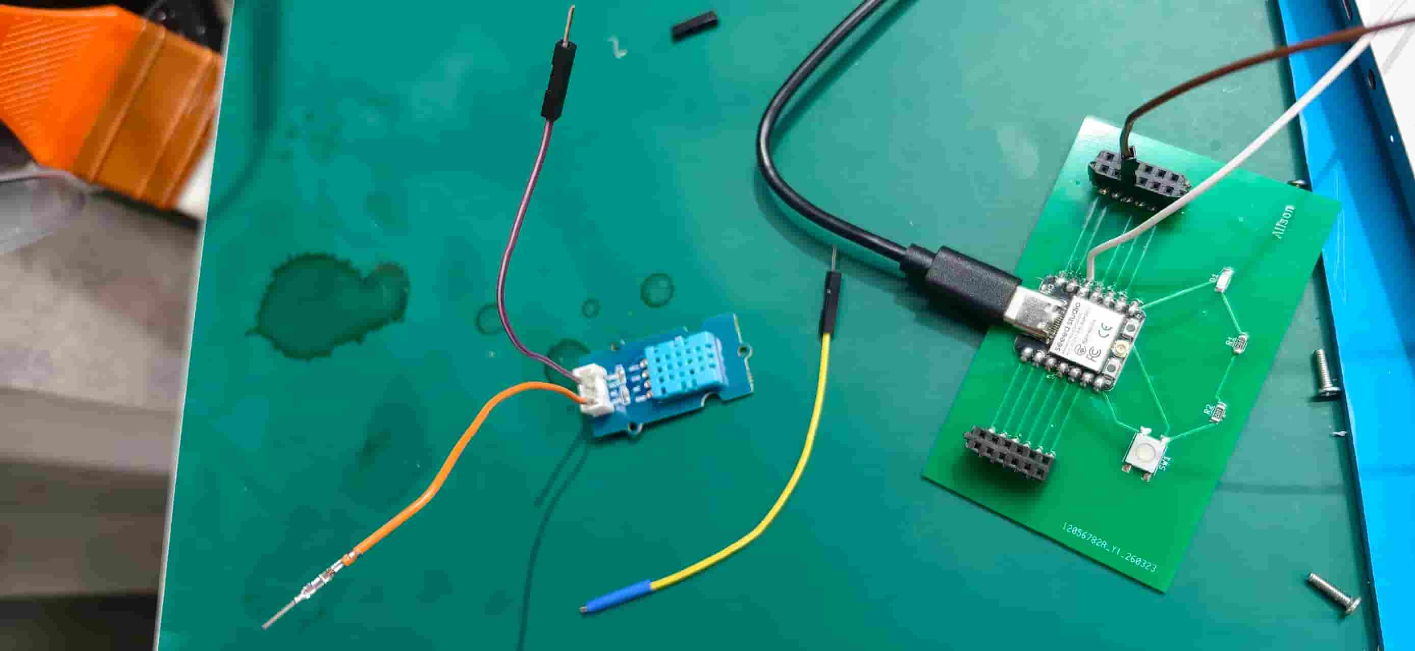
On the bench, the custom Week 8 board, XIAO, and DHT11 looked like this while I was testing connections.
Part Two: Software Setup
Install the libraries
- Open Arduino IDE. Download the Arduino IDE 2.3.8 version.
- Go to Tools → Manage Libraries.
- Search for and install DHT sensor library and Adafruit Unified Sensor.
- Make sure your board is set to Seeed Studio XIAO ESP32C3 under Tools → Board.
Code
#include "DHT.h"

#define DHTPIN D2
#define DHTTYPE DHT11

DHT dht(DHTPIN, DHTTYPE);

void setup() {
  Serial.begin(9600);
  Serial.println("DHT test");
  dht.begin();
}

void loop() {
  delay(2000);

  float h = dht.readHumidity();
  float t = dht.readTemperature();

  if (isnan(h) || isnan(t)) {
    Serial.println("Failed to read from DHT sensor!");
    return;
  }

  Serial.print("Humidity: ");
  Serial.print(h);
  Serial.print("%  Temperature: ");
  Serial.print(t);
  Serial.println(" C");
}
Upload
- Select Tools → Board → Seeed Studio XIAO Series → Seeed Studio XIAO ESP32C3.
- Select the correct COM port under Tools → Port.
- Click Upload.
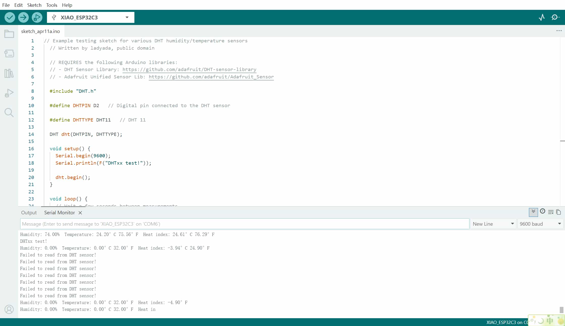
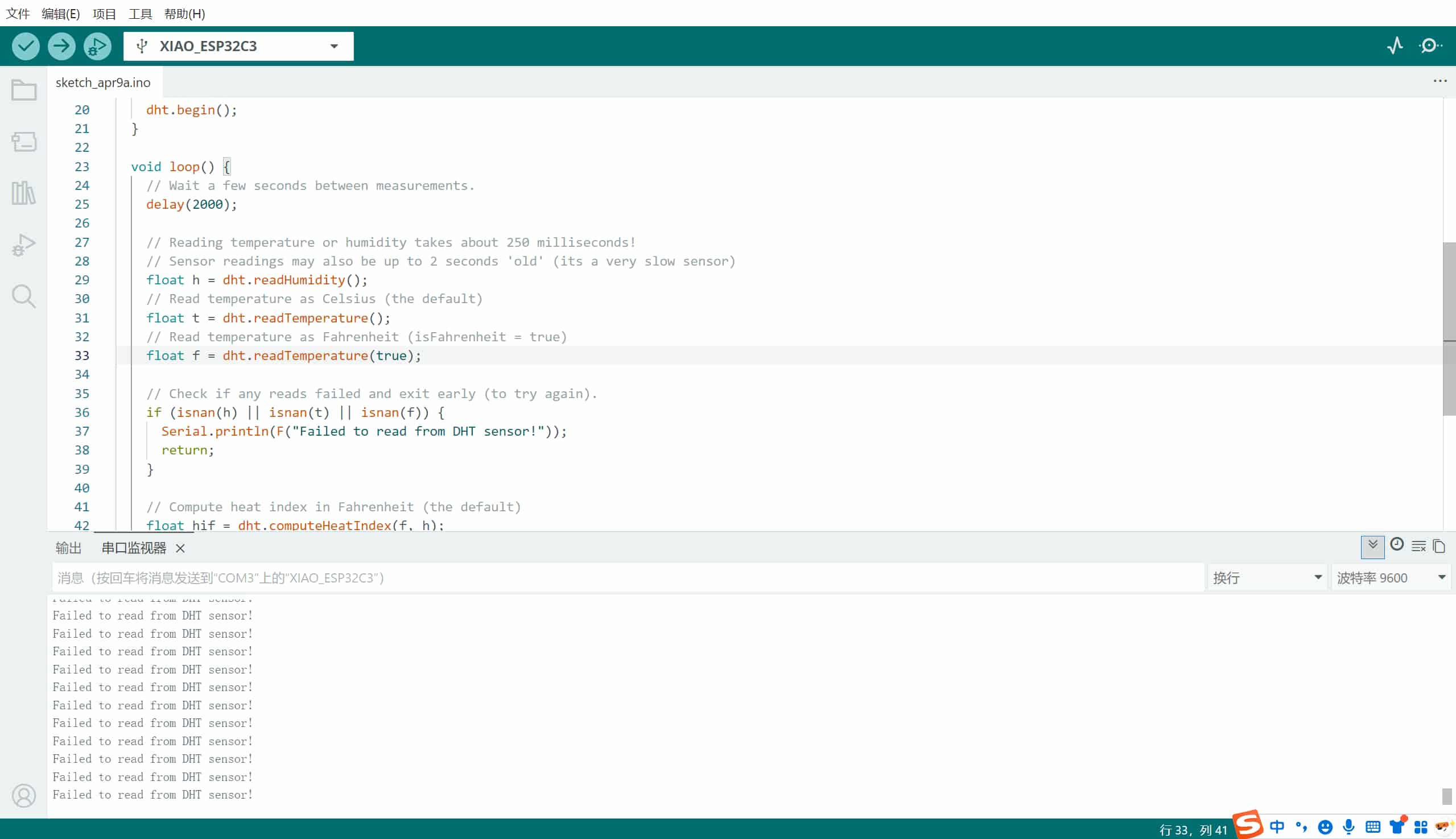
If everything is connected correctly, I should see temperature and humidity values updating in the Serial Monitor every two seconds. But the progress was far more difficult than I thought: early runs jumped between good readings, zeros, and repeated “Failed to read from DHT sensor!” messages.
Downloadable sketches
- DHT11 readout on D2 (matches the sketch above)
- DHT11 + buzzer on expansion shield (D0/D1)
- DHT11 with OLED screen (U8g2)
Part Three: The (Very Long) Road to a Working Reading
This week was honestly one of the most frustrating so far. I ran three separate rounds of testing before I finally got a clean, stable reading. Here is what actually happened.
Round 1 — The JLCPCB Board
My first attempt was on the custom PCB I had made in Week 8 (ordered through JLCPCB). I tried both the DHT11 and the DHT20, connected through jumper wires, and both failed. The readings were either wildly wrong or just not showing up at all.
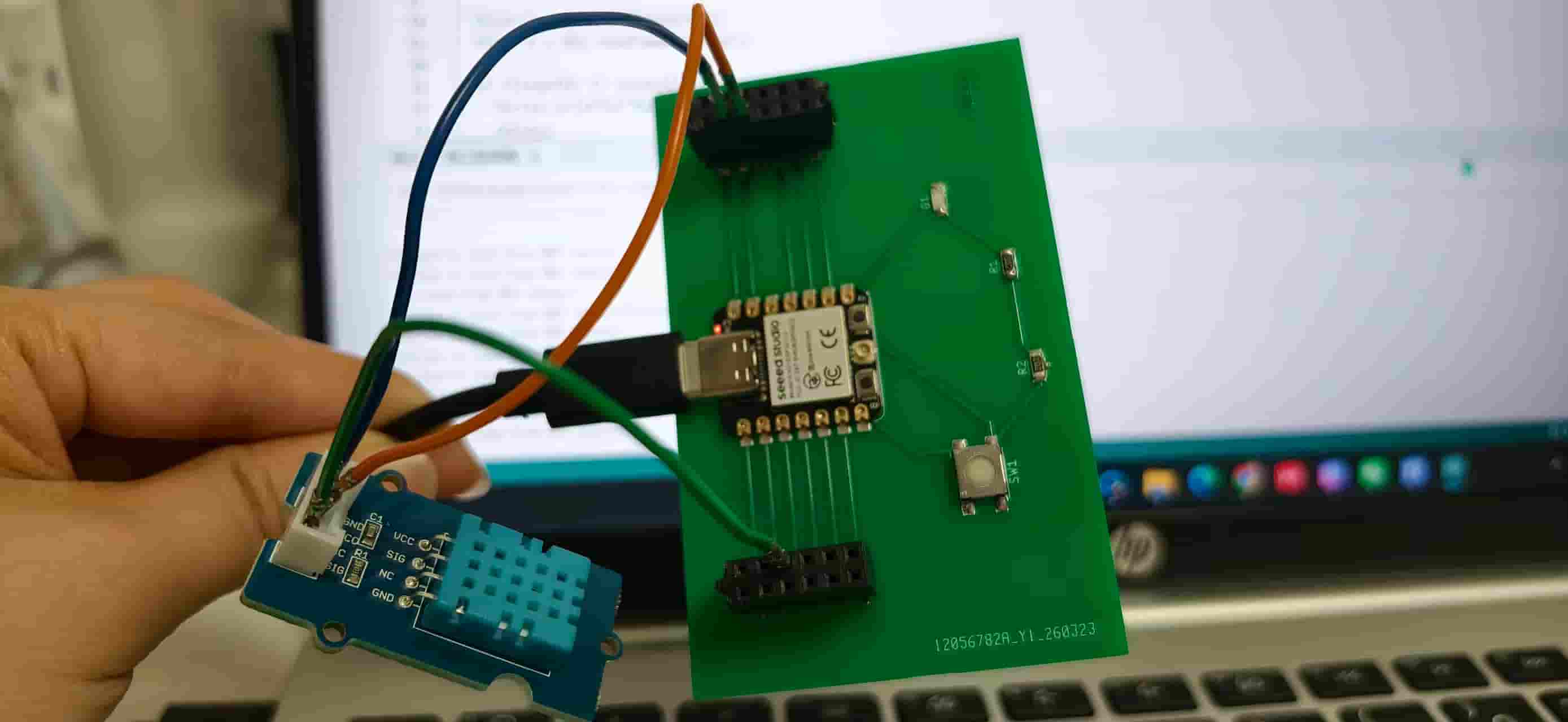
I spent a long time suspecting the code, re-checking wiring diagrams, wondering if the board was somehow damaged. It turned out the answer was much simpler and much more embarrassing: I had been connecting the GND wire to the wrong pin the entire time. On the Grove DHT11, GND is the third pin, not the second. I had been consistently plugging into pin 2. Since I designed 5V to the first pin, the second pin should be GND, but I forgot that I routed it to the third pin, and the socket is vertical, which hides the labels from a casual glance.
A colleague finally pointed it out; once I looked properly, I could not believe I had missed it.
Even after fixing the pin, the readings were still unstable. At that point I also wondered if maybe the DHT modules themselves had problems.
Round 2 — Adding a Wire, More Suspicion
I thought the issue might be with the 5V power supply on my board, so I tried routing a separate wire to bring out a different voltage source. It did not really help. The readings were still inconsistent, and I started to wonder whether the board had been burned at some point.
It had not, but I would not confirm that until later.
On April 11, I picked up a brand new DHT module to try again. I still had problems: the temperature reading went to more than 600° (clearly nonsense).
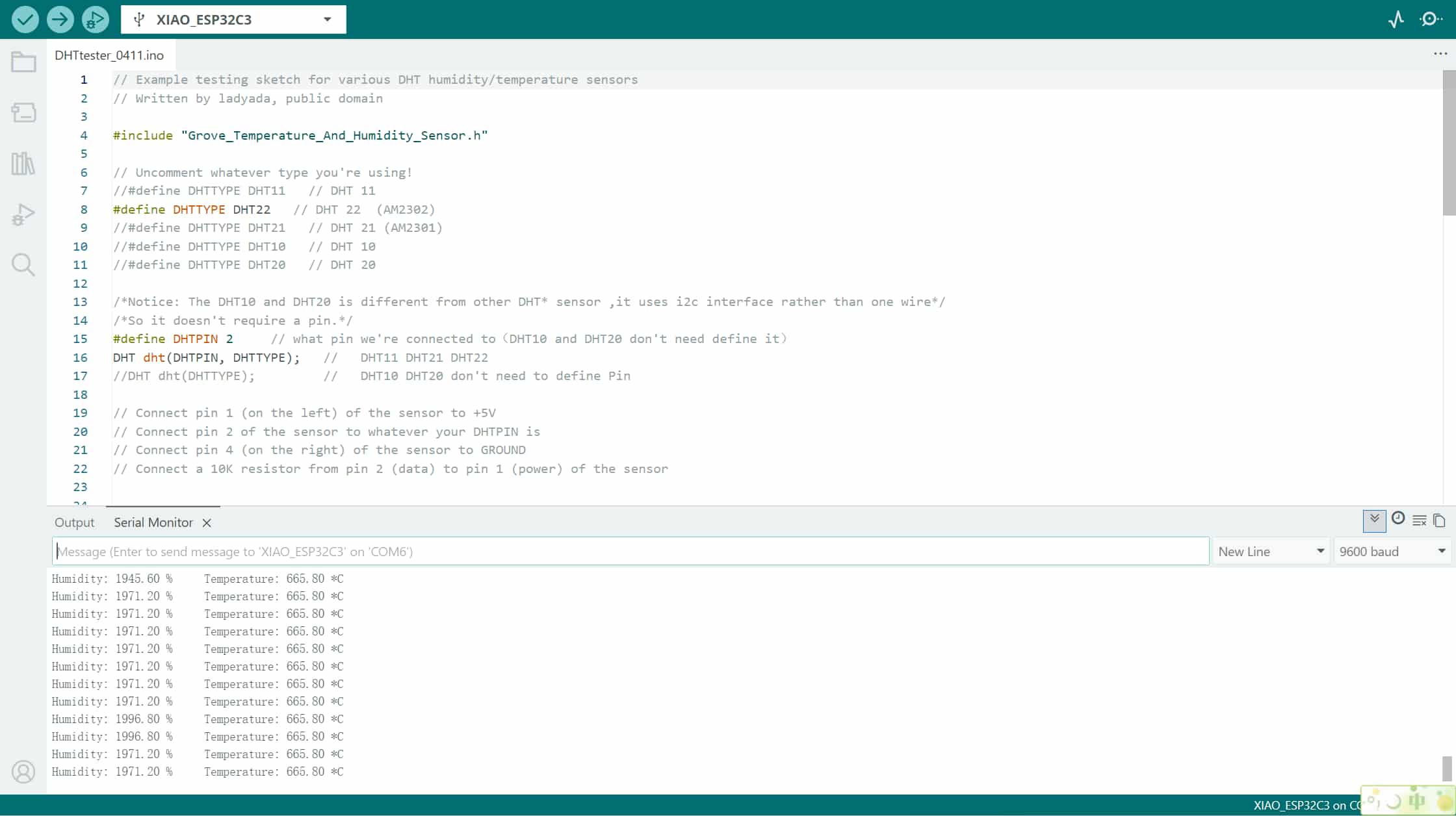
Then I looked more carefully at my PCB schematic and found another problem: when I originally drew the schematic, I had placed the 3.3V connection at the position of a switch, not an actual external socket. The 3.3V line had never been properly broken out. I had to manually solder a short jumper wire to fix it, then connect the sensor through that.
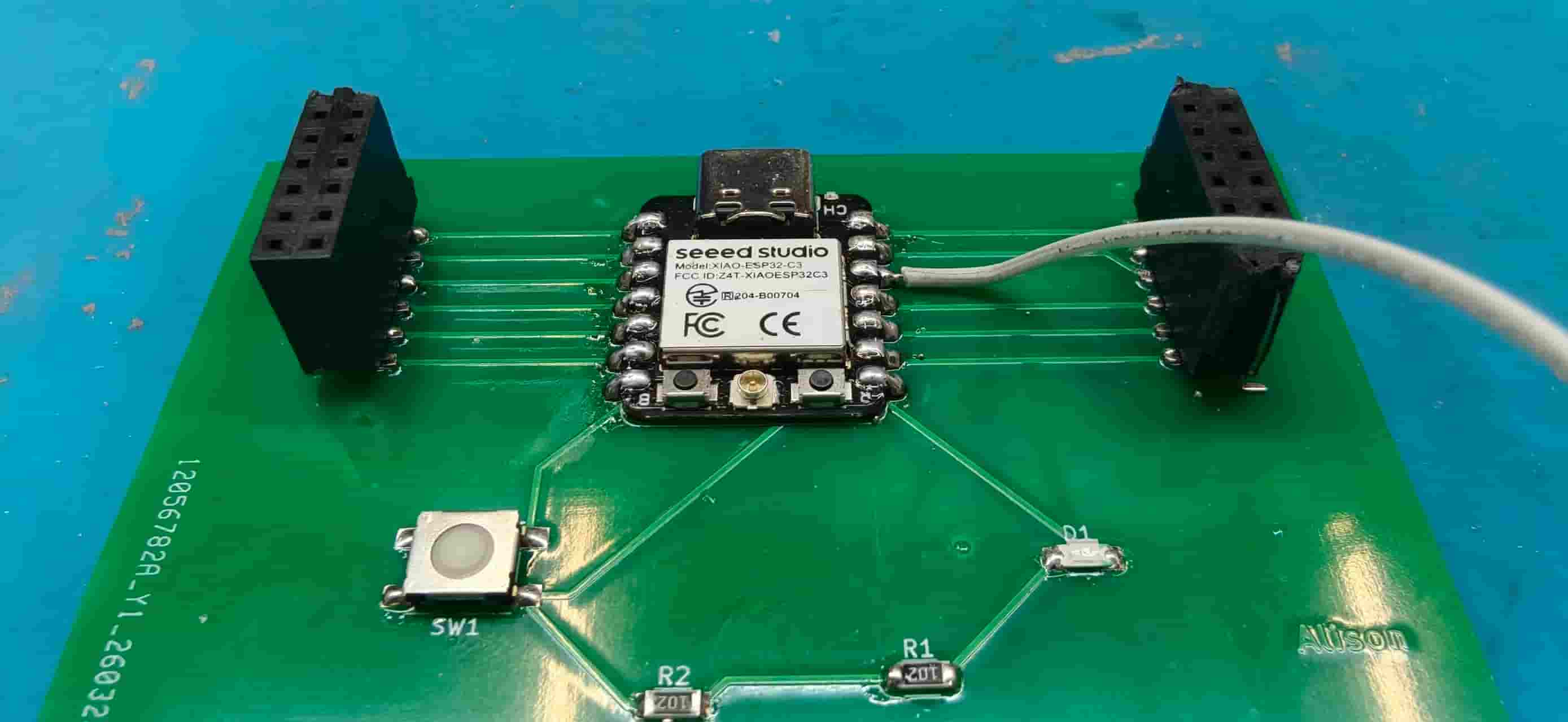
After another full day of trying, the readings finally appeared on screen, and I forgot to take a photo. Very unfortunate.
I changed a little bit of the code to make it run more smoothly:
#include "DHT.h"

#define DHTPIN D2          // 如果你用的是 D2 / D02 这个引脚
#define DHTTYPE DHT11

DHT dht(DHTPIN, DHTTYPE);

void setup() {
  Serial.begin(9600);
  delay(1000);
  Serial.println("DHT11 test start");
  dht.begin();
}

void loop() {
  delay(2000);

  float h = dht.readHumidity();
  float t = dht.readTemperature();

  if (isnan(h) || isnan(t)) {
    Serial.println("Failed to read from DHT sensor!");
    Serial.println("- Check wiring: VCC/GND/DATA");
    Serial.println("- Add 4.7k pull-up on DATA → VCC");
    return;
  }

  Serial.print("Humidity: "); Serial.print(h);
  Serial.print(" %   Temperature: "); Serial.print(t);
  Serial.println(" °C");
}
Round 3 — XIAO Expansion Shield Test
To rule out whether the code was the issue, I tested with a XIAO expansion board (shield) instead of my custom PCB. I plugged in several input modules, including a buzzer, RGB LED, and DHT11.
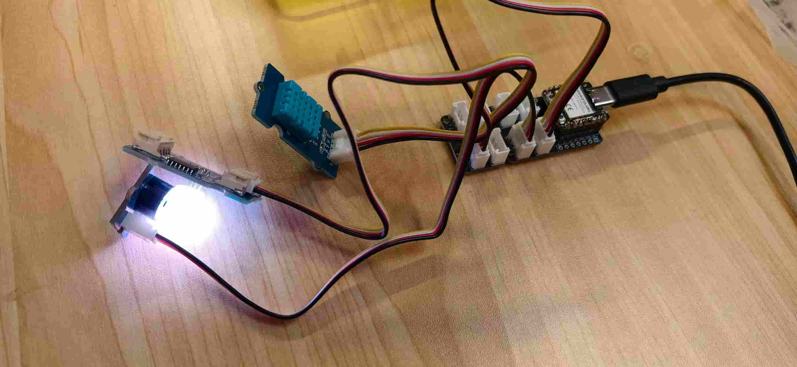
The buzzer and LED behaved strangely: the RGB LED only showed green the very first time, and after that it kept showing pink or white, which was not what I expected. I guessed it might be a pin mismatch on the shield. While I was trying to get the chainable RGB example to compile, the IDE also complained about missing headers even right after installing the Grove Chainable RGB library — another layer of confusion.
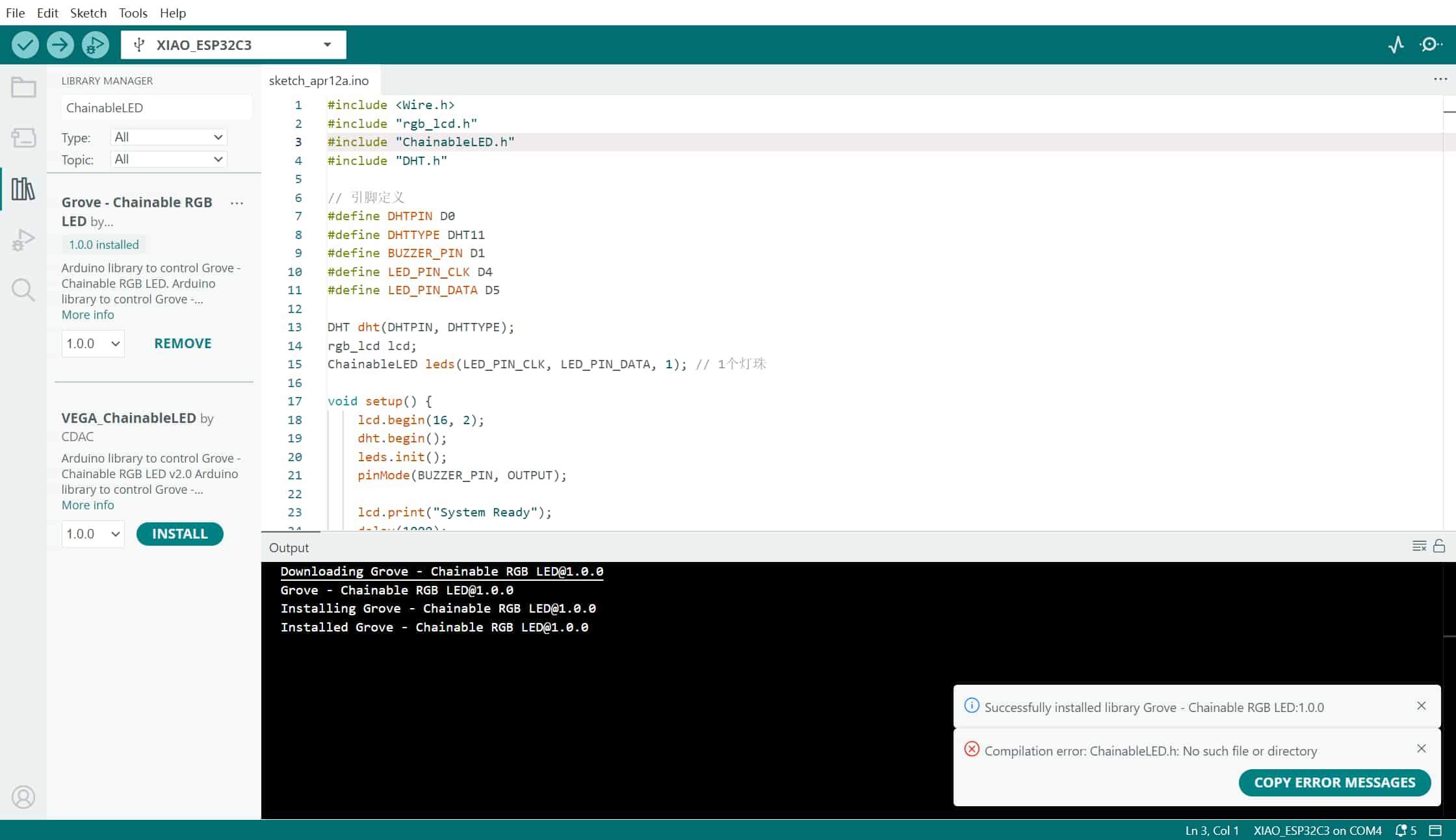
The Grove LED strip driver board I had on hand uses a P9813-style interface (clock and data), which is easy to mix up with other RGB examples if the pins or libraries do not match the shield layout.
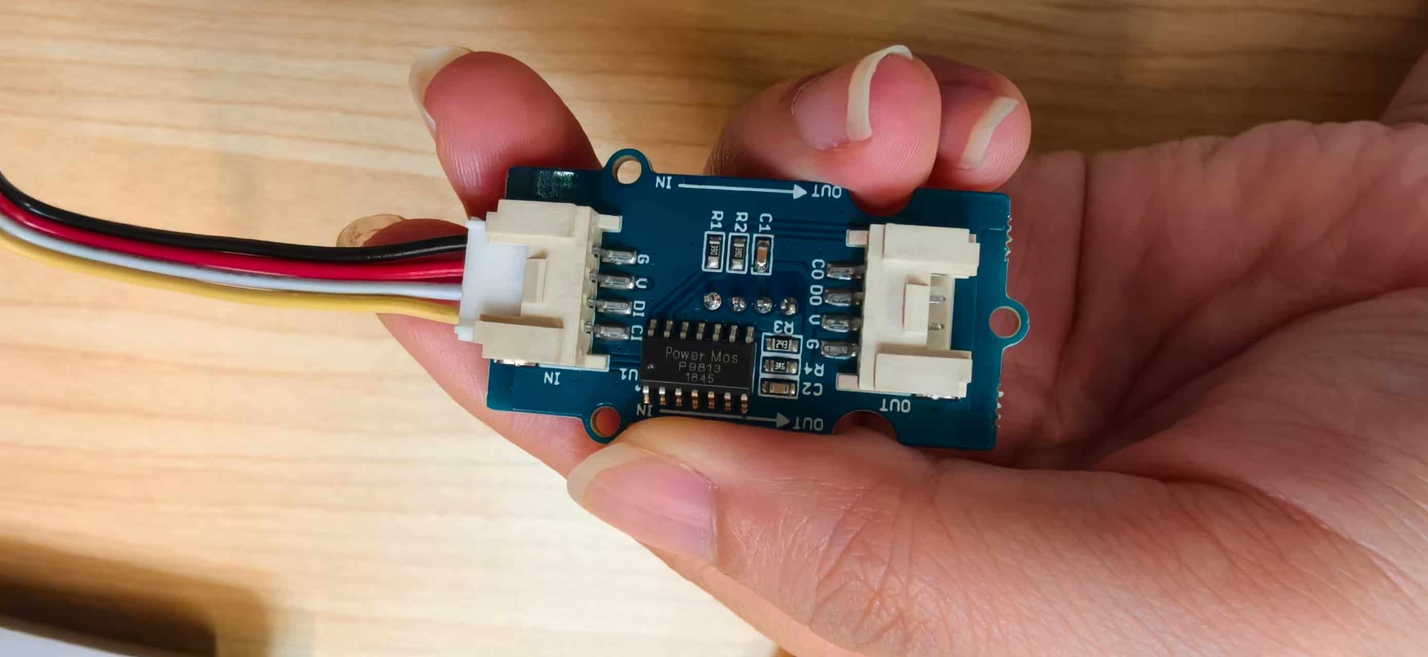
But the DHT11 read temperature and humidity correctly on the shield, which confirmed the code was fine. The Grove connector is really convenient to use. The problem had been on the hardware side all along.
Round 4 — Own PCB, Finally
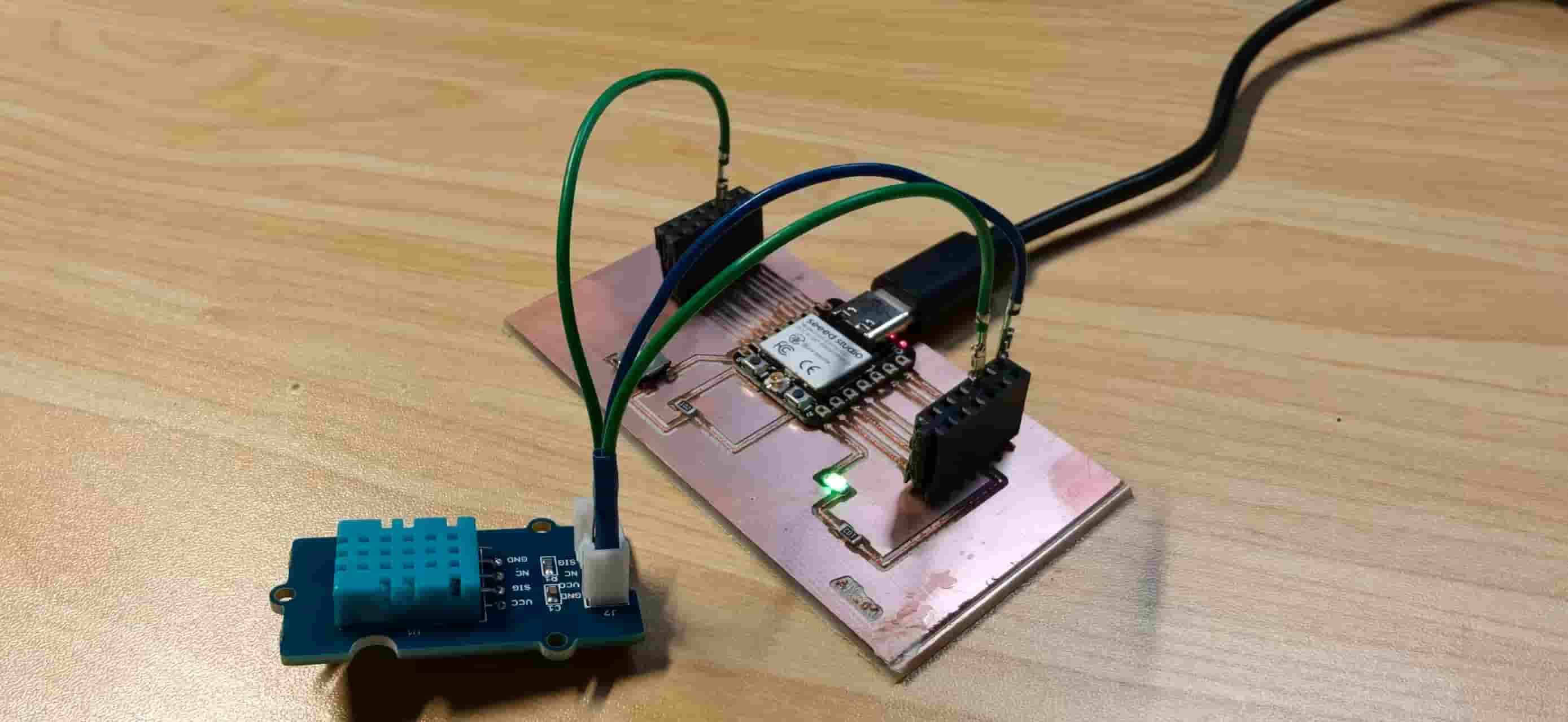
With the shield confirming the code worked, I moved to my own fabricated PCB (PCBA'd from Week 8). I connected the DHT11 with jumper wires again and ran the test.
The first attempt still failed. I looked at the wiring and found I had plugged D2 into D0 by mistake. Fixed that. Then I decided to use the 5V pin instead of 3.3V.
Once I pressed that wire back into contact and held everything in place, the Serial Monitor finally started showing reasonable numbers: temperature and humidity both within a sensible range, updating steadily.
The same bring-up rig used the DHT11 together with the buzzer on the custom board — messy jumpers, but finally the right pins.
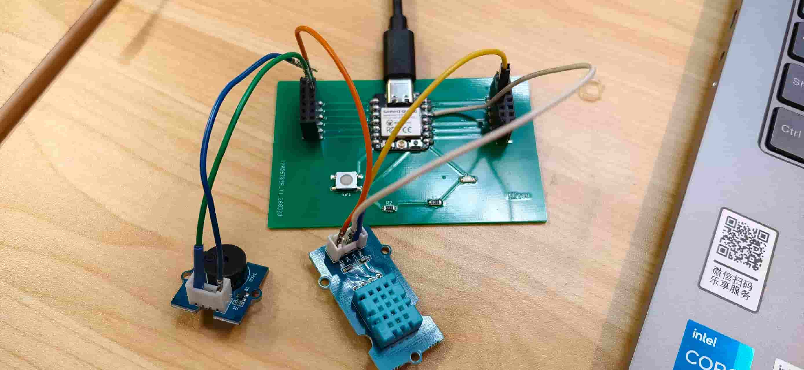
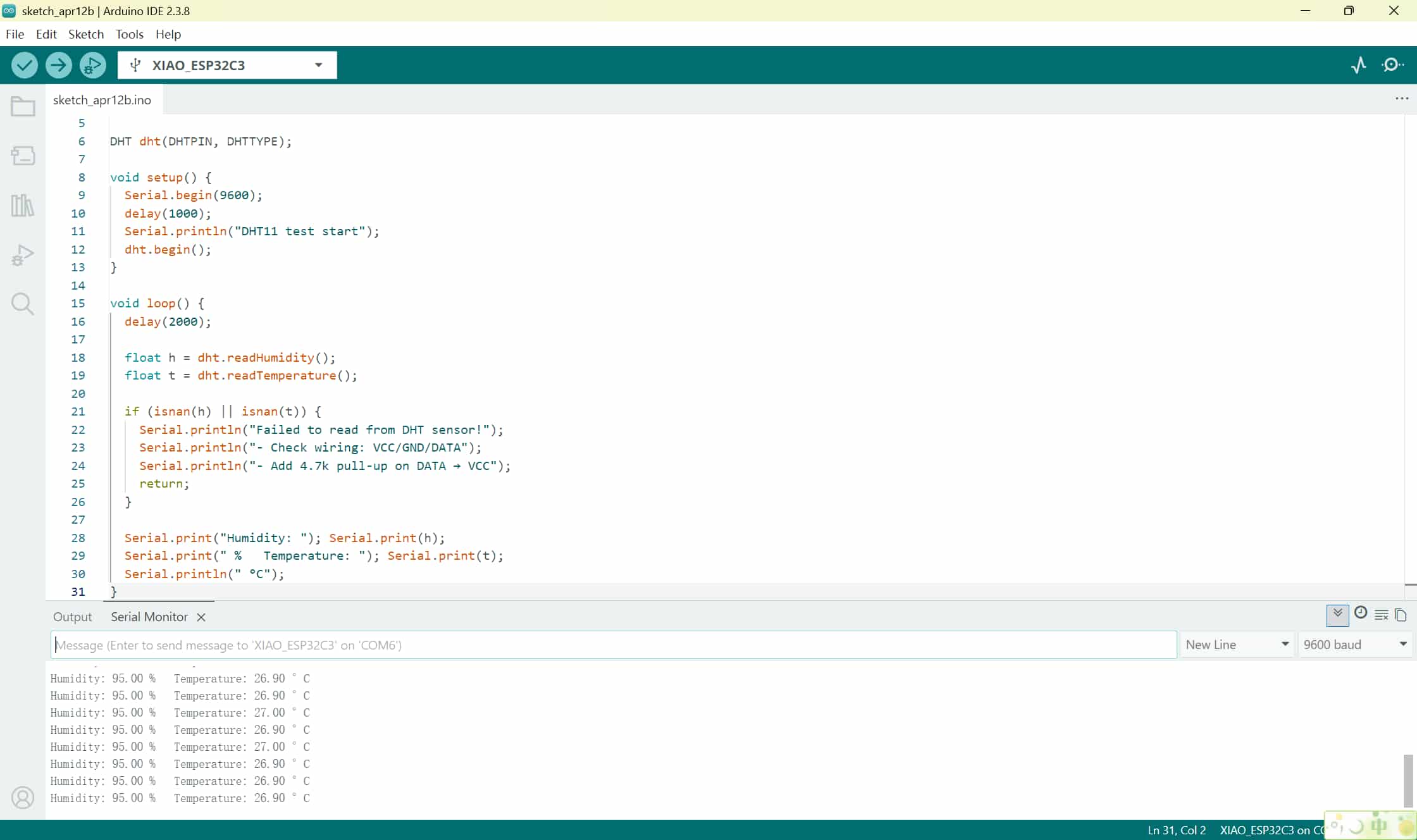
It worked! I was so proud of it.
Recap
Here is the short version of what went wrong and how it got fixed:
| Round | Setup | Problem | Fix |
|---|---|---|---|
| 1 | JLCPCB PCB + DHT11/DHT20 | GND connected to wrong pin (pin 2 instead of pin 3); also tried DHT20 | Colleague pointed out the pin error |
| 2 | Same PCB, extra wire | 3.3V was never broken out as an external socket in the schematic | Soldered a manual jumper; also swapped in a new DHT module |
| 3 | XIAO Shield | RGB LED showing wrong colors; not sure of exact cause | DHT11 read correctly — confirmed the code was not the issue |
| 4 | Own fabricated PCB | D2 plugged into D0; 3.3V jumper loose | Corrected the pin; pressed the wire back into contact |
Reflection
- Read the pinout before you wire anything. I lost a full day because I assumed GND was pin 2 when it is pin 3. Five seconds with the datasheet would have saved that.
- Check your schematic, not just your code. The code was fine from almost the beginning. The real problem was a missing 3.3V socket in my own PCB design — something I had never caught during review.
- Jumper wires lie. A connection that looks seated is not always making contact. Wiggle everything before blaming software.
- Use a test rig before committing to your custom board. Testing on the shield first and confirming the sensor worked there saved me from chasing ghosts in the code.
- Take a photo when something works, even if it is not pretty. I will not make that mistake again.