Week7 - Computer-Controlled Machining
Files
See also the Week 7 group assignment for machine setup, feeds, and safety notes.
Individual Assignment
● Design an object at the meter scale (can be furniture, structural parts, installation art, etc.).
● Machine the parts using CNC (may require machining in multiple pieces if the machine's working area is not large enough for one solid piece).
● Assemble: Join the pieces together to form the whole, considering connection methods (mortise and tenon, screws, glue, etc.).
Motivation
I have a small chair next to the shoe cabinet. I usually sit there while I take off my shoes and rest for a moment with my cat.
After we learned about computer-controlled machining, I thought I could design another small chair to place beside it to my cat, so he could sit nearby next time when I take off shoes.
Tools and software
- CAD: OnShape (free; I had already tried it, so it felt easier than other options).
- Machine: Computer-controlled CNC (sheet cutting and assembly, see group assignment for speeds, feeds, and tooling).
Learning resources
I followed these tutorials before drawing my own parts:
Design process
First try
I first modeled something like a small desk; it was almost a chair in one solid piece.
When I finished, I felt it was not a good fit for CNC: it was more suitable for 3D printing (one volume, not flat parts cut from a sheet).
Thanks to a reminder from designer colleagues, I understood that I needed to split the design into separate parts and assemble them after cutting. So maybe this one is not good for real cutting.
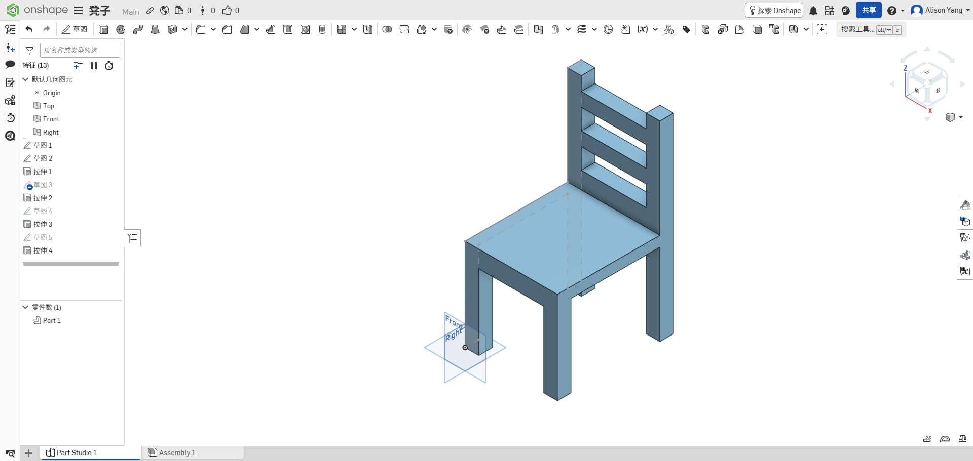
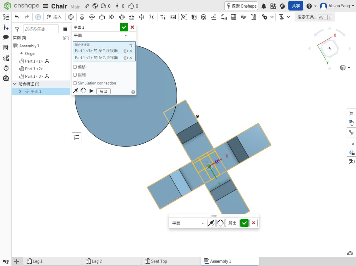
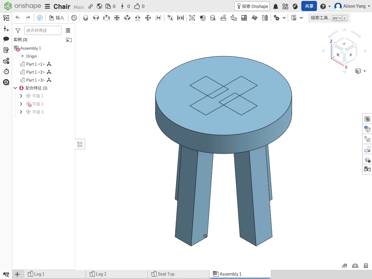
Second try
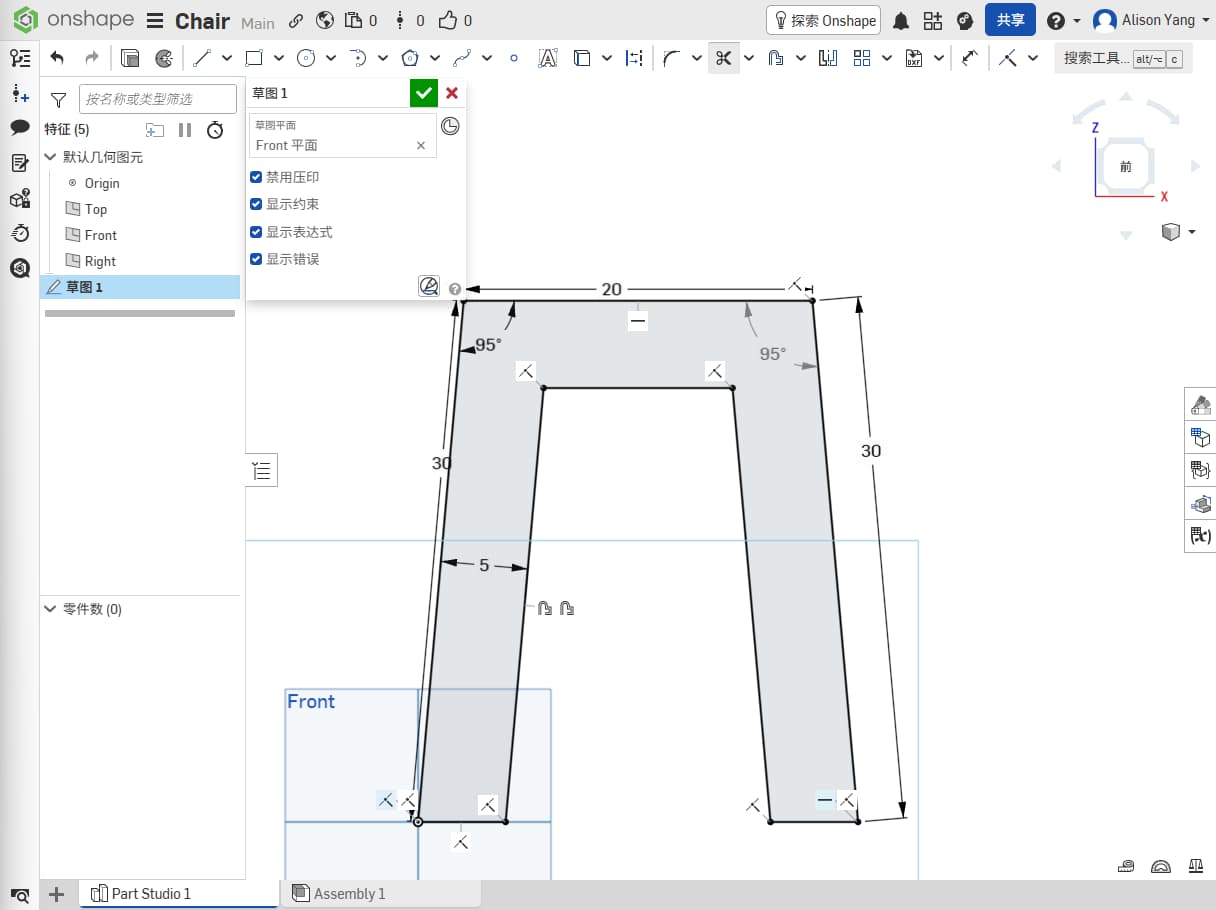
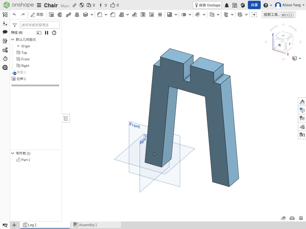
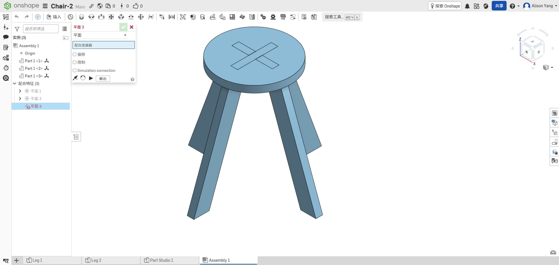
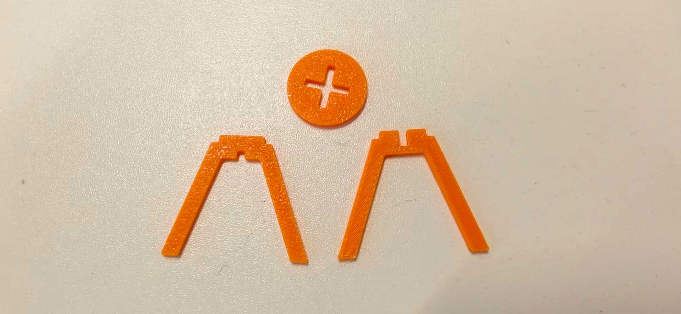
I moved to a simpler structure: three part types, two legs as one piece (a pair), so I need two such pieces, plus one top (seat).
I set the first piece of chair leg thick is 5cm, length for 30cm, top with 2cm to support the top seat. And I extrude for 5cm.(really strong)
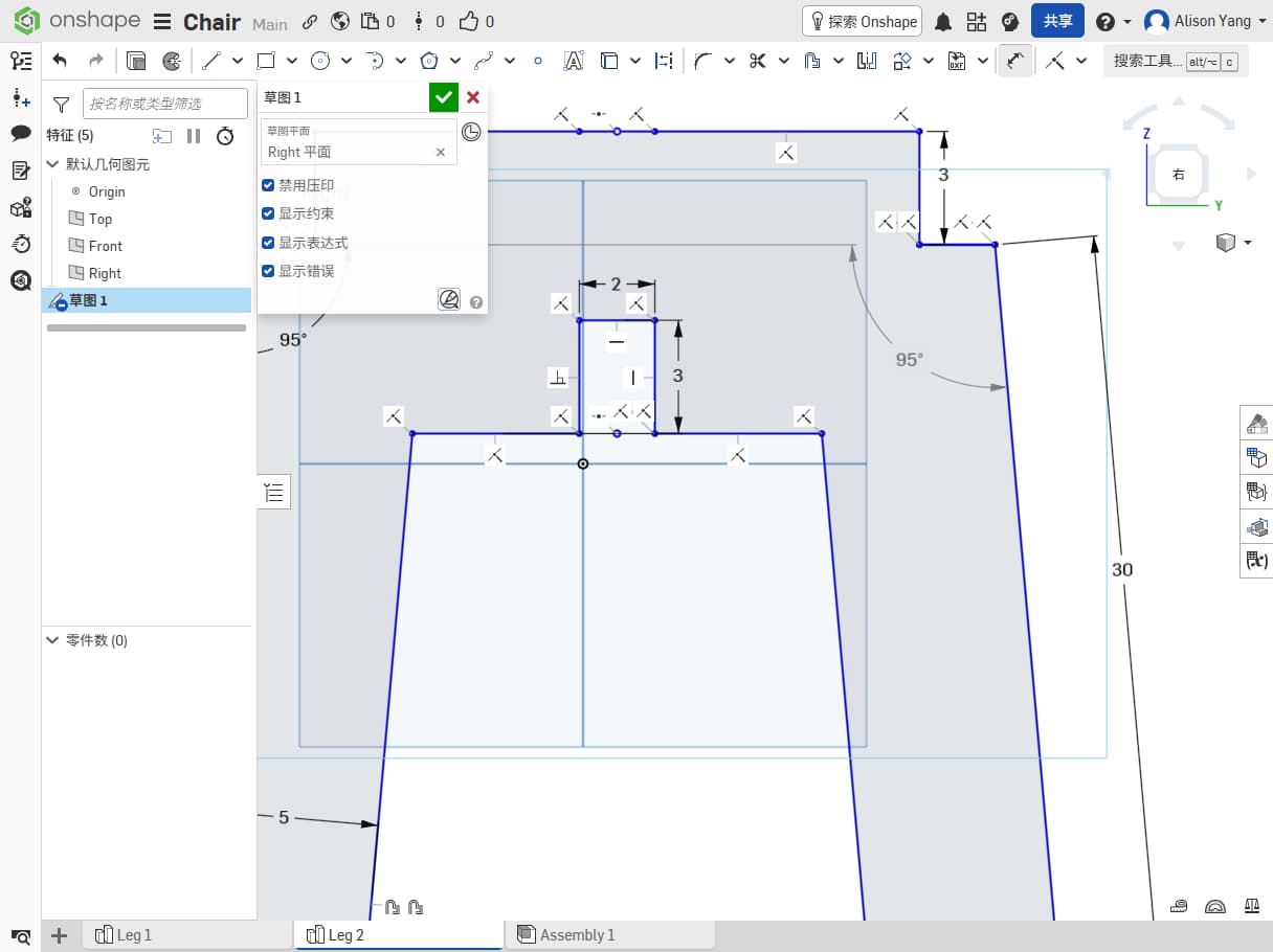
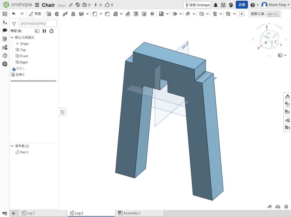
Then, for the second one, I just copy the first leg and adjust the groove design from the top to the bottom.
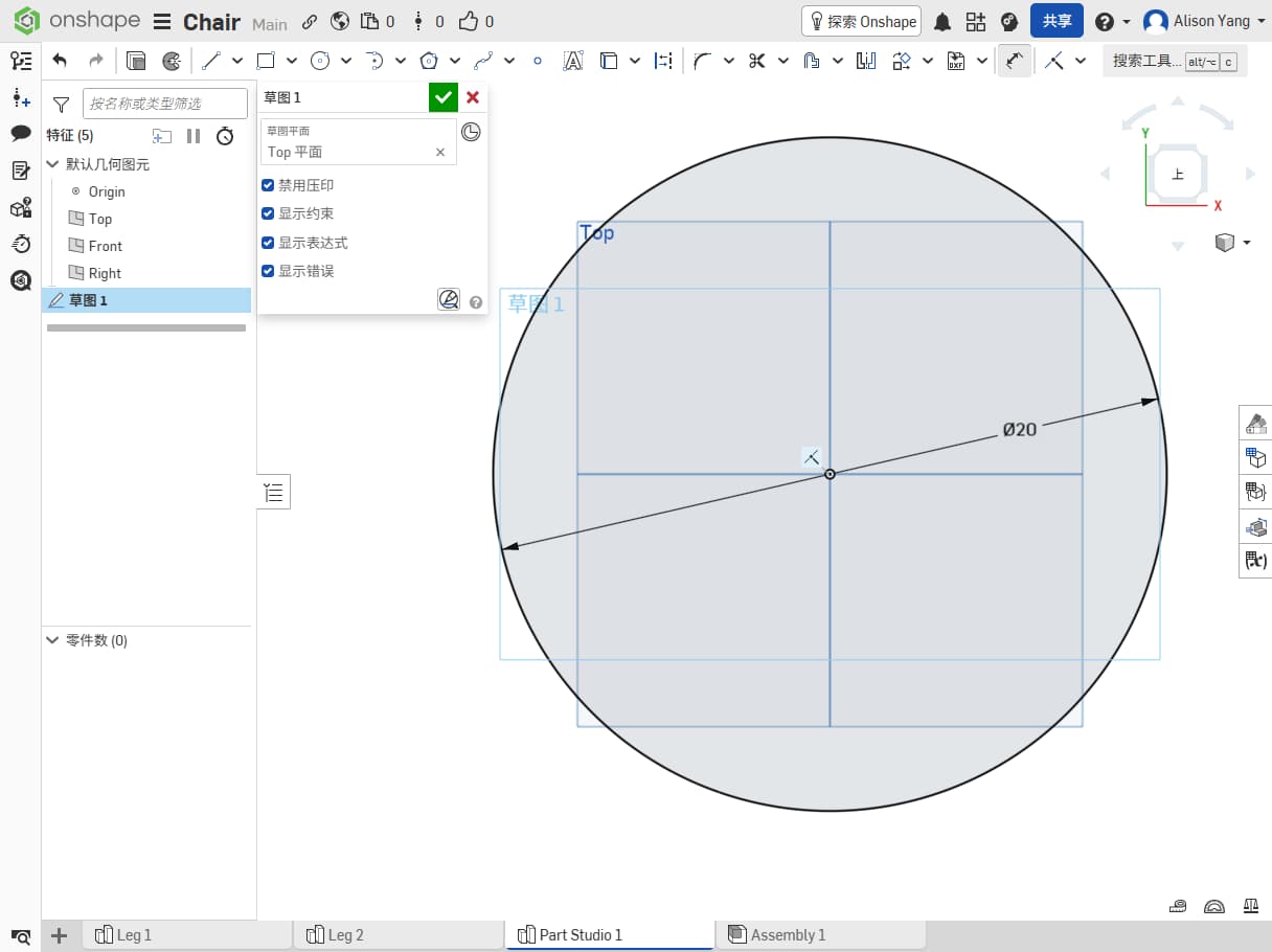
Finally I design the seat top surface, set the diameter for 20cm.
The second time, I designed mostly from feeling and imagination.I wanted it thick so it would feel strong enough to sit on, and cute so I would enjoy looking at it.
I did not think enough about how thick of the material, and the groove needs to be strictly fit for the top, what I designed, didn't consider about it.
The design looked nice on screen, but it would have been hard to make in practice. I did not account for cross / lap joint lengths or fit between parts. That attempt did not work. I did not fully see the problem until a colleague pointed it out, that was my second mistake.
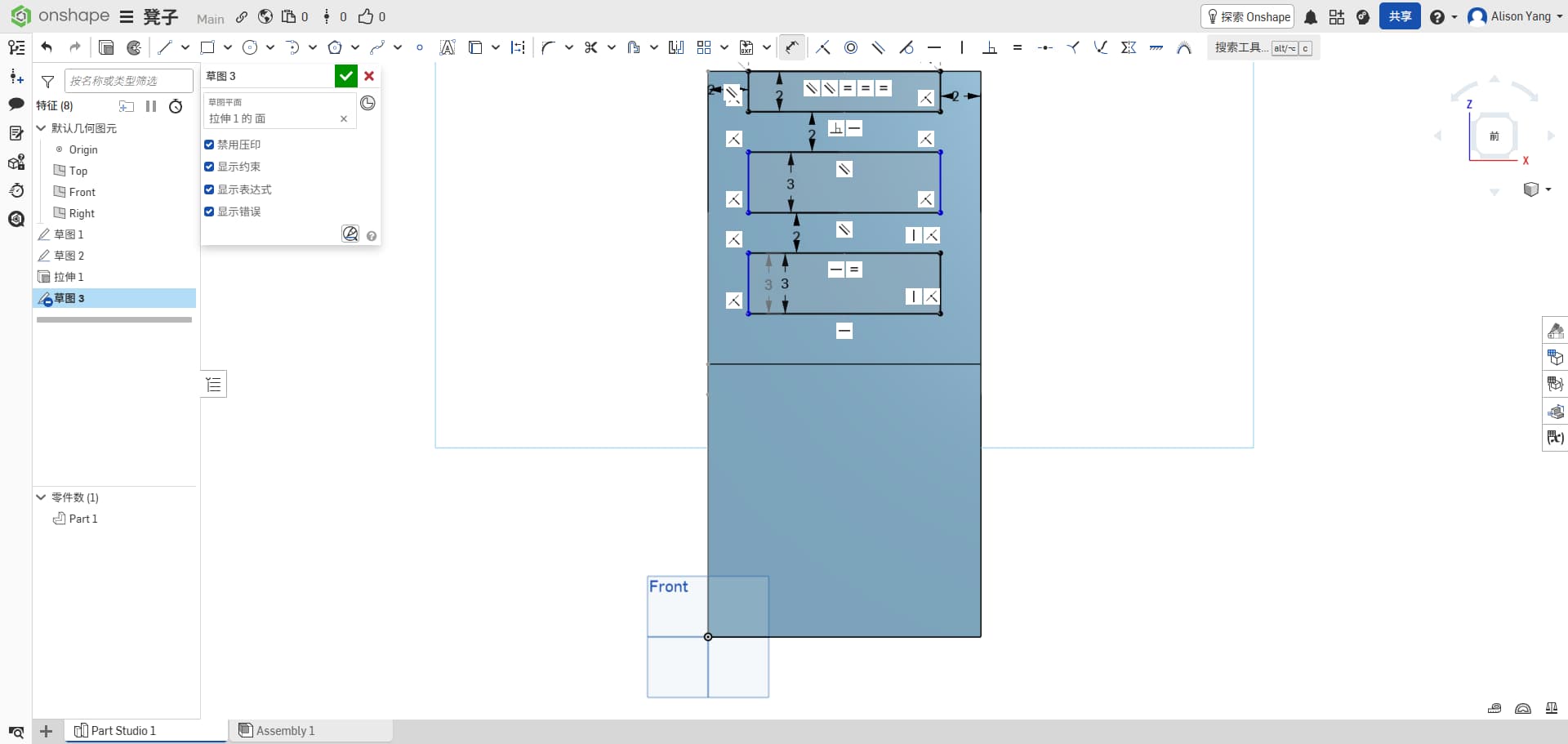
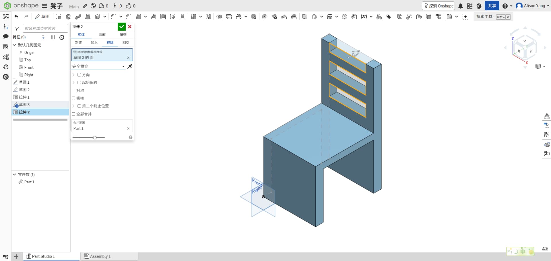
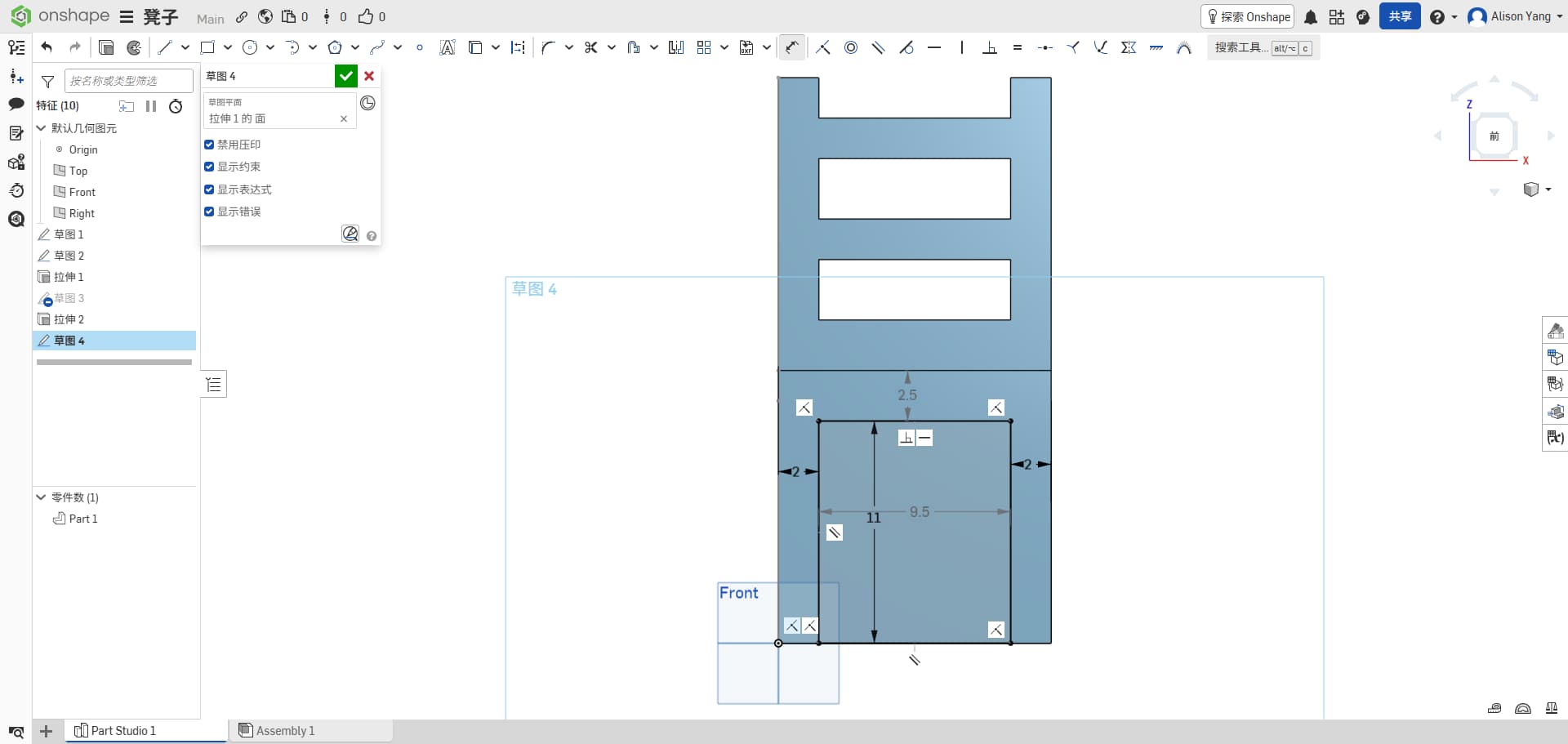
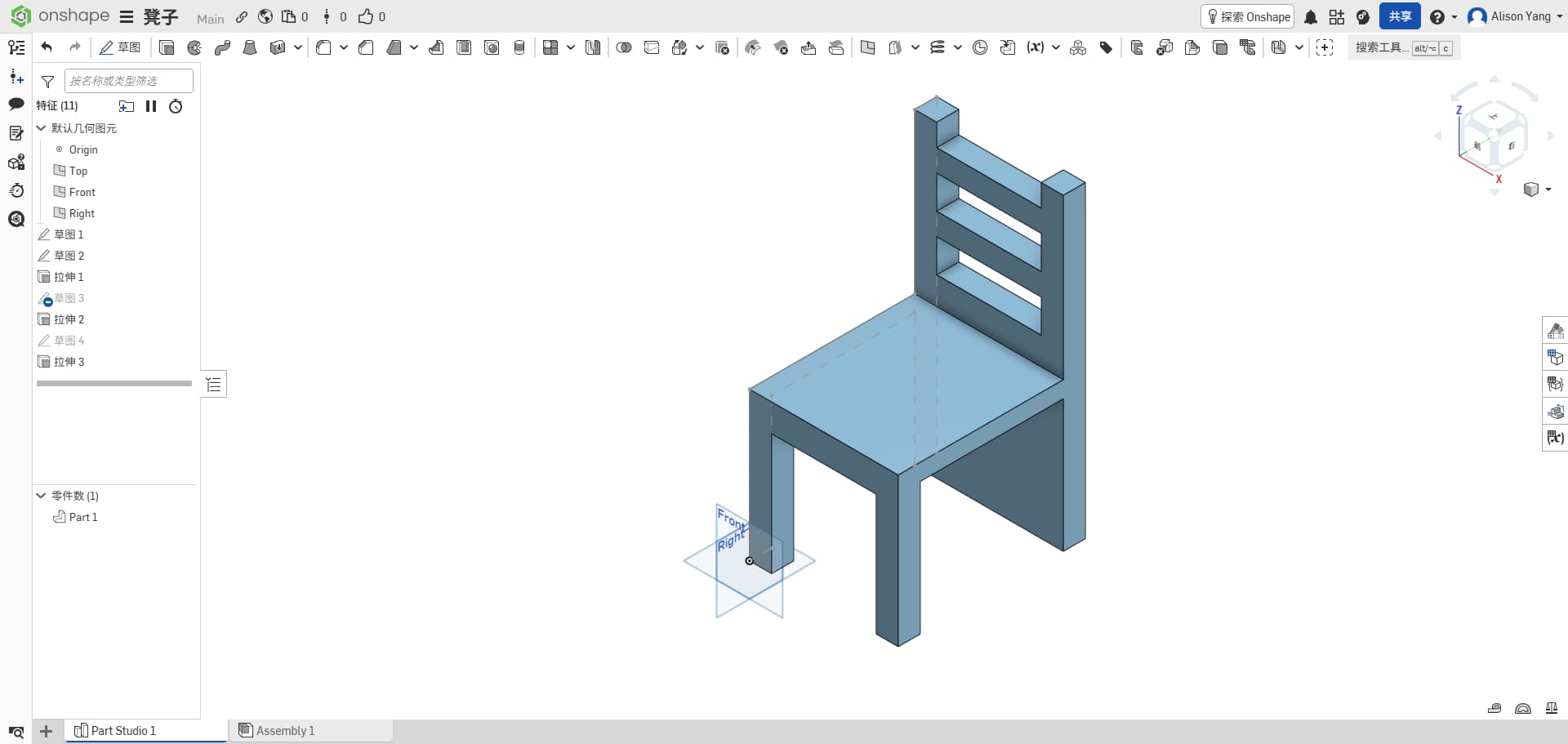
Third try
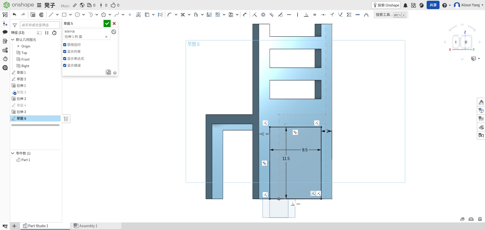
For the third version, I used what I learned from the first two and tried to make everything fit the process and the material.
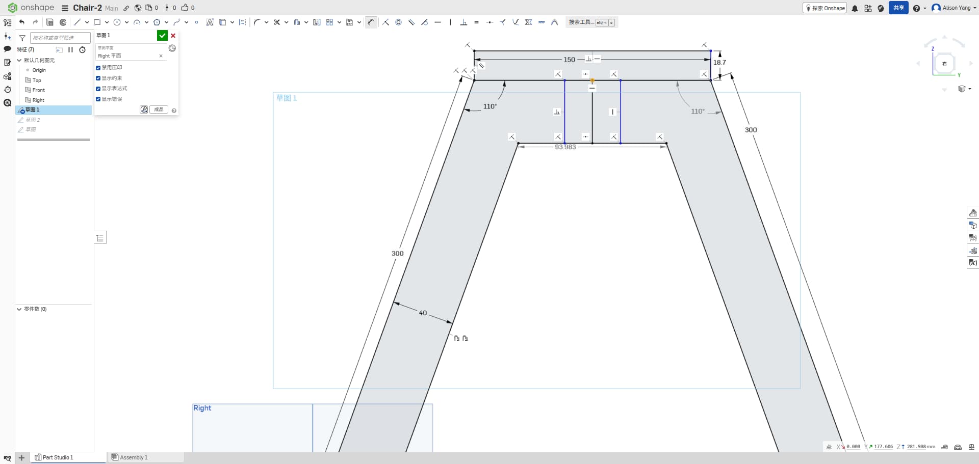
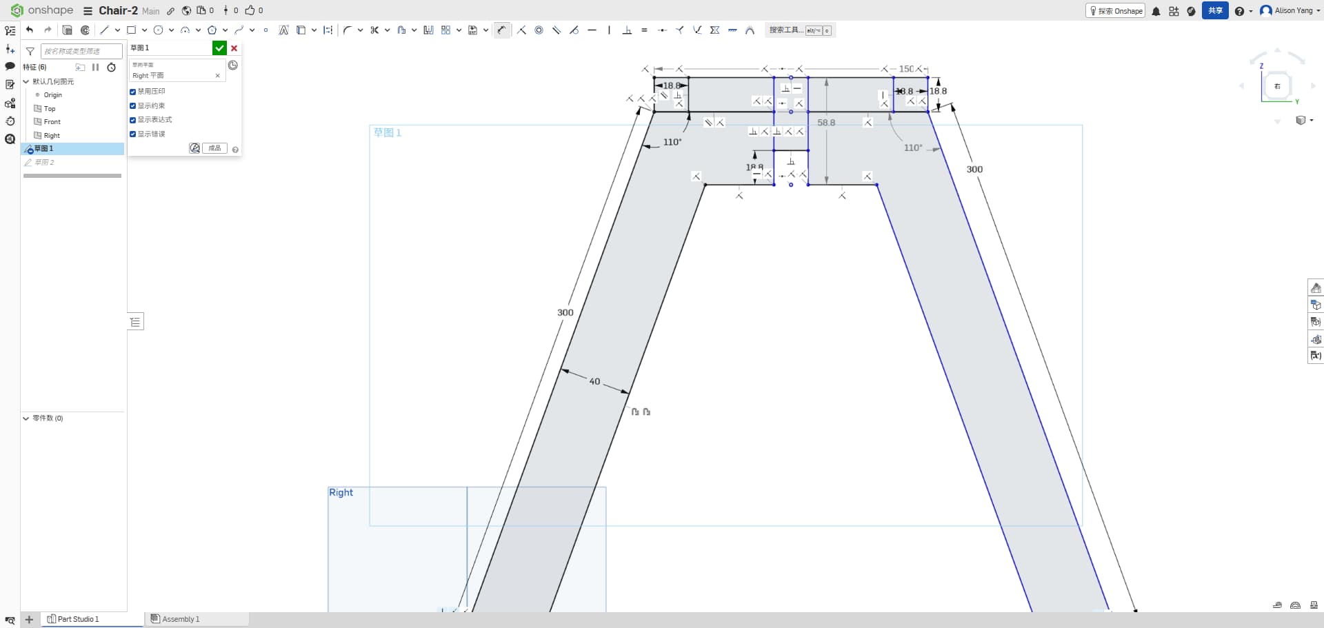
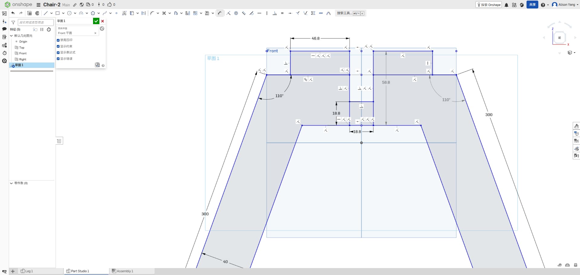
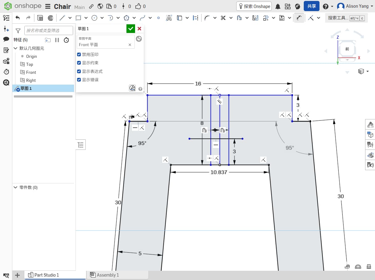
I measured our density board: it is 18.7 mm thick. Earlier designs ignored that. I also learned that because thickness is limited to 18.7 mm, any cross-shaped or interlocking joint must match that dimension in the joint design, or the parts will not fit together properly.
For this version, the legs are designed in pairs (two legs in one piece). I set the leg length to about 30 cm and the seat diameter to about 20 cm. I aimed for a snug fit, but snug still has to respect tool size, inside corners (dog-bone or T-bone if needed), and a little clearance so parts can slide together after milling.
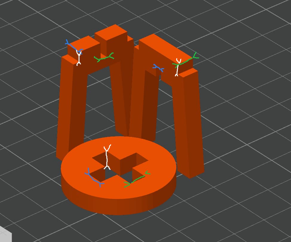
3D Printed Test
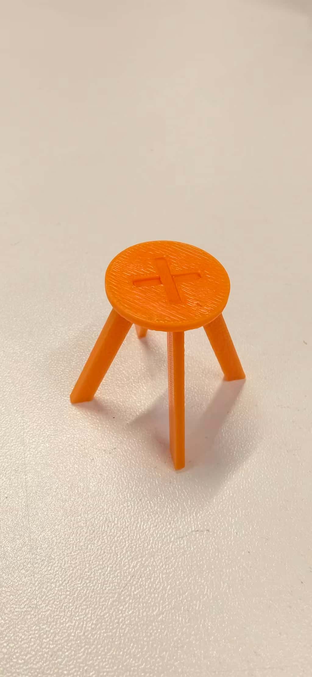
I scaled the model down to 10% (or 0.1 scale) of its original size to create a smaller version suitable for 3D printing.
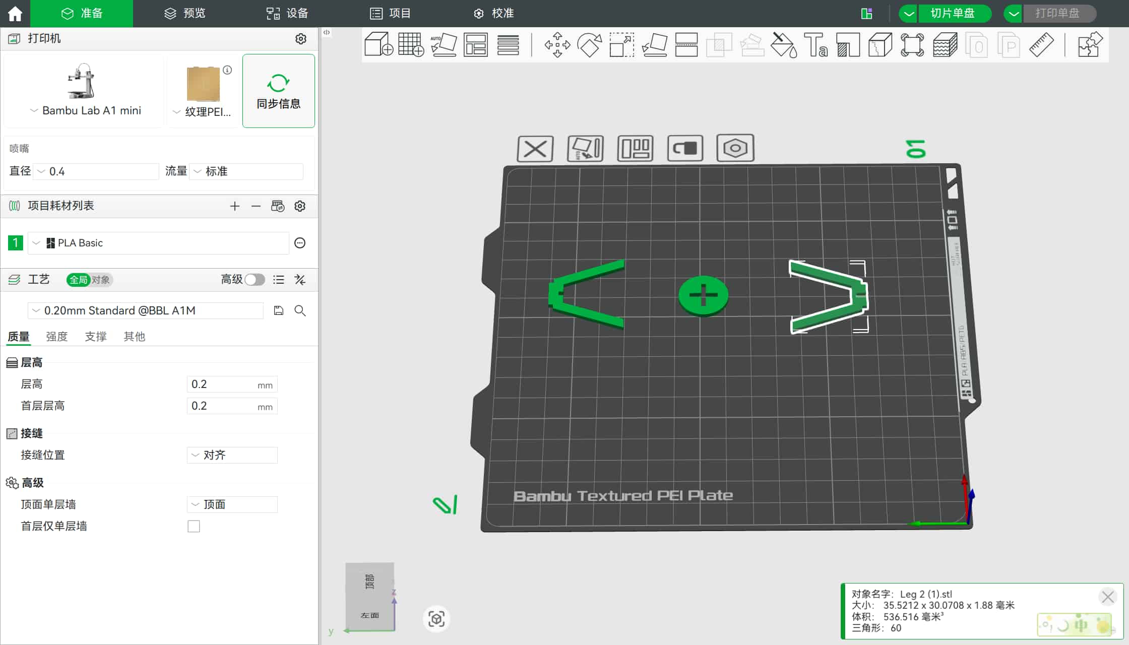
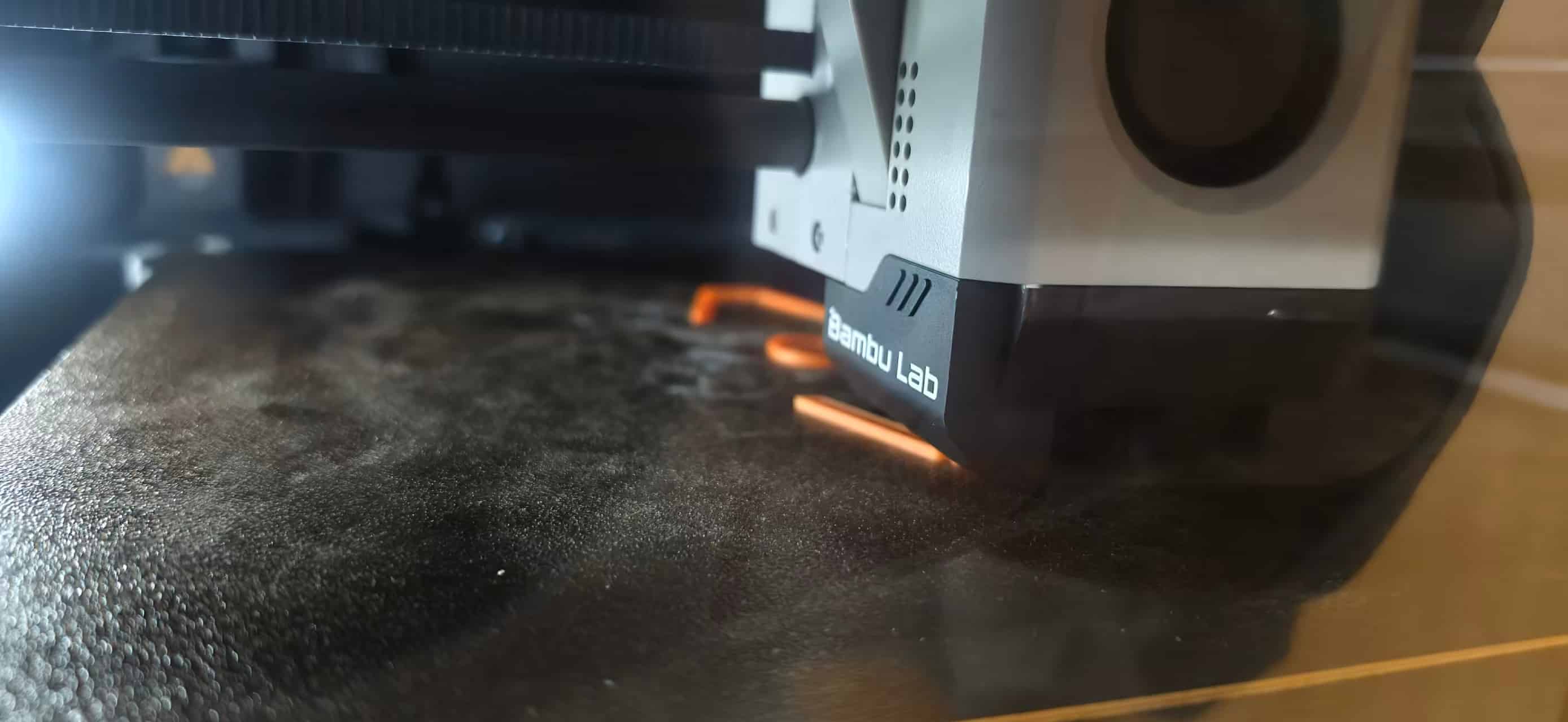
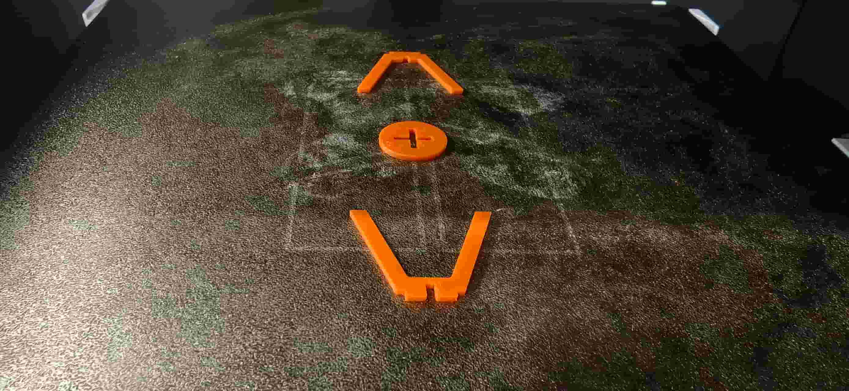
And used bamboo mini to printed, it works well. I am really happy, that it printed successfully.
MasterCAM X6
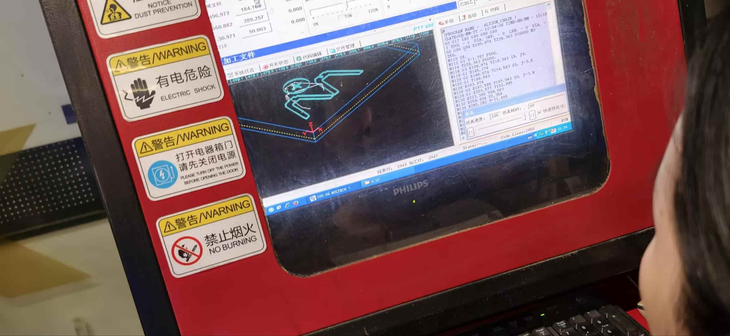
In MasterCAM (X6), we followed these steps:
1. Import design files
We imported the DXF files and defined the board / stock in the workspace so the geometry sat in the right place for machining.
2. Layout, toolpaths, and parameters
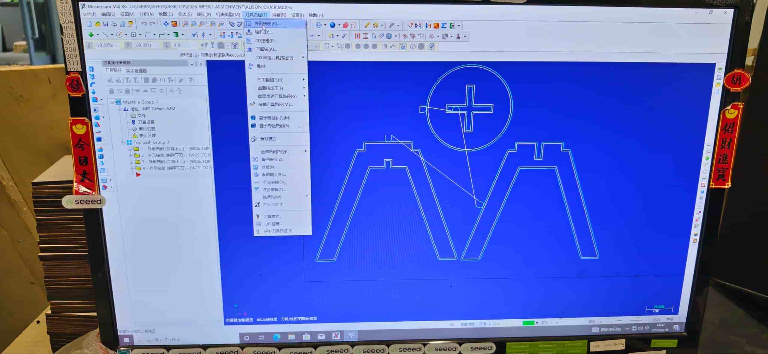
This part of the work is relatively complex; our instructor Matthew did most of the hands-on CAM while we observed and asked questions.
- Contour toolpath: Set up the contour operation for the outlines we needed to cut.
- Tool setup: Key values included 8 mm tool diameter, feed rate 5000 mm/min, spindle speed 15 000 rpm, and the usual cutting / depth settings for our material.
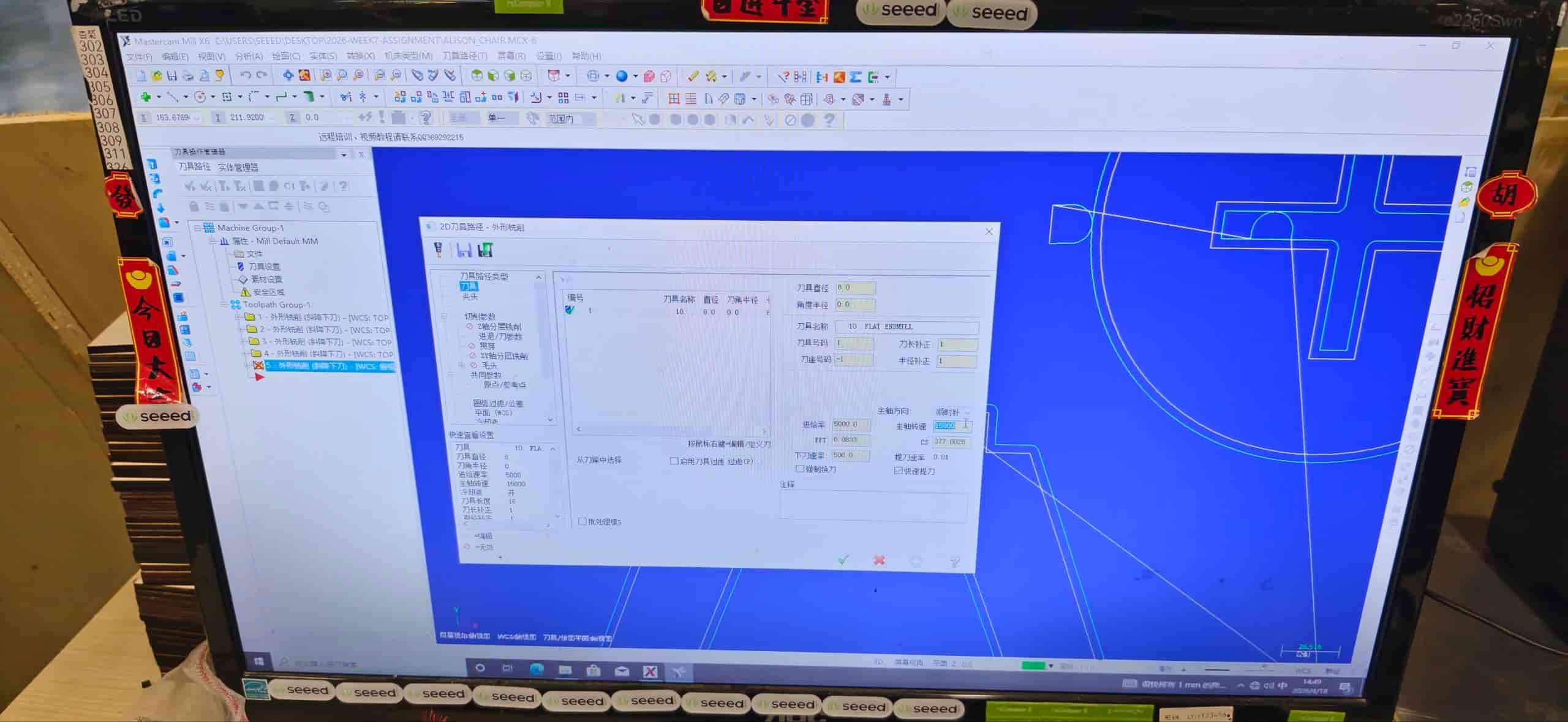
- Cutting parameters: We checked depths per pass, clearance, and compensation so the cut would match the design after the bit radius was taken into account.
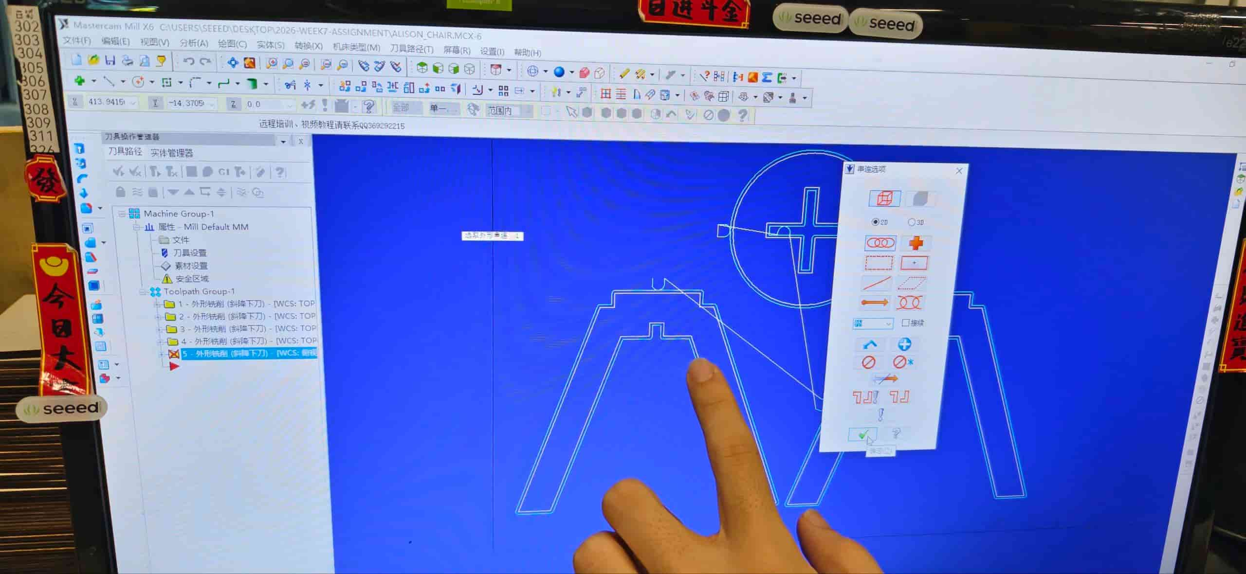
- Order of operations: Toolpaths were sequenced following the “inside to outside, small to large” : cut inner features and smaller regions first, then work outward so the sheet stays stable for as long as possible.
Inside vs. outside cutting:
Inside cutting means the tool runs on the inside of a closed shape, for pockets and holes. Outside cutting means it follows the outer boundary to separate a part from the sheet.
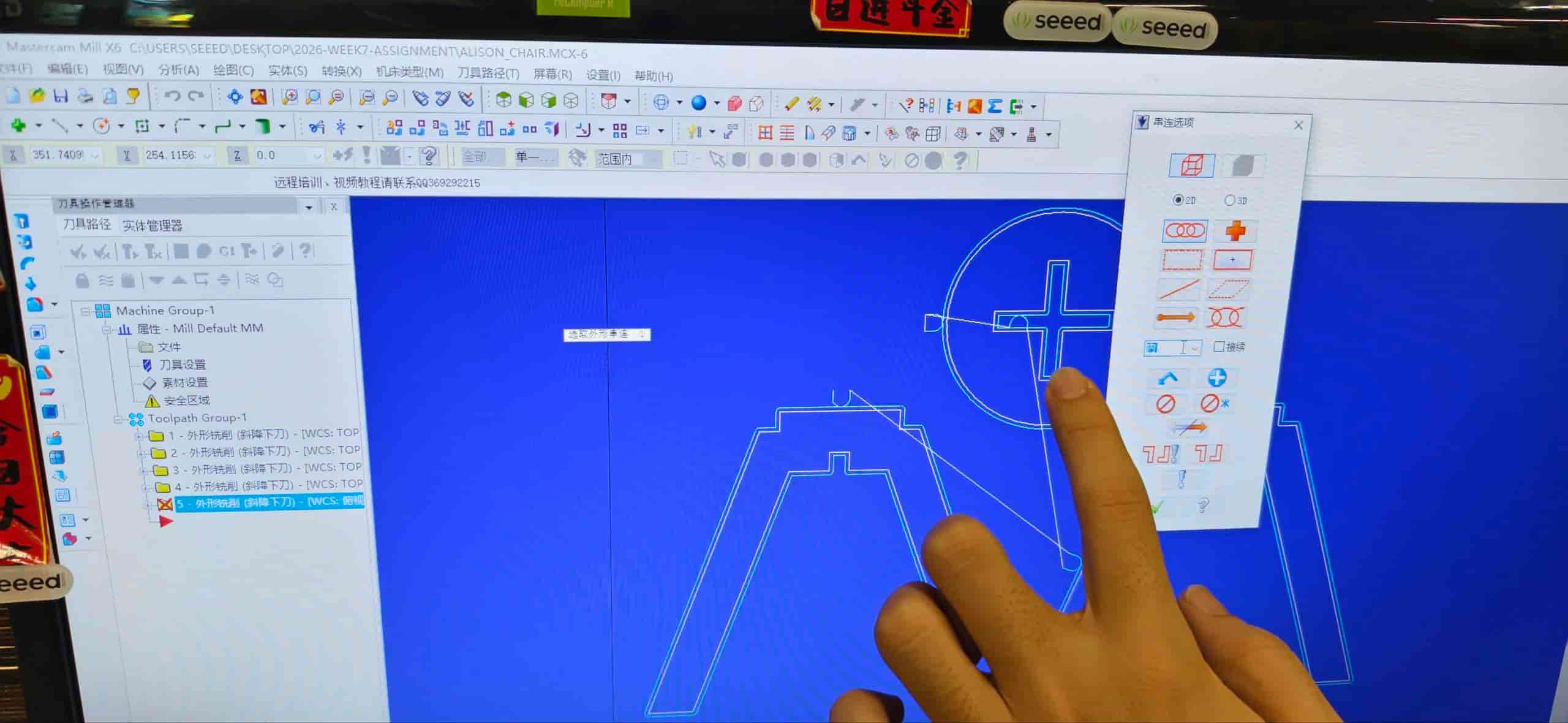
Tool radius compensation tells the control to offset the path by the cutter radius so the finished size matches the drawing; you can tweak compensation without redrawing everything.
Planning and checking the paths: We used simulation to review the job. For pockets that had to be cleared, the toolpath sits inward from the line; for outer contours that cut the part free, the compensated path sits outward from the line. The simulation also showed how the job was split into layers (multiple Z passes) instead of one deep cut.
3. Set the machining zero
After the layout and toolpaths looked correct, we set the processing zero (origin) so the machine knew where X/Y/Z start relative to the board.
4. Generate G-code
When the parameters were confirmed, we post-processed the file and generated the final G-code for the CNC.
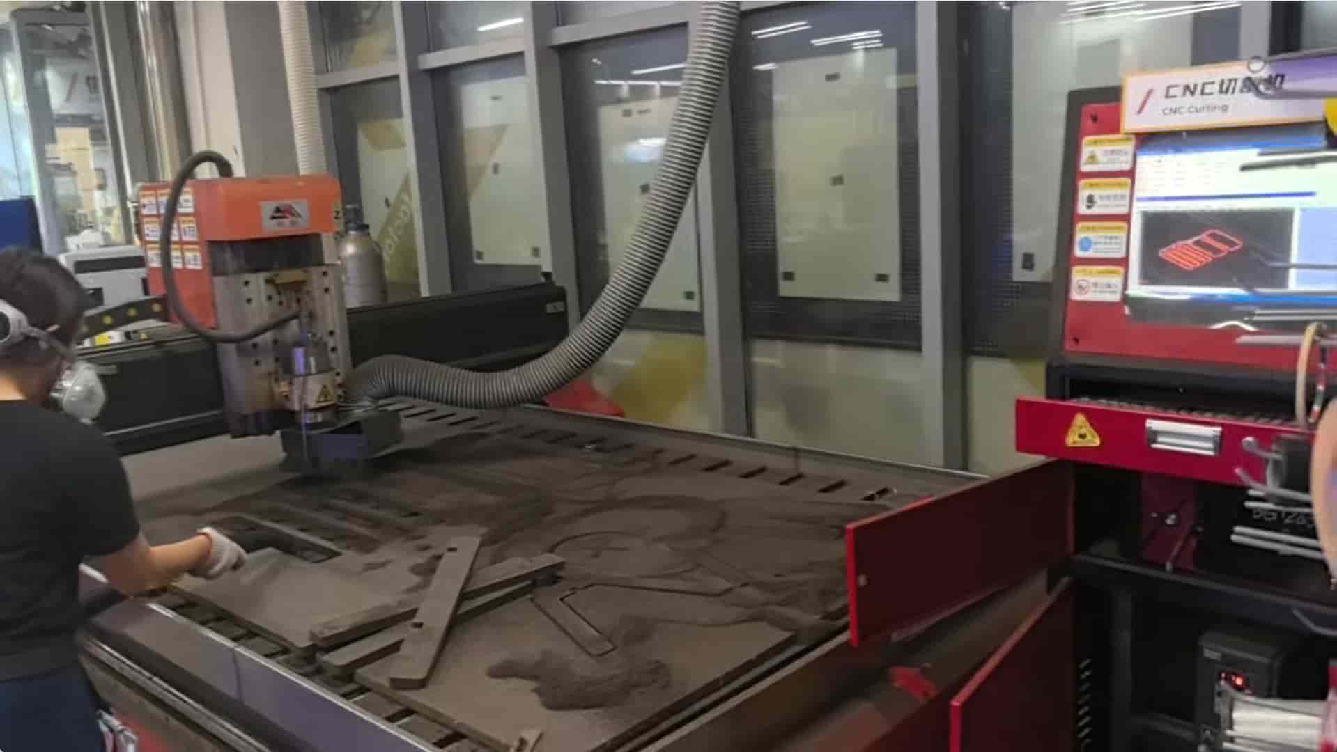
CNC cutting process
During cutting, we followed this sequence:
- Place the board on the machine table.
- Secure the material so nothing can shift during the job.
- Adjust the processing zero to match the CAM setup.
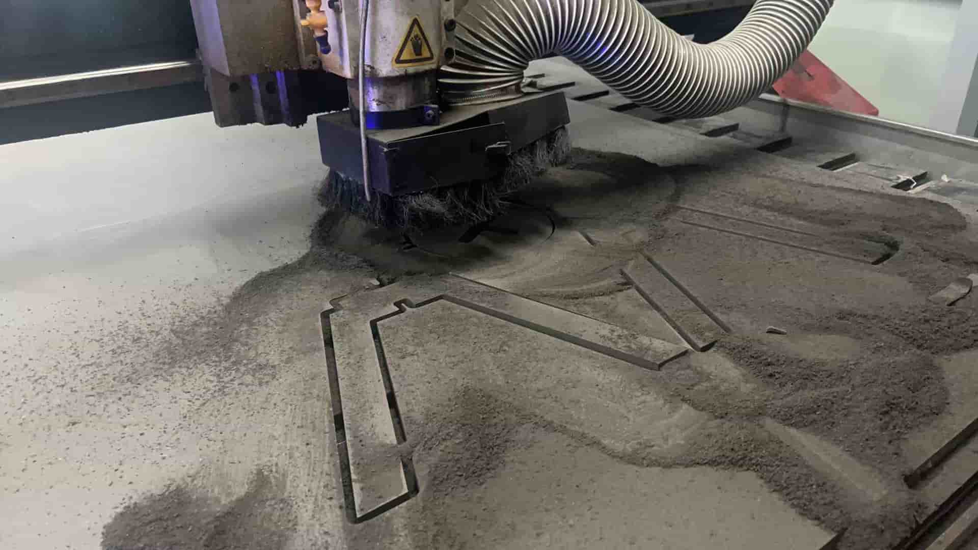
- Turn on air / dust collection (and any required extraction) so chips and dust are controlled.
- Confirm the program and settings on the controller before starting.
- Monitor the cut. If a small part breaks free from the main sheet before the outer contour is finished, pause (we used F10), wait until the spindle has fully stopped, then remove the loose piece. If you leave loose parts spinning or catching on the bit, they can damage the last passes or the tool. Only move or grab parts after a pause and when the bit is not turning.
- Clean the area when the job is done, sweep chips, check the spoilboard, and leave the machine ready for the next user.
 Thanks for Tim & Emily!
Assembling the chair
After all the pieces were cut, I assembled the small chair:
- Check the parts look for tear-out, tabs, and whether slots and corners match the drawing.
- Check the cut quality: edges should be straight enough for the joints to line up.
- Inner corners: I had not put dog-bones in the CAD for every tight inside corner, so the front joints were a little tight where the bit left a rounded inside corner. I used a wood file to ease those spots slightly until the fit felt right.
- Dry fit, then press together: I used a tongs (no rubber mallet found that time) to tap the parts together carefully (I put another board on the top to escape dents the MDF).
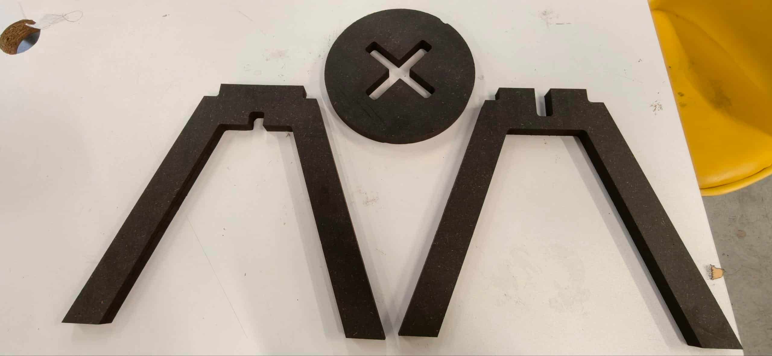
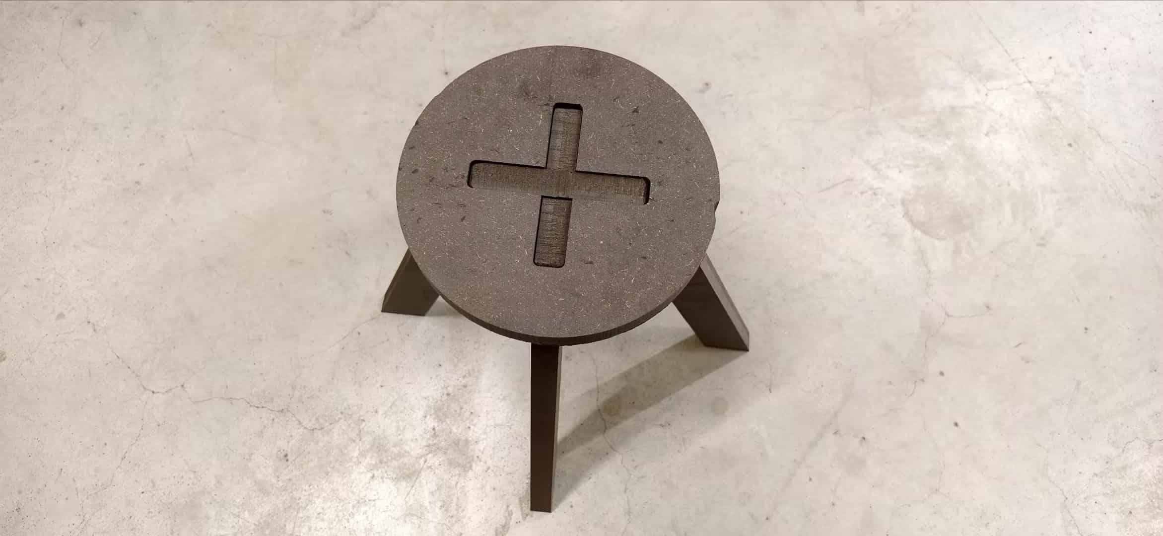
Cut chair parts
The chair is a bit small (as designed), but it sits level and feels fine for a light seat. After assembly I tested how much load it could take, and it felt surprisingly sturdy for such a compact glued-up / slotted structure.
Experience summary
- Design for the process: When you design for CNC, you have to think about inner corners, tool diameter, order of cuts, and sheet hold-down. Avoid “impossible” inside corners or features the bit cannot reach without a second setup unless you plan for it.
- Tool quality matters: A good, sharp bit and sensible feeds/speeds reduce tear-out and broken tools. Soft or dull bits break or burn more easily and can stop the whole job.
- Parametric design helps: If thickness or slot width changes, a parametric model lets you update dimensions without redrawing every sketch from scratch, very useful when the real board measures 18.7 mm instead of “18 mm on the label.”
- Slots for inserted panels: For small square holes meant to receive a tab of the same board thickness, remember clearance: in our notes we aimed for about +3 mm total width (extra space on both sides of the nominal size) so the tab can slide in without jamming — tune this using your measured thickness and a test cut if possible.
- Safety first: Masks, hearing protection, knowing pause / emergency stop, and never reaching toward a moving spindle. The machine is fast and the bit is unforgiving.