Week 16 — System Integration
This week was the moment when all the separate pieces finally started to become one complete project. I connected the three main parts together: the visitor touch module, the local Node.js hub, and the 7.3 inch color ePaper display module. They could now communicate through WiFi and work together as a whole system.
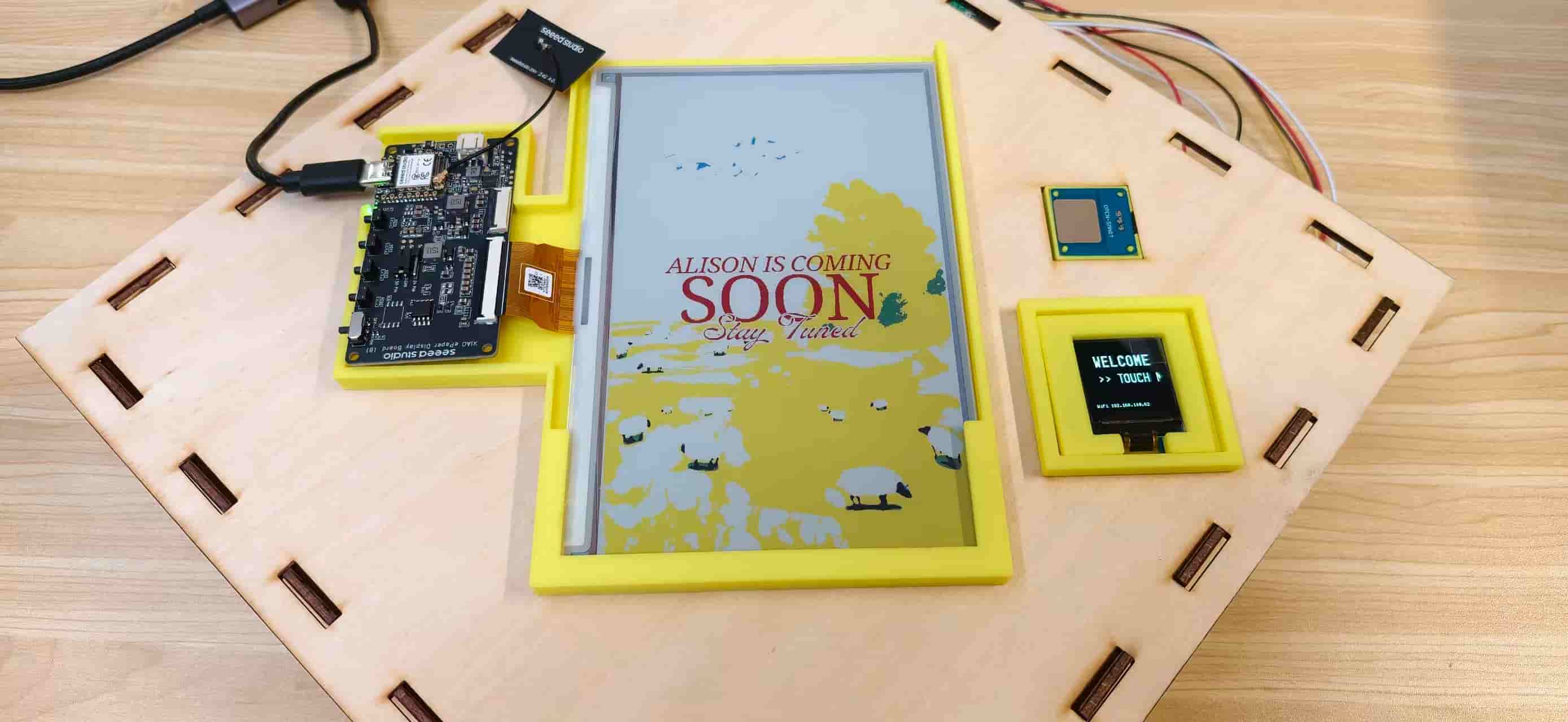
Integrated bench test: S3 + ePaper on the left, C3 OLED and touch sensor on the right, all mounted on the laser-cut top panel.
At the beginning, I thought the most challenging part would be the electronics and programming. I spent a lot of time making the boards communicate, controlling the display, and building the interaction logic.
But when I started putting everything together, I realized that the physical structure became the biggest challenge. I designed many parts while imagining them sitting on a table, but the final project was actually going to be installed vertically on a wall or placed near a door. This changed many things, how the components should be arranged, how they should be supported, and how the whole system could stay stable and easy to use.
So I started to rethink the structure and designed holders for the ePaper display, OLED screen, and touch sensor. Instead of only focusing on whether each component could work, I needed to think about how they could become one object that people could interact with naturally.
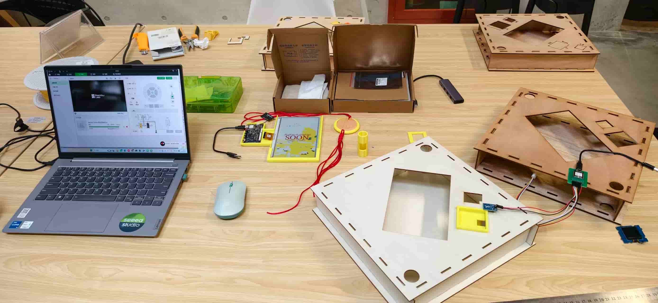
The real integration table, four laser-cut box variants, printed holders, boards, and the laptop all competing for space.
During this integration process, I realized that building a complete system is not just about connecting wires or making code run. It is about making different parts understand each other, the mechanical structure, the electronics, the firmware, and the user experience. A simple touch on the visitor module should finally create a smooth chain of responses: the OLED greeting, the web dashboard update, and the ePaper poster change.
What I Was Integrating
Smart Fu - Digital Door Guardian is a calm-technology visitor notification object inspired by traditional Chinese Fu (福) door decorations. Most of the time it shows a decorative Fu poster on a large ePaper screen.
When someone touches the small sensor near the entrance, three things happen in sequence:
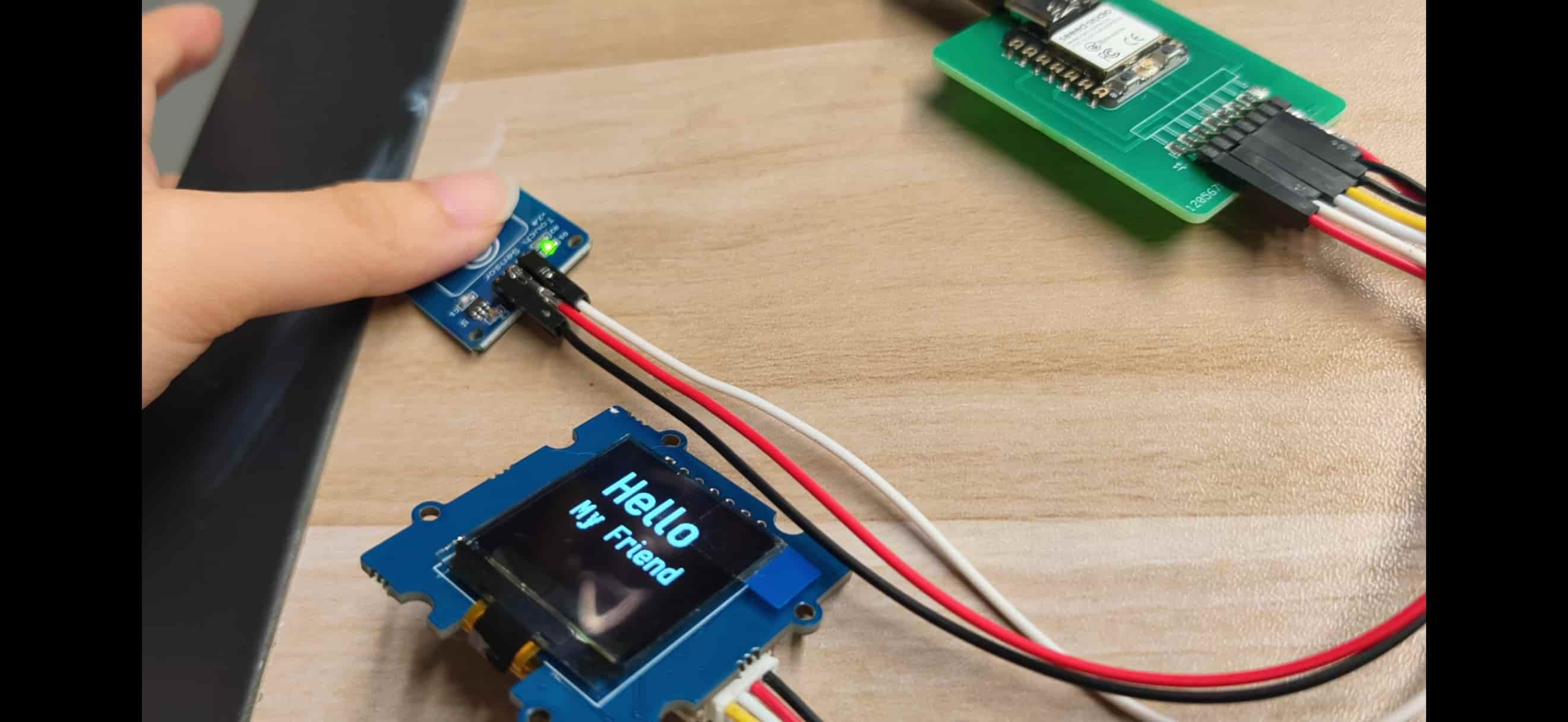
- The XIAO ESP32-C3 OLED greets the visitor with
Hello / My Friend. - The Node.js server records a touch event and updates shared state.
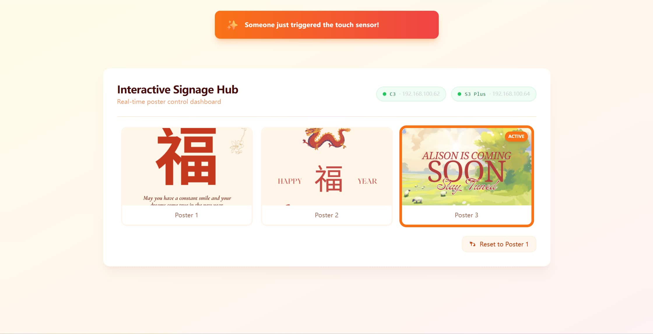
- The web dashboard shows an orange toast alert, and the XIAO ESP32-S3 Plus switches the 7.3 inch Spectra 6 ePaper to the visitor poster within about five seconds.
The same server also supports manual poster control from a browser and a reset action that returns the whole system to poster 1.
Why This Week Felt Different
Before this week, each part of my project had already been tested separately. I had worked on input devices, output devices, networking, interface programming, CAD design, laser cutting, and 3D printing in different stages. But making them work together as one complete system was a completely different challenge.
Integration meant that every small detail suddenly became important. A problem was not always coming from the code. Sometimes it was a physical issue, like a holder being 0.5 mm too shallow, a cable having no space to move, or a display not fitting perfectly into the frame. Other times it was a software problem, such as the wrong WiFi network, repeated touch events, or the ePaper refreshing at the wrong timing.
This week was less about learning one new technique, but more about making all the skills I learned before communicate with each other.
| Layer | What I needed to check |
|---|---|
| Mechanical | Whether the laser-cut frame and 3D-printed holders fit together, whether the display was stable, and whether the components could be maintained after installation |
| Electrical | Whether the two ESP32 boards, OLED, touch sensor, and ePaper driver could work together without connection problems |
| Firmware | Whether the devices could start correctly, send the right signals, and avoid unnecessary updates |
| Network | Whether the C3, S3, and Node.js server could share the same information through WiFi |
| UI/UX | Whether the visitor could get immediate feedback while the indoor display updated smoothly |
How the System Fits Together
The final system became a small local network with one central hub and two interactive devices.
The laptop works as the local hub, running the Node.js server and managing the communication between different parts. The ESP32-C3 works as the visitor interaction module, detecting touch input and giving immediate feedback through the OLED display. The ESP32-S3 controls the 7.3 inch color ePaper display and updates the poster content based on the visitor interaction.
The whole system communicates through the same local WiFi network. thanks for Opencode, the system works pretty well:
┌─────────────────────┐
│   PC (192.168.100.18)   │
│   node server.js      │  ← backend + web dashboard + REST API
│   localhost:3000      │
└──────────┬──────────┘
           │ WiFi
     ┌─────┴─────┐
     │           │
┌────┴────┐  ┌───┴──────────────┐
│ XIAO C3 │  │ XIAO S3 Plus     │
│ OLED    │  │ + EE04 driver    │
│ Touch   │  │ + 7.3" ePaper    │
└─────────┘  └──────────────────┘
Hub — PC running Node.js
The laptop acts as the brain of the system. It stores the current poster status, records interaction history, and provides the interface for monitoring.
| Item | Detail |
|---|---|
| Host | Development laptop at 192.168.100.18 |
| Process | node server.js in the interface/ folder |
| Port | 3000 |
| Role | Single source of truth for currentPoster, event history, and device online status |
The server hosts the dashboard, poster images, and REST APIs. Instead of making the ESP32 boards discover the server automatically, I used a fixed local IP address. This made the connection more stable during testing.
Edge device A — XIAO ESP32-C3 (visitor interaction)
The ESP32-C3 is the part that visitors interact with directly. Its main job is simple: detect a touch, show an immediate response on the OLED screen, and send one reliable event to the server.
| Item | Detail |
|---|---|
| Board | Custom Fab Academy ESP32-C3 PCB |
| Display | 128 × 128 Grove OLED (SH1107, I2C) |
| Input | Grove touch sensor on D2, INPUT_PULLUP |
| Firmware | c3_touch_sender/c3_touch_sender.ino |
| Libraries | U8g2 for OLED text rendering |
One thing I learned during integration was that the physical design was just as important as the electronics. The OLED and touch sensor were originally tested on the table, but the final project needed to work vertically near a door.
Because of this, I redesigned the holders several times to make sure the components could be mounted firmly while still being easy to remove for debugging.
Edge device B — XIAO ESP32-S3 Plus (ambient display)
The ESP32-S3 controls the large ePaper display, which acts as the ambient information board.
| Item | Detail |
|---|---|
| Board | Seeed XIAO ESP32-S3 Plus |
| Driver | EE04 ePaper driver board |
| Panel | 7.3 inch Spectra 6 color ePaper (800 × 480) |
| Firmware | EE04_S3_Poster/EE04_S3_Poster.ino |
| Config | driver.h — BOARD_SCREEN_COMBO 509 + USE_XIAO_EPAPER_DISPLAY_BOARD_EE04 |
| Libraries | Seeed_Arduino_LCD / Seeed ePaper stack |
The ePaper module was placed inside the laser-cut wooden frame. Although the CAD design looked correct, the real assembly required several iterations.
I redesigned the ePaper holder six times in PLA. The most important adjustments were the display depth, the EE04 board position, and the cable direction. A difference of only 0.5 mm could change how the display pressed against the frame.
This was a good reminder that digital design and physical fabrication are always connected. A model that looks perfect on the computer still needs real-world testing.
Network constraint — 2.4 GHz only
One small but memorable problem happened with the WiFi connection.
Both ESP32 boards need to connect to the X.factory2.4G network because ESP32 only supports 2.4 GHz WiFi. At first, I used the normal X.factory network and spent a long time checking my code because the boards looked like they were not working.
The firmware compiled successfully and the Serial Monitor looked normal, but the connection never completed. Later I realized the problem was not the code — it was simply the WiFi band.
This was one of those integration problems that is easy to overlook: sometimes the hardest bugs are not inside the program, but somewhere around the system.
What the System Actually Does
The system behavior is defined by a small set of triggers and observable outcomes. These were the acceptance tests I used during integration.
| Trigger | System response |
|---|---|
| Touch C3 sensor | ① C3 OLED shows Hello / My Friend for 2 s → ② POST status=coming → ③ Web dashboard orange toast + S3 ePaper switches to poster 3 within ~5 s |
| Click poster on web | POST poster=1/2/3 → S3 ePaper switches to the selected poster within ~5 s |
| Reset button on web | POST /api/reset → currentPoster = 1; all clients return to poster 1 |
Poster states
Three bitmap posters are compiled into images.h and flashed to the S3:
| ID | Role | Content |
|---|---|---|
| 1 | Default / idle | Calm Fu blessing artwork |
| 2 | Alternate display | Festive Fu variant |
| 3 | Visitor alert | Triggered by touch or manual selection |


Shared server state
The Node.js process maintains one JSON state object:
currentPoster      → 1 | 2 | 3
lastEvent          → "touch" | "web" | "reset" | null
lastEventTime      → ISO timestamp
devices.c3         → { ip, lastSeen, online }
devices.s3         → { ip, lastSeen, online }
Device liveness: A device is marked online if its lastSeen timestamp is within 15 seconds. The C3 updates lastSeen on touch POST; the S3 updates it on each GET /api/status?device=s3 poll.
UI/UX integration principles
Integration is not complete until the experience is coherent across all three surfaces:
| Surface | UX goal | Engineering constraint |
|---|---|---|
| C3 OLED (128 px) | Visitor sees instant welcome | Font size and line breaks must fit; use logisoso22 + logisoso18 |
| ePaper (800 × 480) | Indoor household sees calm poster change | Refresh takes seconds; avoid unnecessary updates to protect panel life |
| Web dashboard | Resident monitors state without noise | Toast only on new touch events; device pills show IP + online dot |
The 5-second poll interval on the S3 is a deliberate trade-off: fast enough that a touch feels responsive indoors, slow enough to limit ePaper wear and reduce SPI/WiFi contention on the S3.
flowchart LR
    A[Visitor touches D2] --> B[C3 OLED greeting]
    B --> C[POST status=coming]
    C --> D[Node.js state update]
    D --> E[Dashboard toast]
    D --> F[currentPoster = 3]
    F --> G[S3 polls GET /api/status]
    G --> H[ePaper refresh poster 3]
My Integration Journey: Seven Stages
I did not build the final system in one attempt. Instead, I gradually connected each part together and tested them step by step. This process helped me understand where problems came from because every new layer was built on top of the previous one.
Looking back, this was probably the safest way to approach the integration. When something stopped working, I could narrow down the problem instead of debugging the whole system at once.
Stage 1: Making the ePaper Display Work
The first step was to make sure the S3, EE04 driver, and 7.3 inch Spectra 6 ePaper could communicate successfully.
I started by installing the Seeed_Arduino_LCD library and configuring the driver.h file with:
BOARD_SCREEN_COMBO 509USE_XIAO_EPAPER_DISPLAY_BOARD_EE04
The first goal was simple: display a basic image and text on the screen. After several tests, I successfully displayed my first full-color poster.
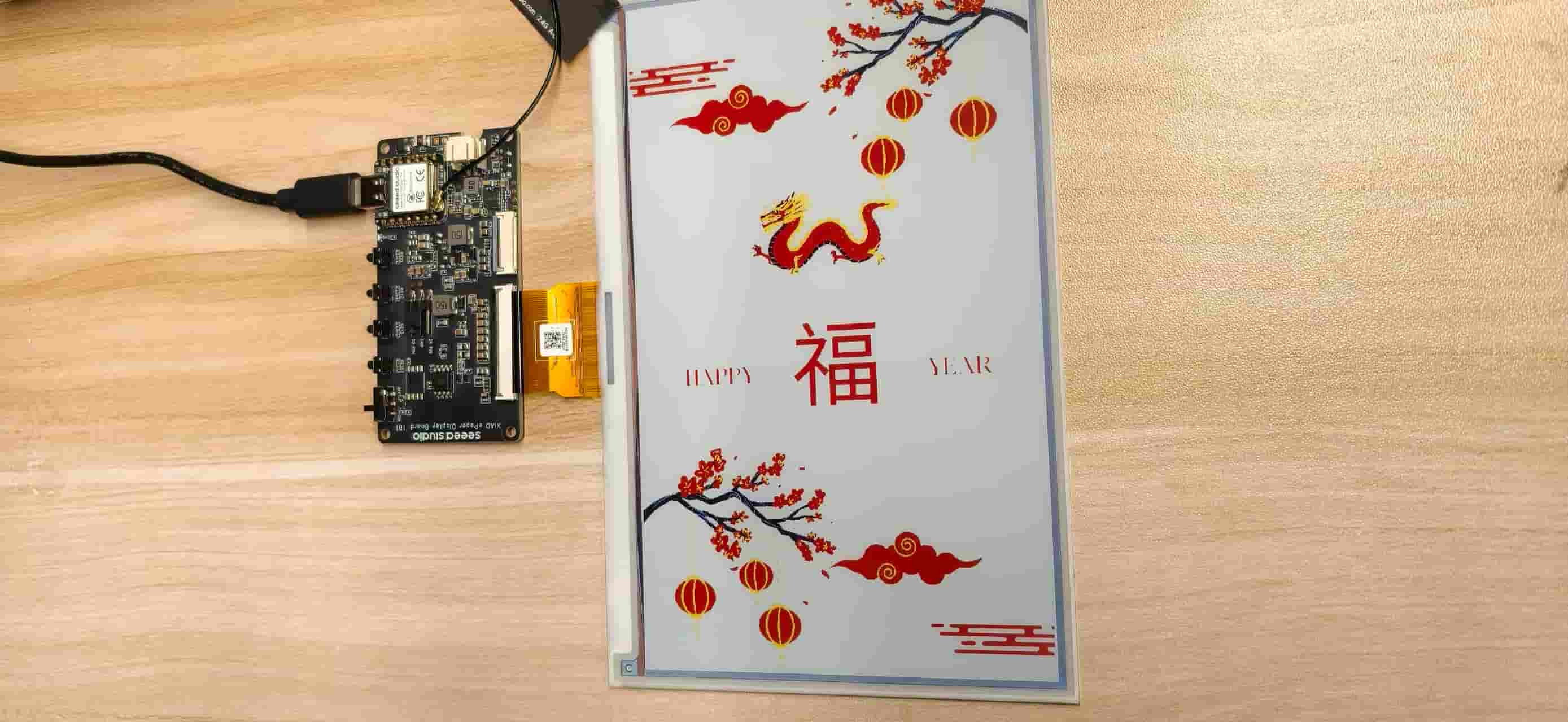
First successful full-color poster on the 7.3 inch panel.
One problem I encountered was a library conflict. I originally had TFT_eSPI installed, which caused conflicts with Seeed_GFX symbols and prevented the project from compiling.
After removing the unused library and keeping only the Seeed ePaper toolchain, everything worked again.
This reminded me that hardware integration is often not only about writing code. The environment, libraries, and dependencies can also become part of the challenge.
This was a small but important lesson. For embedded displays, the image pipeline is as important as the firmware itself. A perfect program cannot fix an incorrect asset format.
Stage 3: Building the Web Console
Before connecting the touch sensor, I wanted to control the posters manually.
I built a simple Node.js Express server with:
GET /api/statusPOST /api/statusPOST /api/reset
The dashboard displayed poster thumbnails, and I could switch the ePaper content directly from the browser.
This step was very useful because it separated the problems. If the poster failed to update, I could focus on the S3 and ePaper side instead of wondering whether the touch interaction caused the problem.
Stage 4: Connecting the S3 to the Network
After the manual control worked, I connected the S3 to the local server.
The workflow became:
- S3 connects to WiFi
X.factory2.4G - S3 checks the server status every 5 seconds
- When currentPoster changes, the ePaper updates
I also added a state check so the display only refreshes when the poster actually changes. This helps reduce unnecessary ePaper refreshes and protects the display lifetime.
A small but memorable problem happened here. At first, I used the wrong WiFi network.
The code was correct, the board was running, and the Serial Monitor looked normal, but the connection never succeeded. After checking carefully, I realized the ESP32 could only connect to the 2.4 GHz network.
Switching to X.factory2.4G immediately solved the problem.
Stage 5: Solving the ePaper Sleep/Wake Problem
This was the most difficult part of the integration.
The first poster could display correctly, but when I tried to switch to another poster, the S3 sometimes stopped responding.
At first, I thought the problem was related to WiFi or memory. After many tests, I found that the actual issue came from the ePaper controller sleep sequence inside the library.
After refreshing, the controller entered deep sleep and could not wake up correctly for the next update.
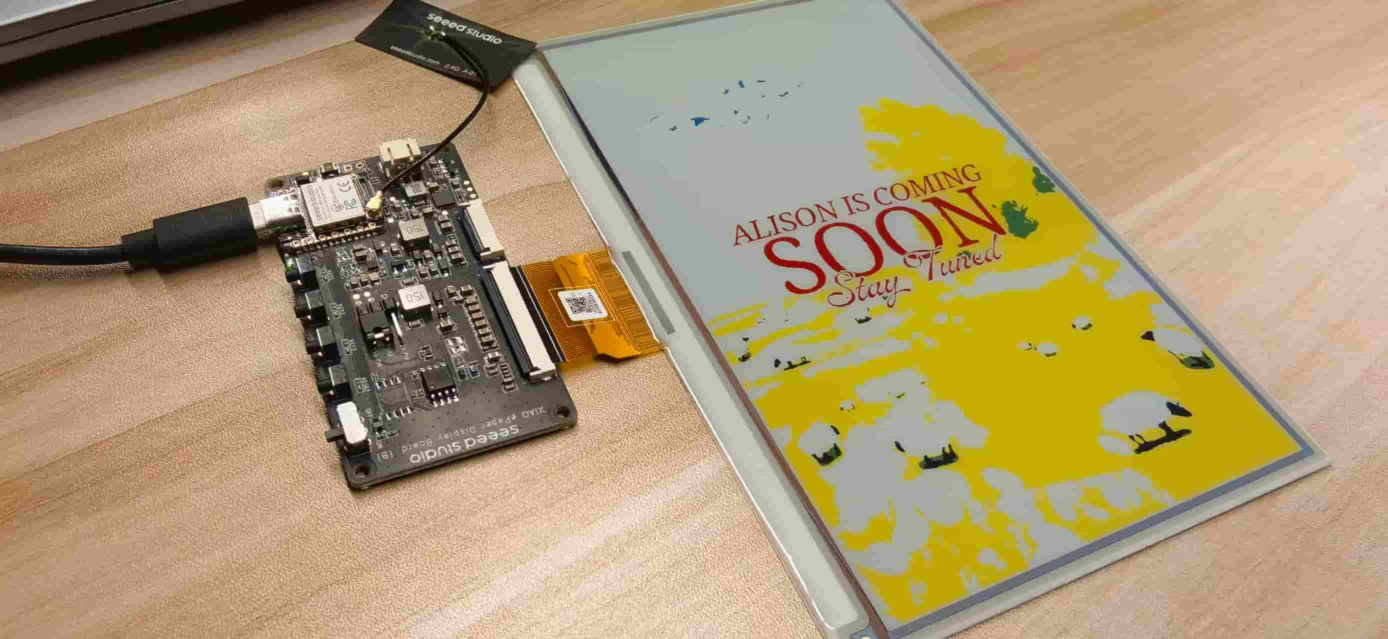
Poster 3 "Alison is coming soon." This is the visitor-alert screen that only worked reliably after I fixed the sleep/wake issue.
Instead of using the default update() process, I changed to a manual refresh flow:
0x04  Power on (PON)
0x10  Push image data with manual 6-color nibble remap
0x12  Refresh display
(no deep sleep)
I also added several small improvements:
-Disconnect WiFi before sending SPI data -Use a custom pushDisplay() function -Reconnect WiFi after refreshing
This was probably the biggest turning point of the project. I spent almost two days debugging this issue, but once I understood the reason, the solution became surprisingly simple: keep the controller awake.
Stage 6: Improving the Dashboard Experience
Once the hardware communication was stable, I focused on making the interface easier to understand during demonstrations.
I rebuilt the dashboard using Tailwind CSS and added:
clearer device status indicators poster cards selected poster highlight automatic notification messages
The finished dashboard with both devices connected.
One small bug appeared during testing. The notification message kept appearing again and again because the browser received the same touch event during every polling cycle.
I solved this by storing the previous event state and only showing the notification when a new touch happened.
This was also where I started thinking more about the relationship between the physical object and the digital interface. The orange-red style of the dashboard follows the visual language of the Fu posters, making the interface feel like part of the same project instead of a separate control panel.
Stage 7: Refining the Visitor Interaction
The final step was improving the small OLED interaction on the ESP32-C3.
Because the screen is only 128 × 128 pixels, every element needed to be carefully arranged.
| Mode | OLED content | Font |
|---|---|---|
| Idle | Centered WELCOME + >> TOUCH ME; bottom line shows WiFi <IP> | logisoso22, logisoso18, 5x7 |
| Touch | Centered Hello + My Friend for 2 s | logisoso32, logisoso18 |
I also added input protection:
Debounce: 1.5 seconds to avoid accidental repeated triggers Cooldown: 3 seconds to prevent duplicate events from one touch
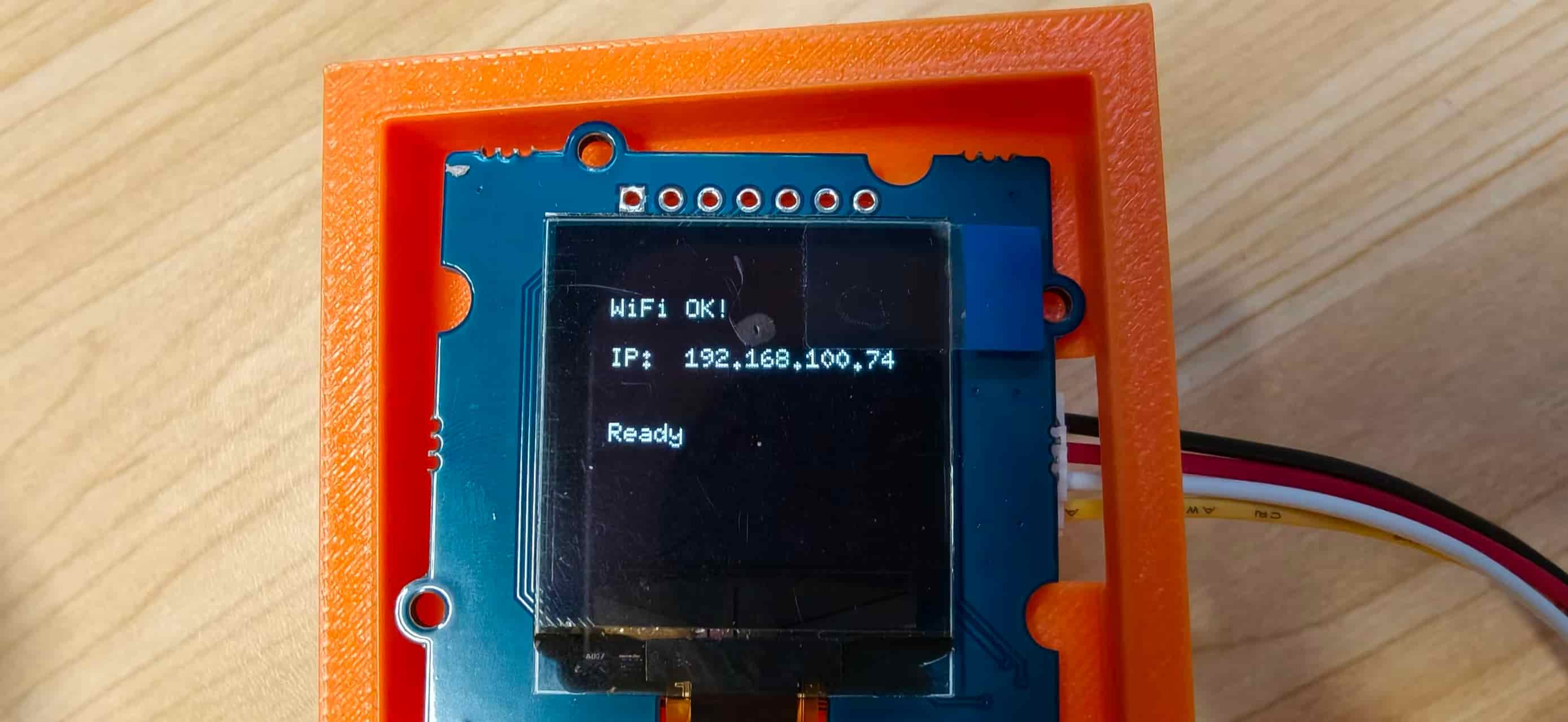
WiFi connected, the C3 OLED in its orange holder showing WiFi OK! and the assigned IP.
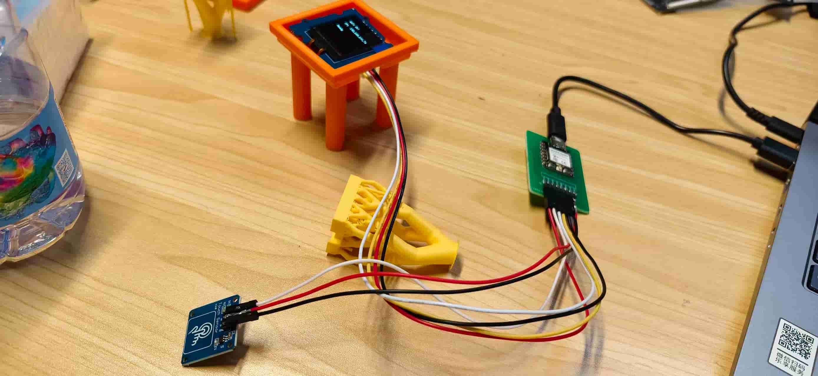
Full C3 bench setup: custom board, OLED in printed holder, touch sensor, and the yellow lattice structure I was testing as an alternate mount.
Full C3 testing setup with custom PCB, OLED, touch sensor, and printed holder.
After these seven stages, the different parts finally became one connected system. The biggest lesson from this week was that integration is not just about making every component work individually. It is about creating a smooth relationship between hardware, software, and the person using it.
Building the Physical Object
Software integration was only half the story. The Fu object also had to hold everything securely, look intentional from the front, and still open for debugging. Since traditional Fu decorations are usually square, I decided to design a square box — 30 × 30 cm footprint, about 8 cm tall, cut from 3 mm plywood — and laser-cut four variants to see which layout fit the electronics best.
Laser-cutting four boxes
I started in CAD with a square frame and a central window for the ePaper (roughly 18 × 12 cm visible area). Then I cut four versions on the laser and compared them on the bench.
Early versions ignored kerf and assembly direction. Parts looked identical after cutting and were easy to assemble backwards. I learned to mark orientation on the plywood with pencil before taking anything apart.
Then consider design the back board, plan to printed a box and showcase the cloud pattern
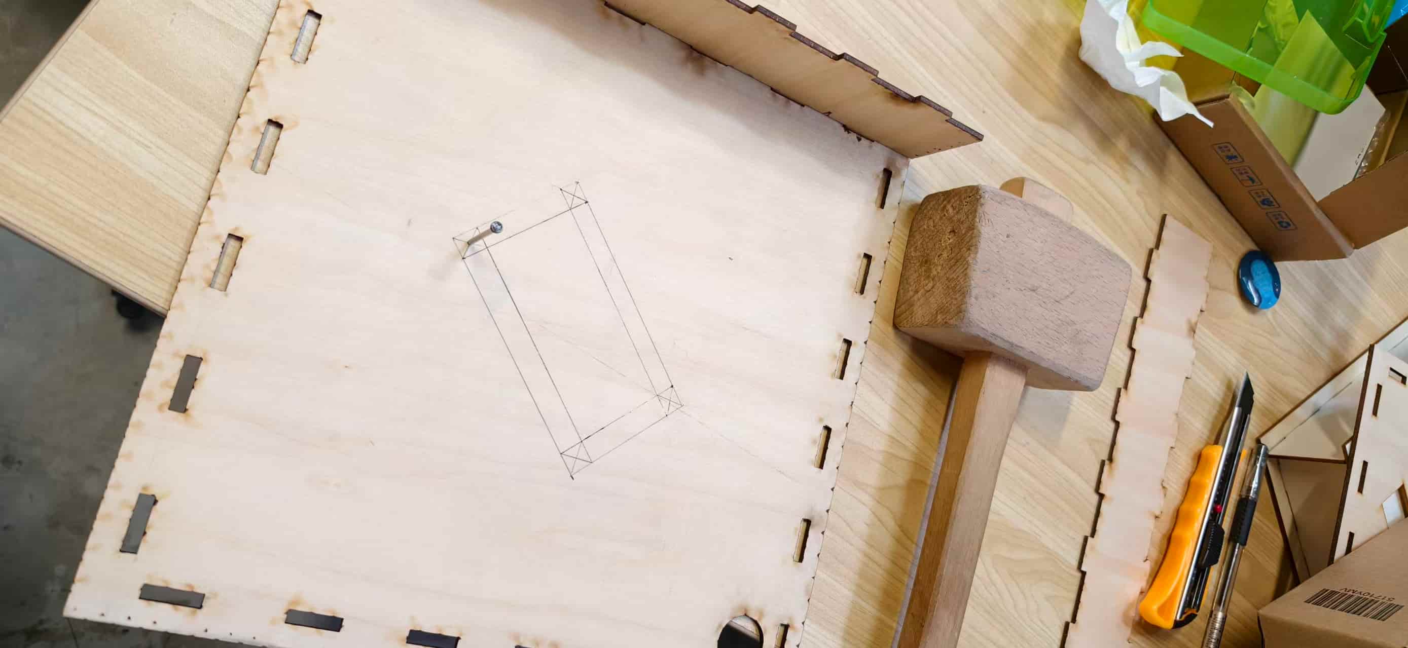
Once I had a front panel I liked, I still needed openings for the OLED and touch sensor near the ePaper window. I measured the Grove modules on the actual board, drew the sizes directly on the wood (about 4 cm × 4.5 cm for the OLED area and 2.5 cm for the touch zone), and cut a second iteration.
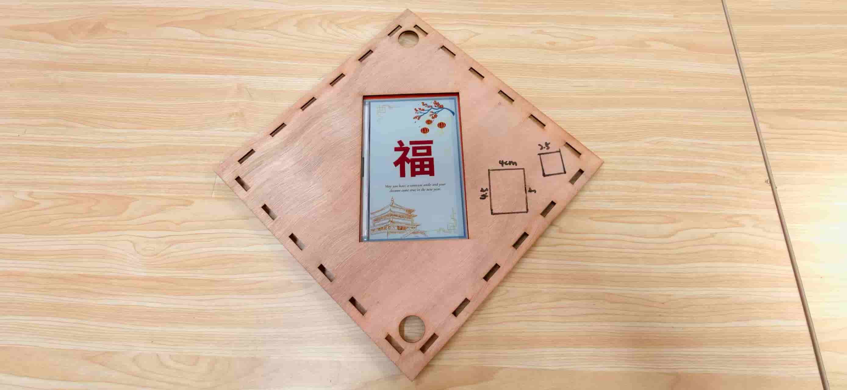
Planning the OLED and touch cutouts by hand — sometimes CAD needs a reality check on the bench.
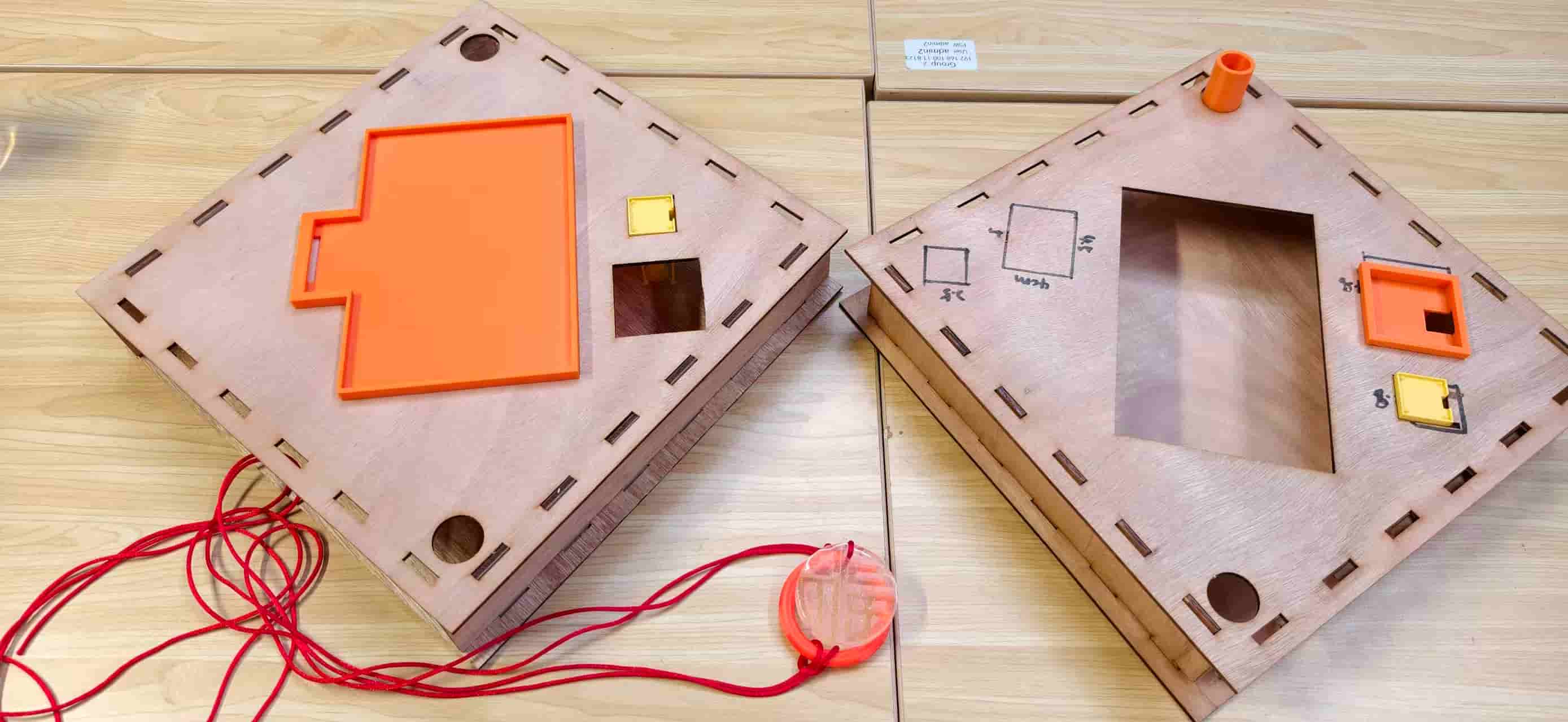
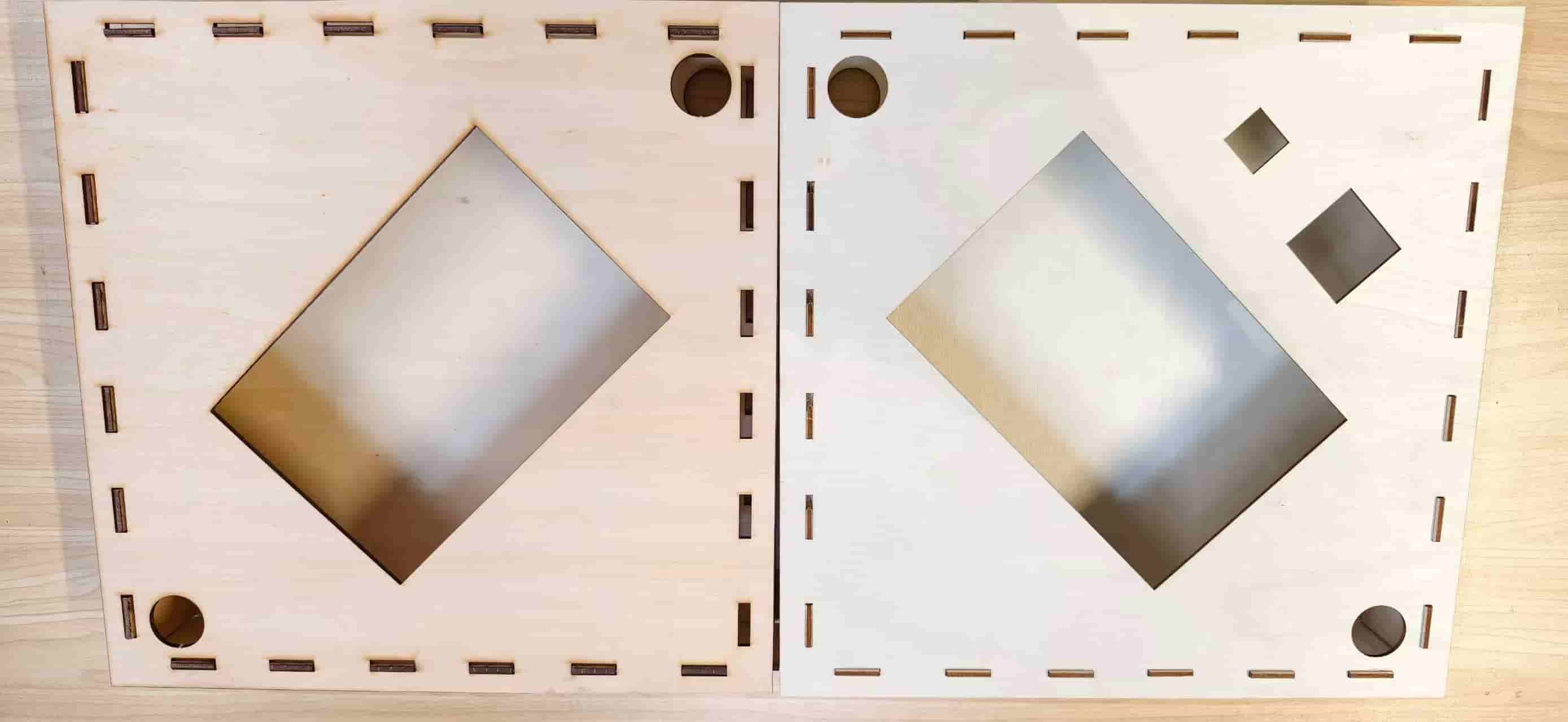
Two box tops compared: the left one is further along in assembly; the right one still has pencil measurements from layout.
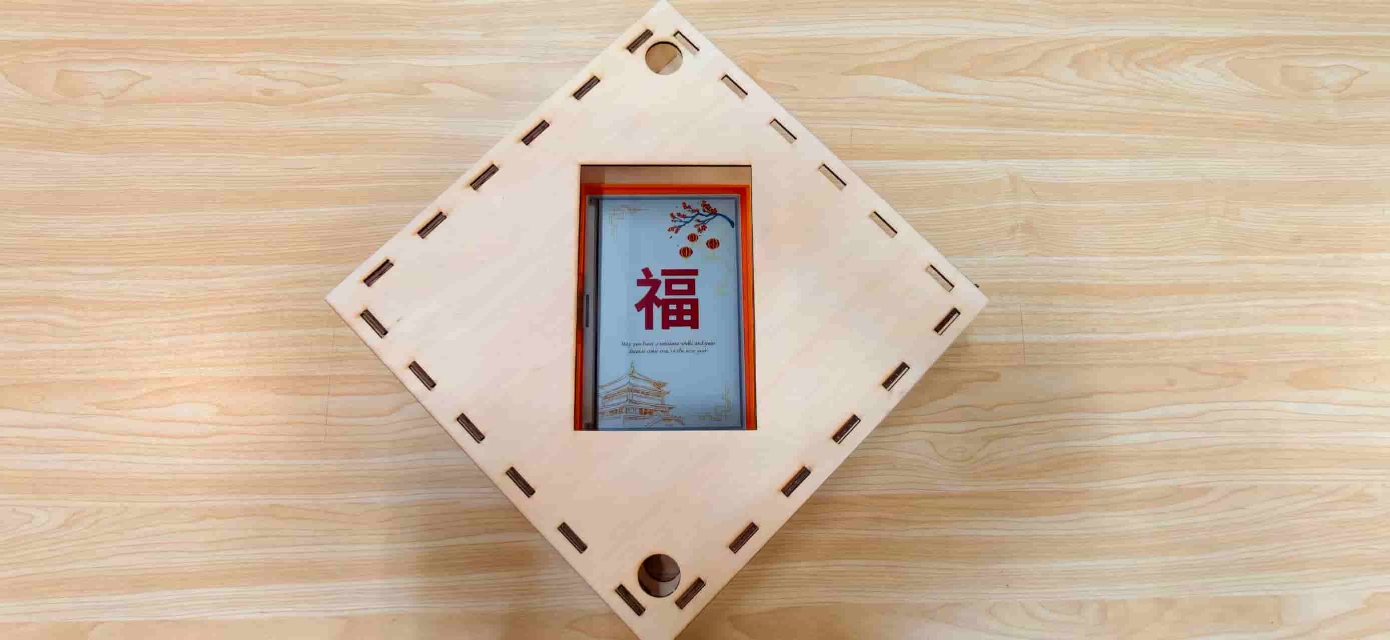
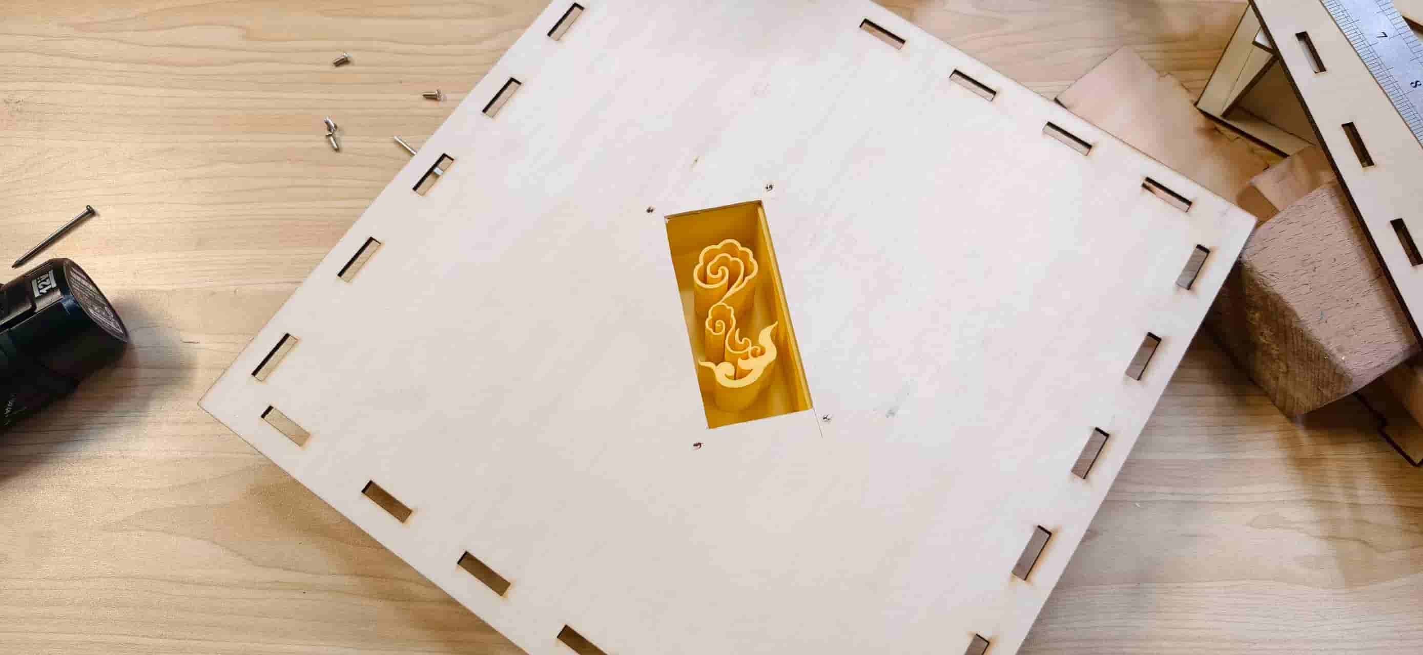
The first time I slipped a printed Fu card behind the ePaper window, the object finally felt real — not just a box with a hole, but a door decoration.
First Fu poster visible through the laser-cut window, with the orange ePaper holder recessed behind the plywood.
3D-printed holders inside the box
Every electronic module needed its own printed cradle. I could not treat them as an afterthought — if a holder was wrong, cables pulled, the display bowed, or the touch face sat at the wrong angle.
| Part | Iterations | Critical tolerance |
|---|---|---|
| ePaper holder | 6 | Panel seat depth, board standoff, FPC bend radius |
| OLED holder | several | 128 × 128 module snap-fit without bowing glass |
| Touch sensor holder | several | Sensor face aligned with visitor reach zone |
| Rear cloud support | 1 (from molding week) | Four screw points matching drilled plywood holes |
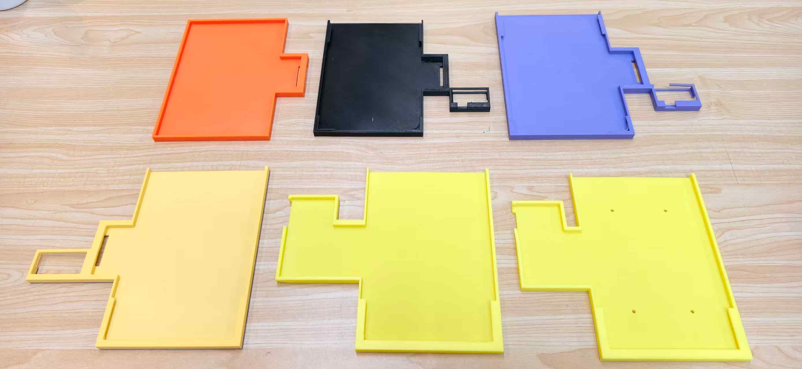
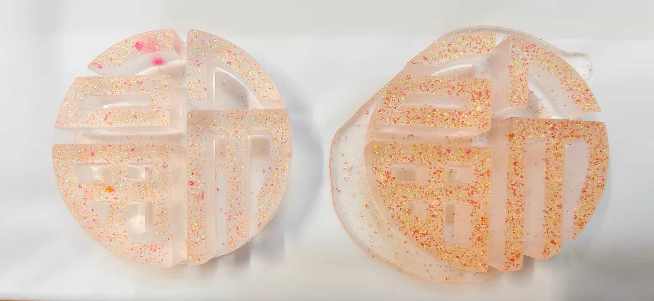
Six versions of the ePaper holder — orange, black, purple, and yellow prints showing how the tab geometry and mounting holes evolved.
The ePaper holder was the hardest part. I printed it in yellow PLA so misalignment would be visible against the wood grain. The side profile shows the standoff block that keeps the glass from pressing into the plywood.
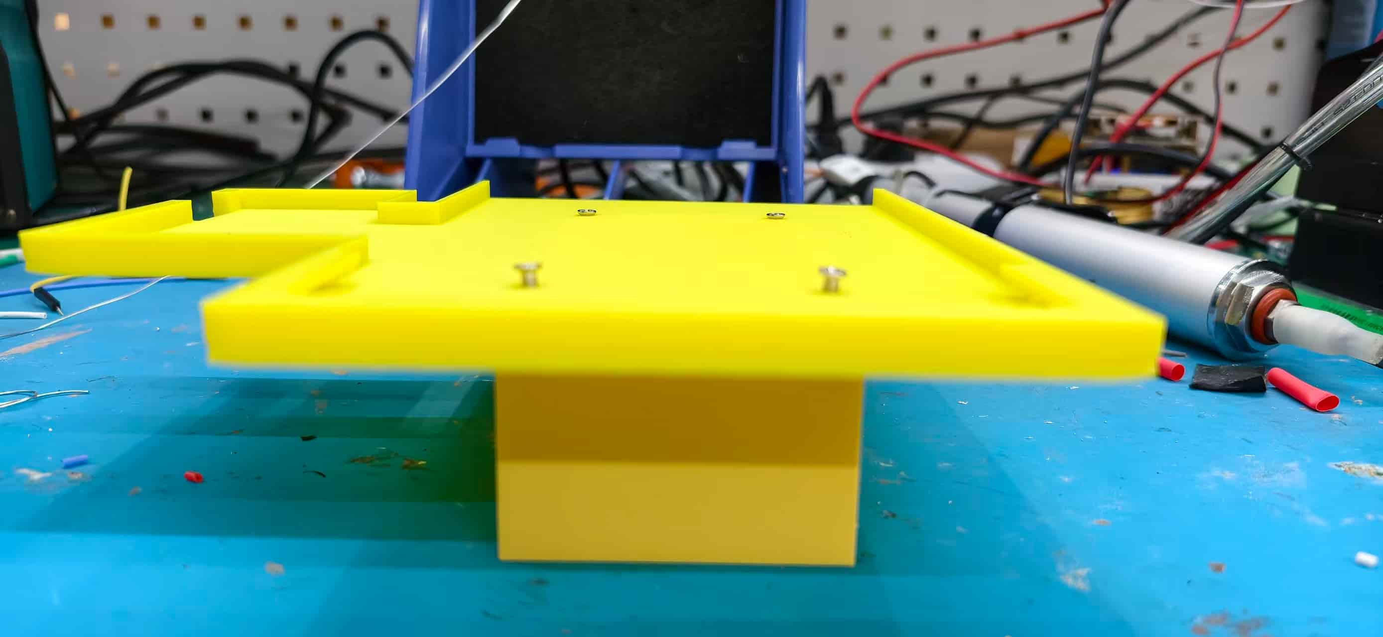
Side view of the ePaper holder — standoff height and panel seat depth were the dimensions I kept getting wrong in early prints.
For the smaller modules I added brass heat-set inserts so screws could go in and out during integration without stripping the plastic.
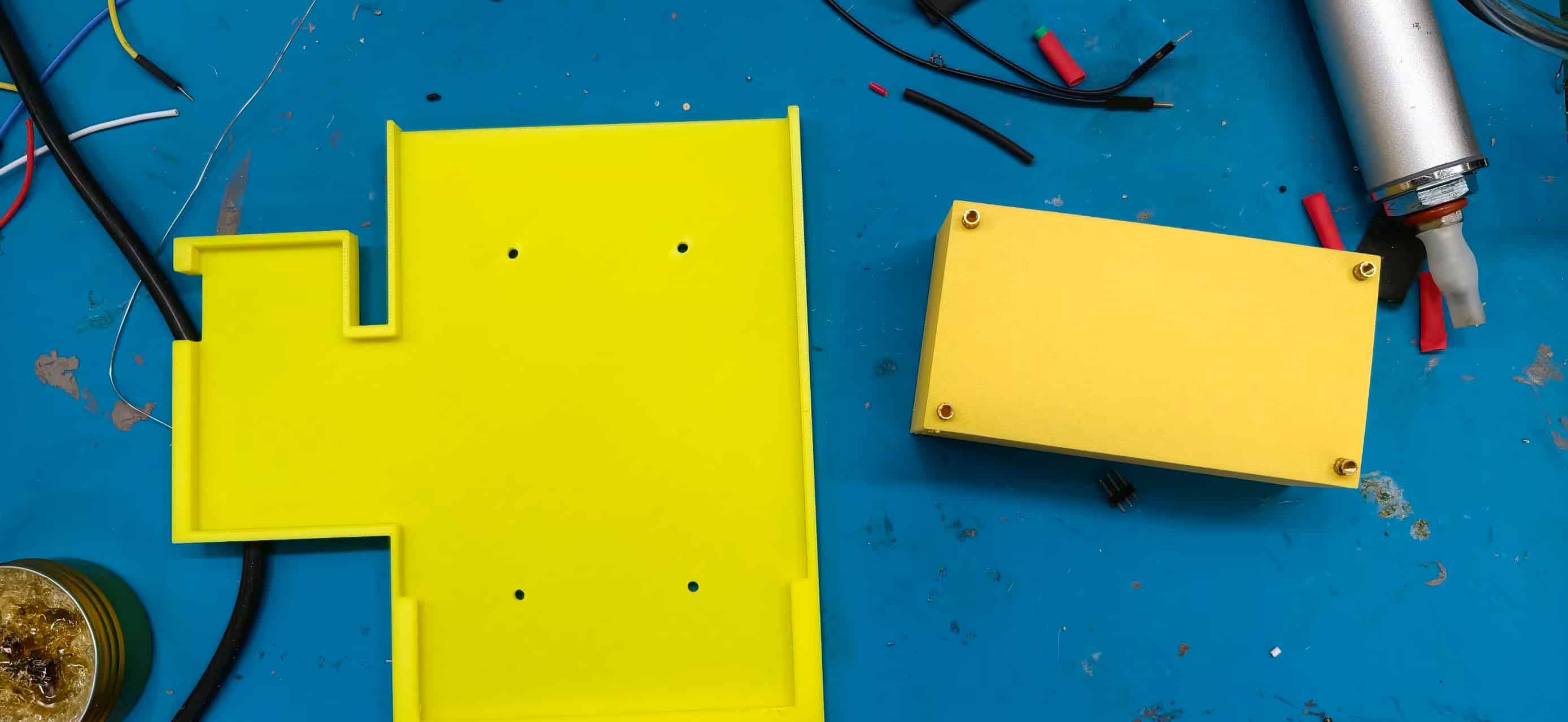
OLED and touch housings on the soldering bench — heat-set inserts in the corners for repeatable assembly.
Inside the box, the holders stack into the laser-cut slots like a small 3D puzzle.
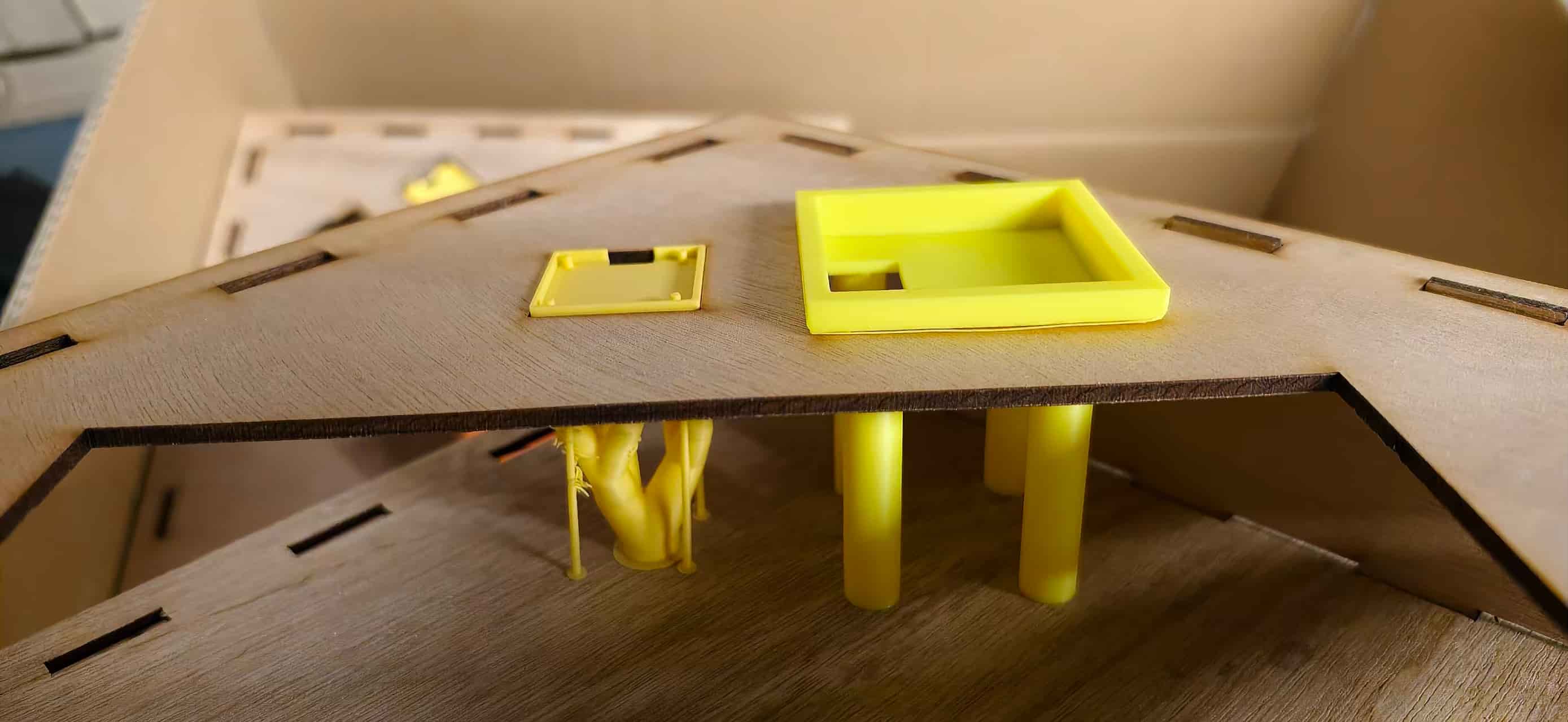
Looking into the assembled frame — yellow printed trays and standoffs nested inside the plywood shell.
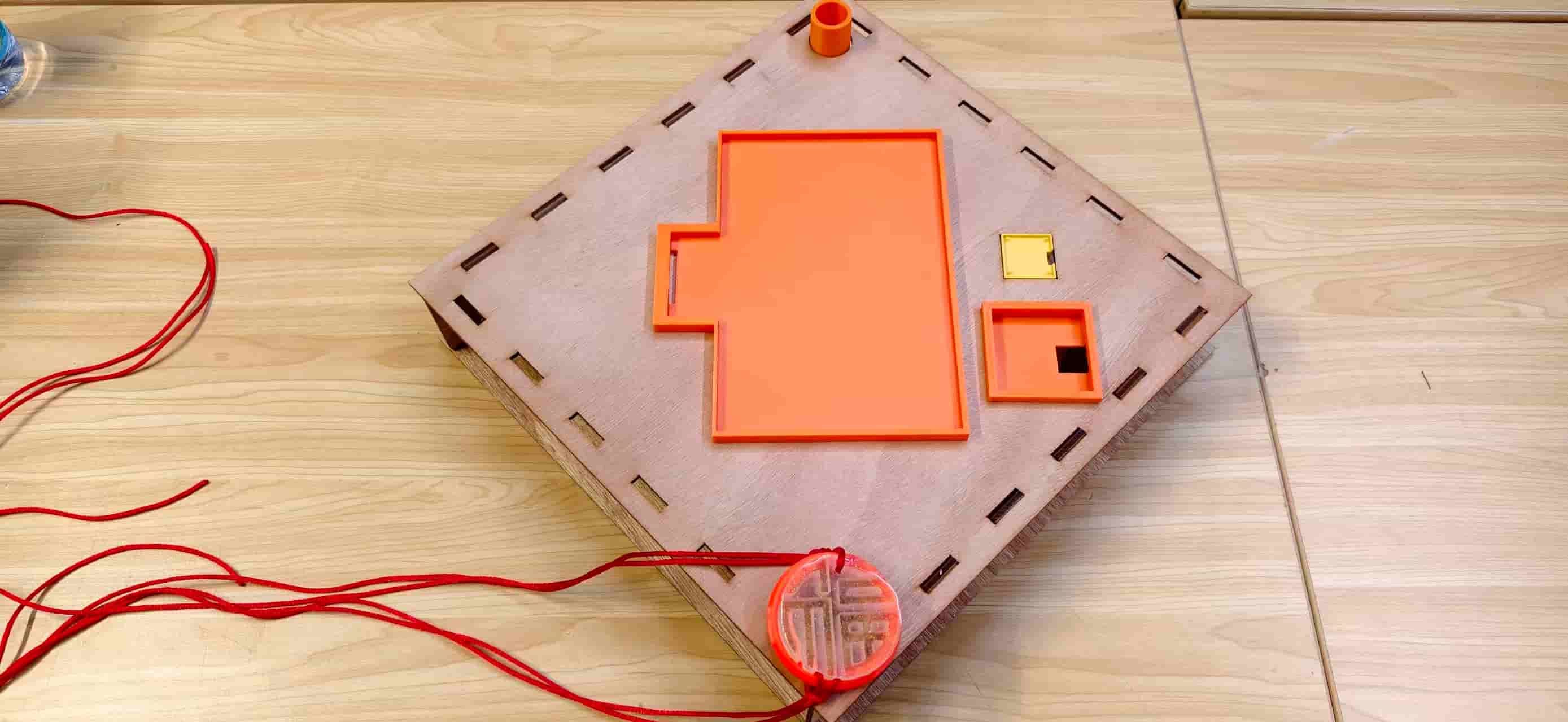
Early top-panel layout: ePaper tray, touch frame, and the resin Fu pendant hanging from the front edge.
Cloud back plate and resin Fu pendant
The rear ruyi cloud structure came from Week 14 — Molding and Casting. I had already designed the cloud master, printed mold boxes, and cast resin Fu pendants. During integration week, that work became structural instead of decorative.
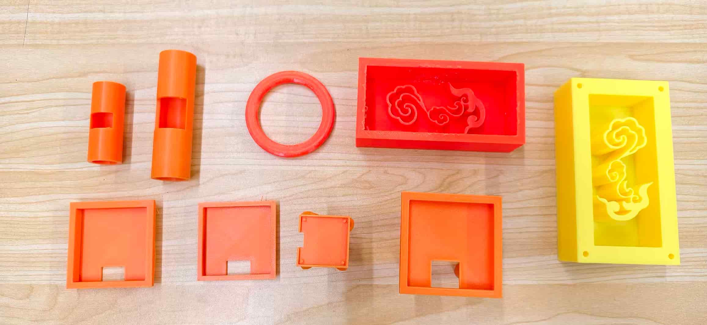
Cloud mold parts from Week 14 — the yellow master and orange mold shells that produced the back-plate pattern.
The cloud plate screws through the wooden rear panel into printed standoffs. That replaced glue-only assembly and made it possible to open the object during integration without destroying the frame.
The cloud pattern visible through the rear panel cutout — a decorative element that also stiffens the box.
For the hanging pendant I cast two resin Fu discs — one clean, one with flash from an imperfect seal — then drilled a cord hole and threaded red string through.
Two resin casts side by side — the left one clean, the right one with overflow flash from the mold.
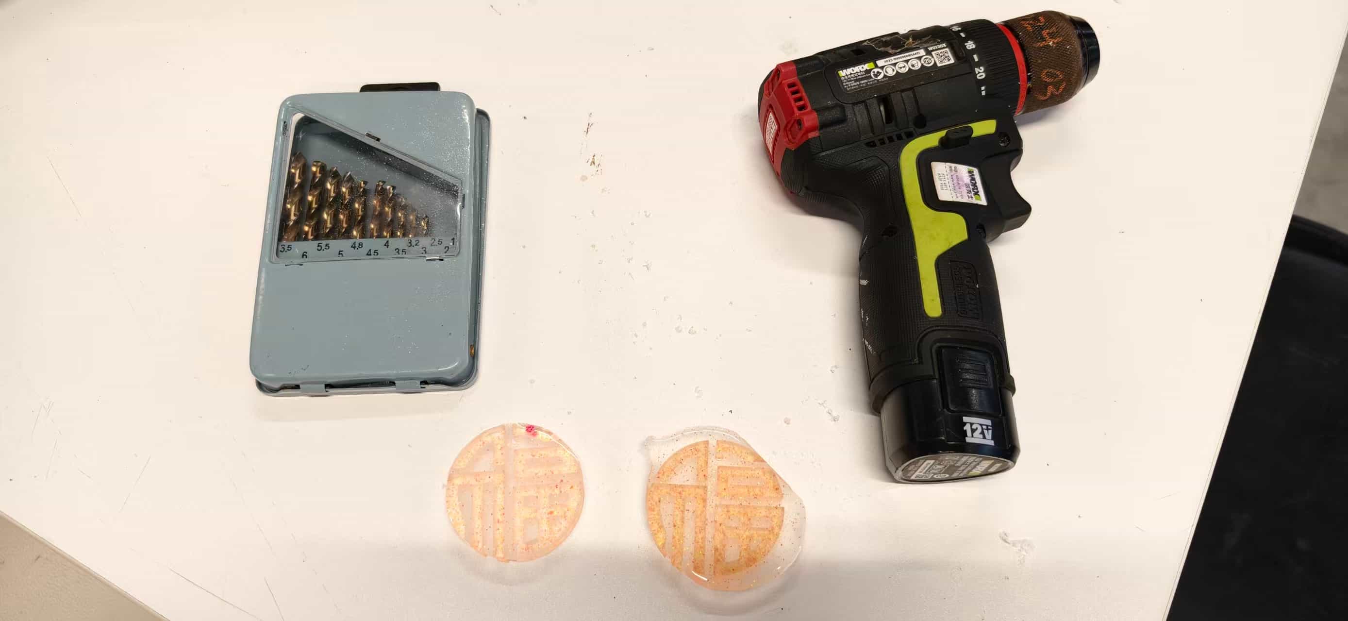
Drilling the cord hole — choosing a bit size that would not crack the thin resin edge.
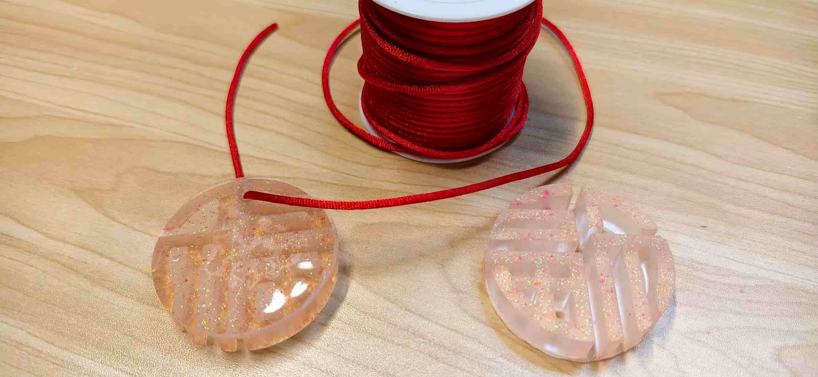
Finished pendant on red cord next to the spool — glossy vs. matte finish from two pour attempts.
The pendant became the small touch of tradition on an otherwise very digital object.
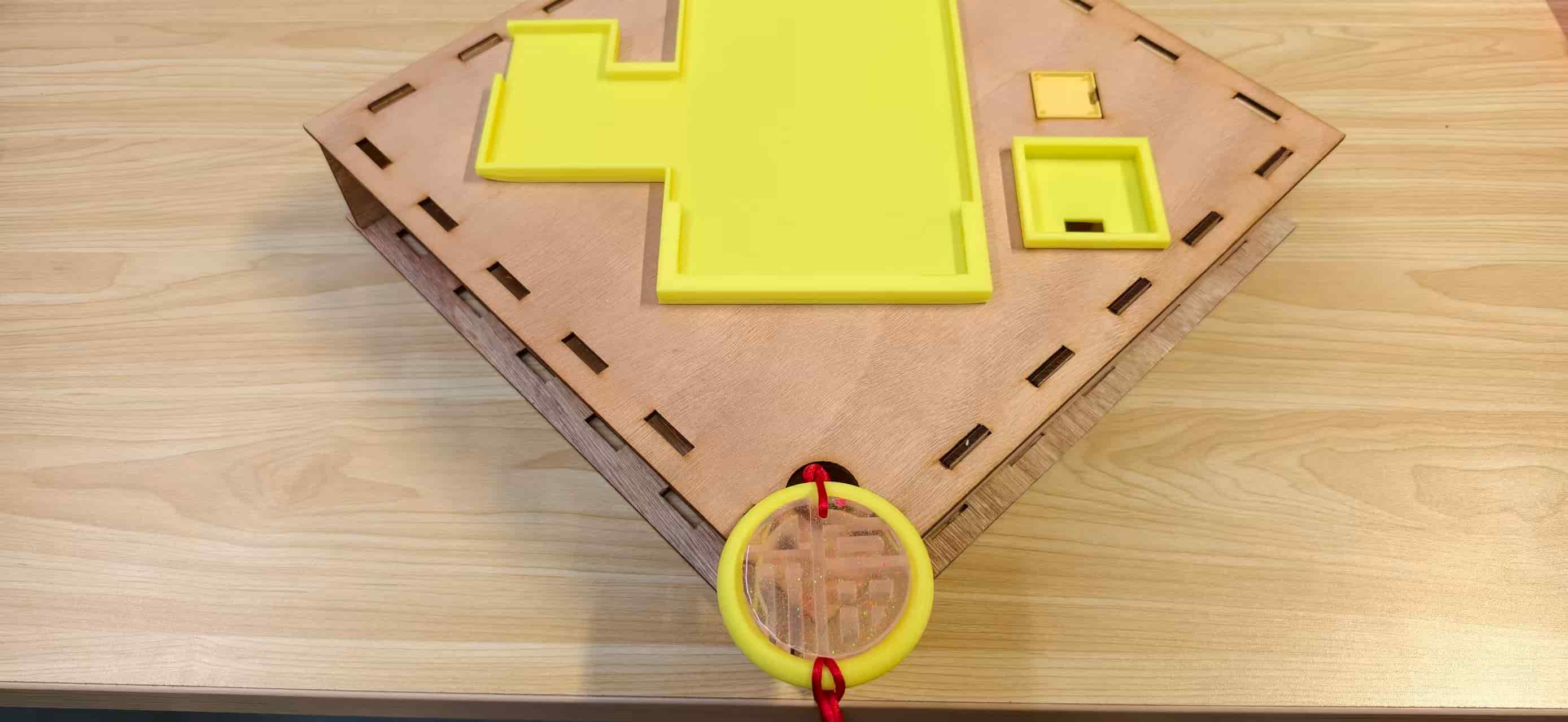
Top panel with holders mounted and the resin Fu pendant hanging from the front — the moment the mechanical and cultural layers clicked together.
Cable routing and service access
Integration testing failed repeatedly when jumper wires pulled loose during frame fitting. Final assembly routes I2C (OLED) and touch cables with strain relief through the printed holders, and keeps the S3 + EE04 stack accessible from the rear for USB flashing. I learned to leave one side of the box unscrewed until the very end of the week — I opened and closed it more times than I can count.
Key Files Reference
All integration source lives under static/img/interface/ in this repository:
interface/
├── server.js              ← Node.js Express backend
├── index.html             ← IoT dashboard (Tailwind CSS)
├── convert.py             ← PNG → images.h converter
├── images.h               ← shared poster C arrays (root copy)
├── EE04_S3_Poster/
│   ├── EE04_S3_Poster.ino ← S3 main firmware
│   ├── driver.h           ← panel + board combo config
│   └── images.h           ← poster arrays (flashed copy)
├── c3_touch_sender/
│   └── c3_touch_sender.ino ← C3 touch + OLED firmware
├── poster1.png ~ poster3.png ← source artwork
├── read_serial.py         ← debug serial monitor helper
└── start_server.bat       ← Windows quick-launch for demo
API summary
| Method | Endpoint | Body / query | Effect |
|---|---|---|---|
GET | /api/status | ?device=s3 optional | Returns full state; S3 poll updates devices.s3 |
POST | /api/status | status=coming | C3 touch → poster 3, lastEvent=touch |
POST | /api/status | poster=1|2|3 | Web selection → lastEvent=web |
POST | /api/reset | — | currentPoster=1, lastEvent=reset |
Running the integrated system
- Connect the laptop to
X.factory2.4Gand note its IP (e.g.192.168.100.18). - Update
serverUrlin both.inofiles if the IP changes. - Start the server:
node server.js→ listen on port 3000. - Flash C3 and S3 firmware; confirm Serial Monitor shows WiFi connected.
- Open
http://<laptop-ip>:3000— verify device pills turn green. - Touch the sensor: OLED greets → toast appears → ePaper switches to poster 3.
What I Learned
| Topic | Lesson |
|---|---|
| Incremental integration | Bring up display, then assets, then server, then one device, then both — never all at once |
| ePaper lifetime | Poll + refresh on change only; avoid library sleep if wake is unreliable |
| WiFi band | Confirm 2.4 GHz SSID before debugging HTTP |
| SPI vs. WiFi | Disconnect WiFi during long SPI transfers on ESP32-S3 |
| UI state | Edge-trigger notifications (lastKnownEvent), not level-trigger |
| Mechanical fit | Budget kerf, label cut orientation, print holder clearances for cables |
| Fixed server IP | Simplifies firmware; document it clearly for reproducible demos |
Week 16 turned the Fu project from a collection of weekly exercises into one inspectable system. A visitor can touch the door module, a resident can see proof on the web, and the ePaper updates without manual reflashing.
The hardest work was not any single API call. It was making physical tolerances, firmware timing, and interface behavior agree at the same time — and having the patience to fix them one layer at a time. Integration week felt messy while I was inside it, but looking at the finished bench setup, I can see how each earlier week contributed something essential. That is probably the real point of this assignment: not perfection on the first try, but a system you can explain, open, debug, and demo with confidence.
Downloadable Files
Paths below are repository-relative (same style as my other weekly pages). In GitLab, open the file and use Download or Raw, or clone the repo to get everything.
Firmware and server (integrated system)
- Node.js server
- Web dashboard —
static/img/interface/index.html(served bynode server.js) - PNG → C array converter
- Poster bitmaps (
images.h) - C3 touch sender firmware
- S3 ePaper poster firmware
- S3 board + panel config (
driver.h) - Windows quick-launch script
- Serial debug helper
Laser-cut frame (Fu box)
Earlier touch/OLED test