Appearance
Week 3 - Fab Academy - Computer controlled cutting
Assignments
Group Assignment
- Do your lab's safety training
- Characterize your lasercutter's focus, power, speed, rate, kerf, joint clearance and types
Individual Assignment
- Cut something on the vinylcutter
- Design, lasercut, and document a parametric construction kit, accounting for the lasercutter kerf, which can be assembled in multiple ways, and for extra credit include elements that aren't flat
Group Working
My group work is attached here: https://fabacademy.org/2025/labs/unnc/assignments/week3/week03.html
Individual Working
Parametric Modeling
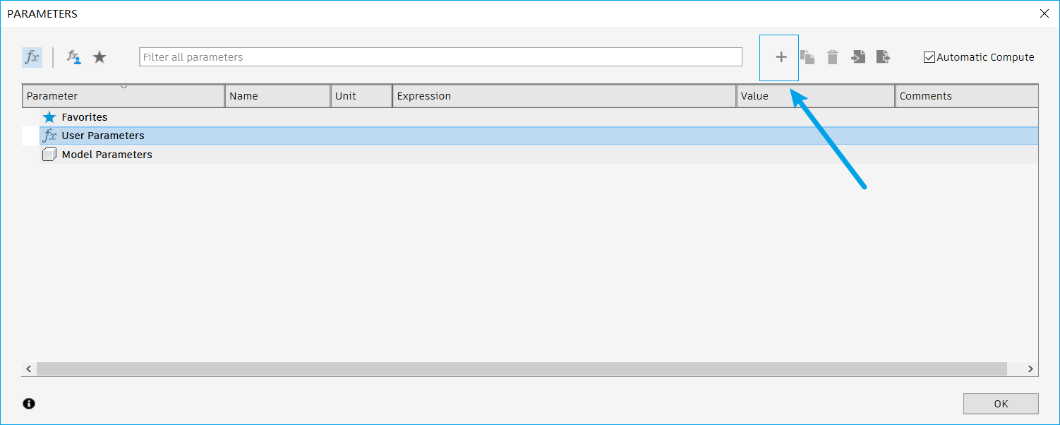
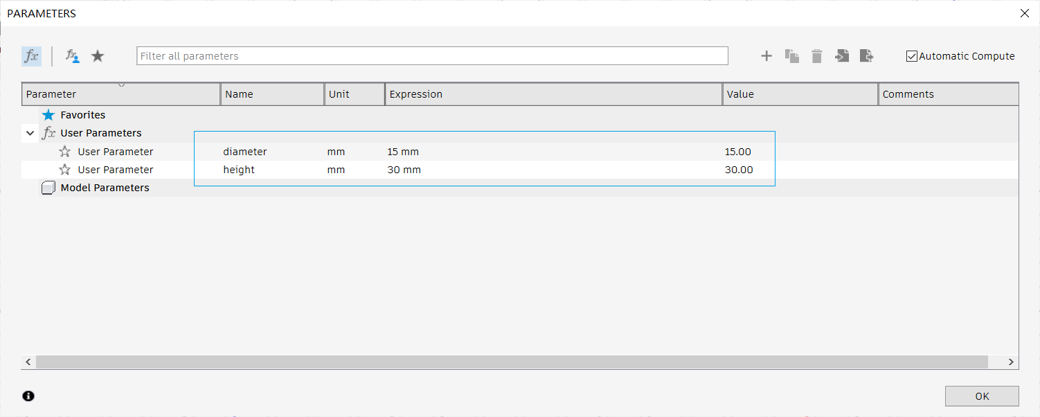
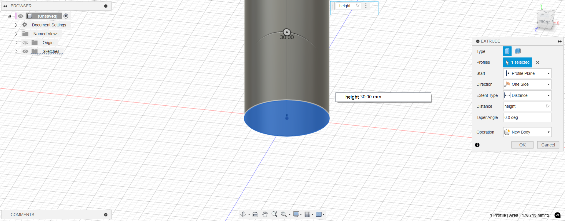
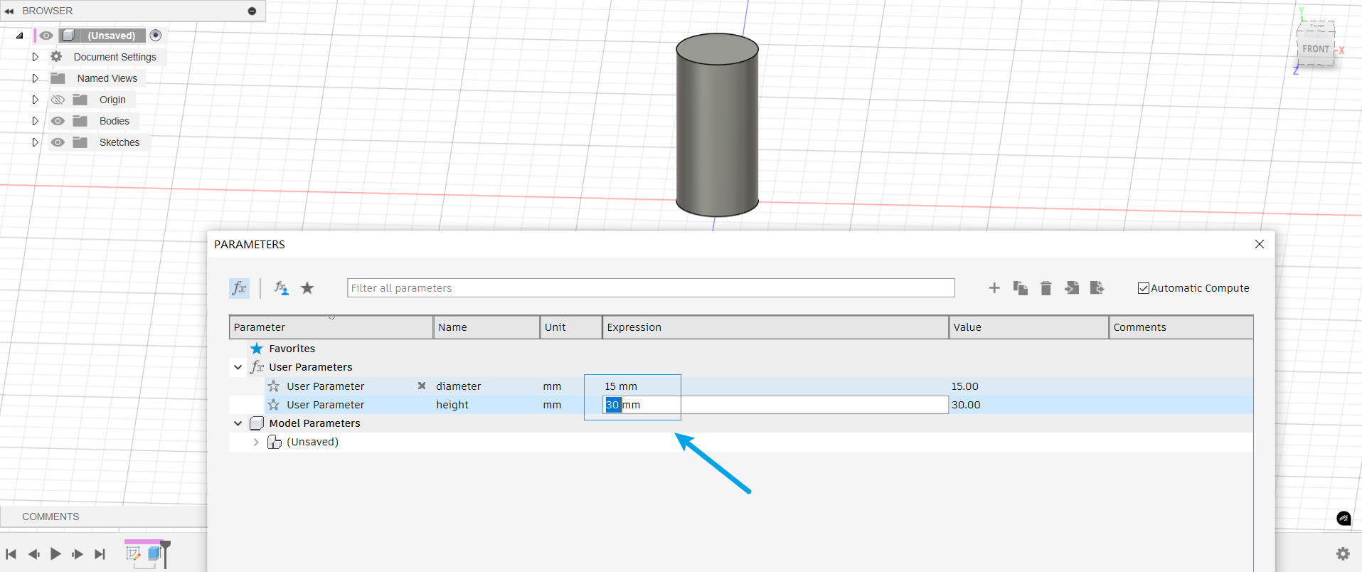
The basic workflow of parametric modeling is as follows: First, enable the parameter setting feature in the modeling software—such as by opening "Change Parameters" in Modify. Then, define two key parameters: diameter and height. These parameters allow you to flexibly control the model's dimensions by adjusting their values, enabling easy modifications and design updates. 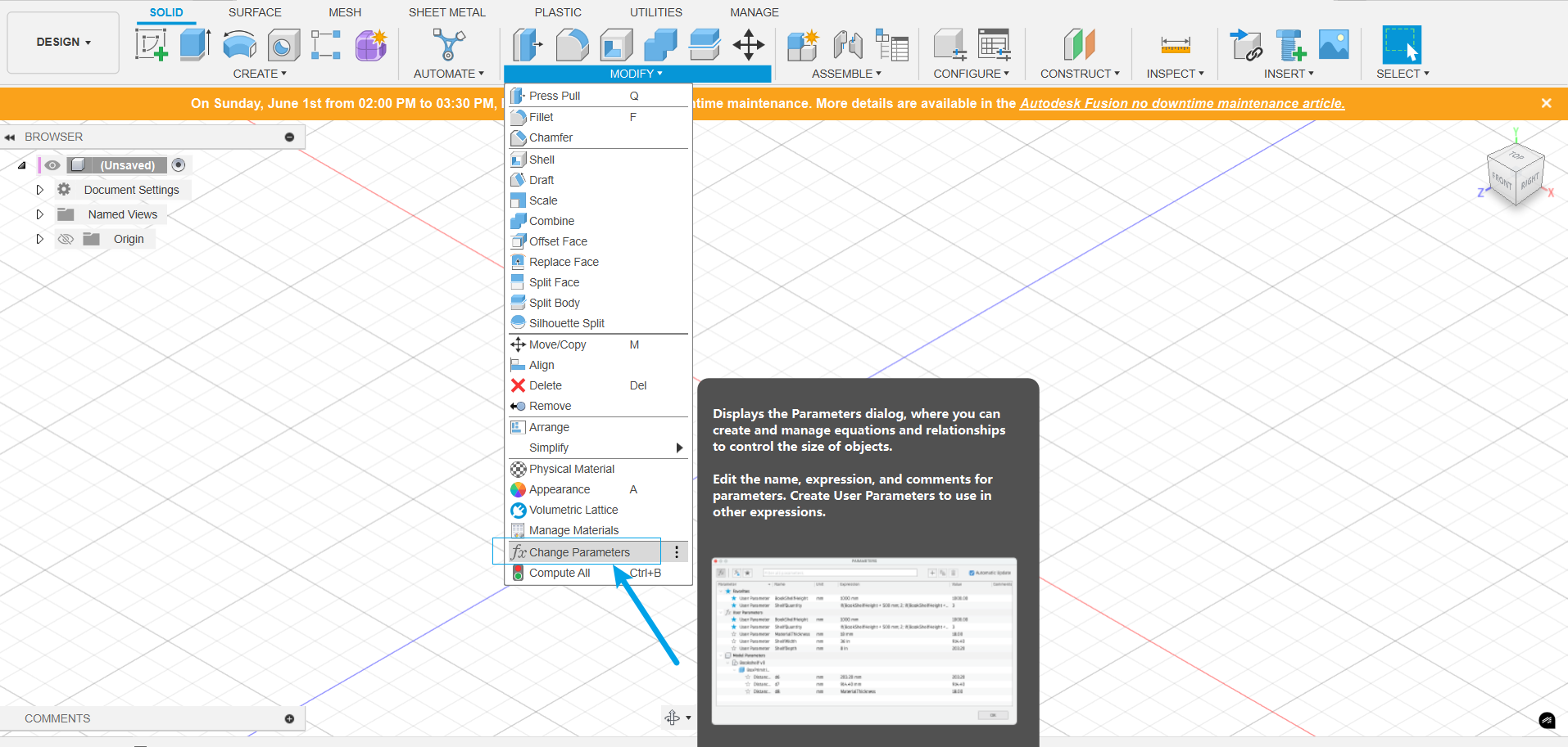
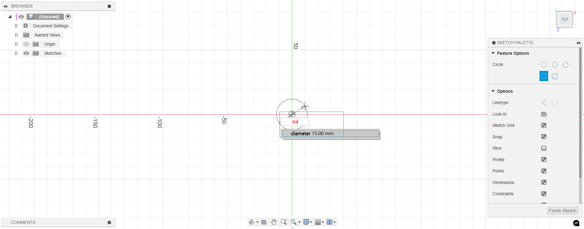
Next, create a new sketch and draw a circle, assigning its diameter to the previously defined parameter diameter. Then, perform an extrusion operation and set the extrusion height to the parameter height.
After that, simply changing the parameter values allows you to generate models of different sizes, enabling quick design modifications.
Snowflakes
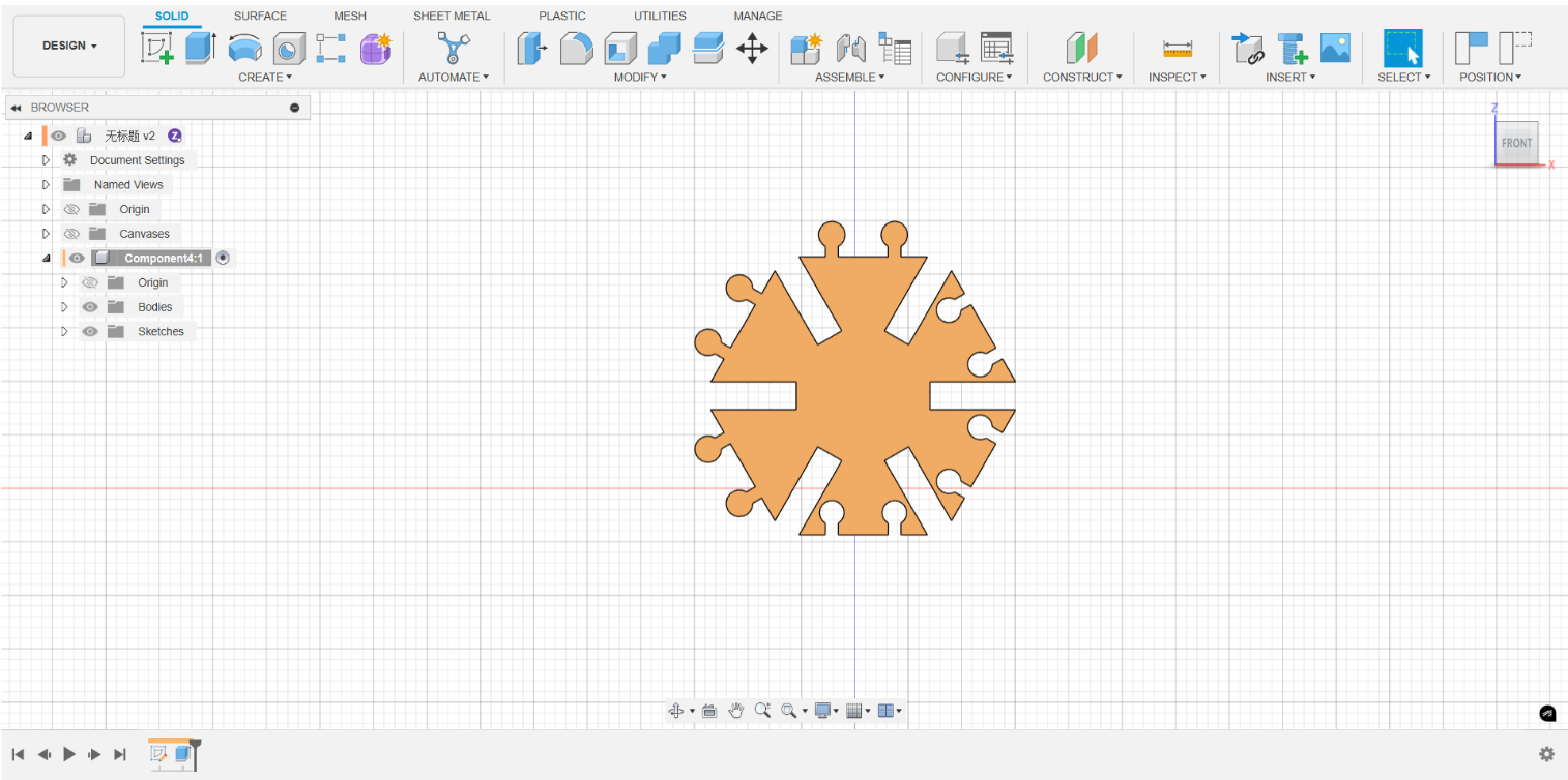
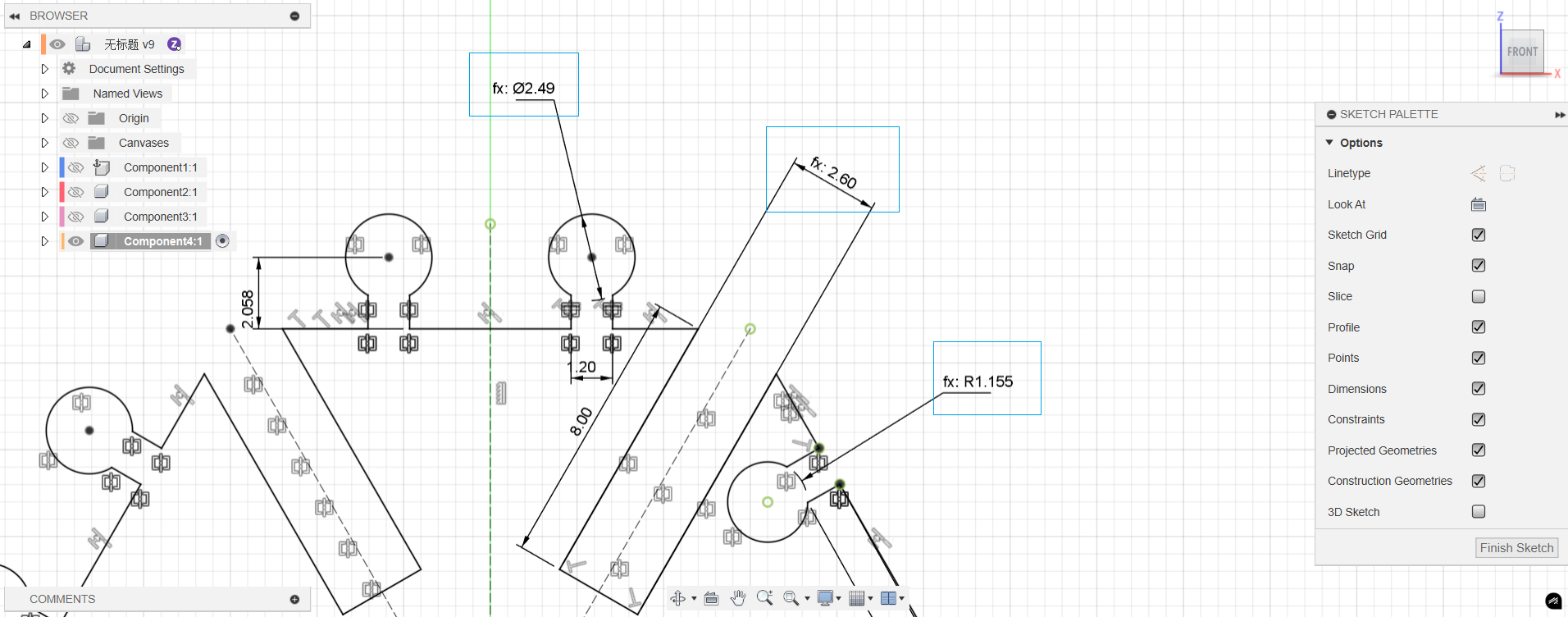
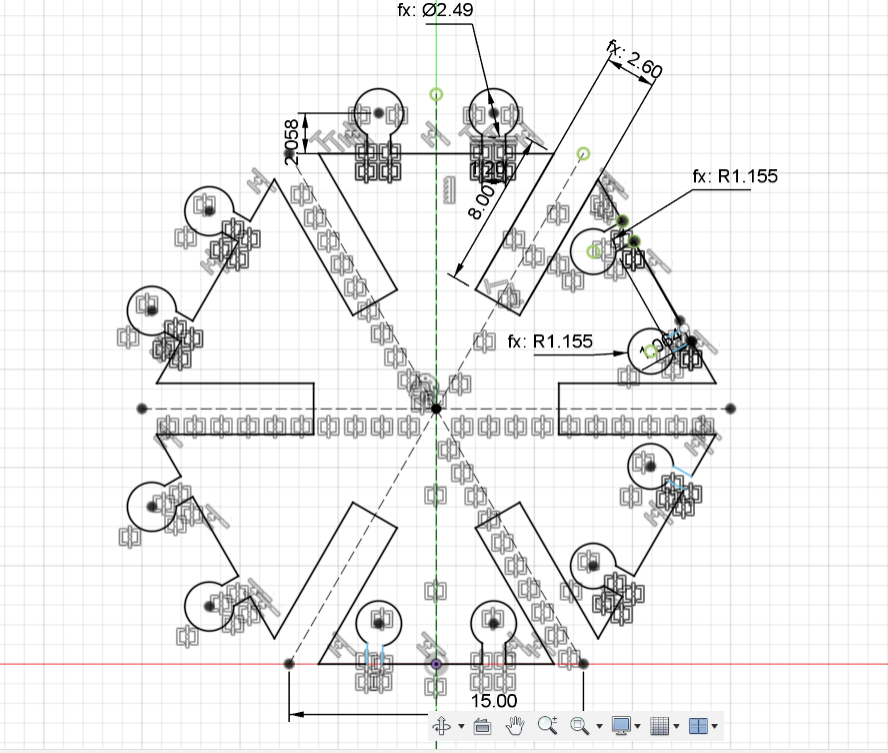
A hexagonal modular pattern was designed in Fusion 360, which can be assembled into various component structures using both snap-fit and interlocking mechanisms. The model adopts a parametric design approach, allowing for flexible adjustment and precise control of dimensions through predefined parameters.
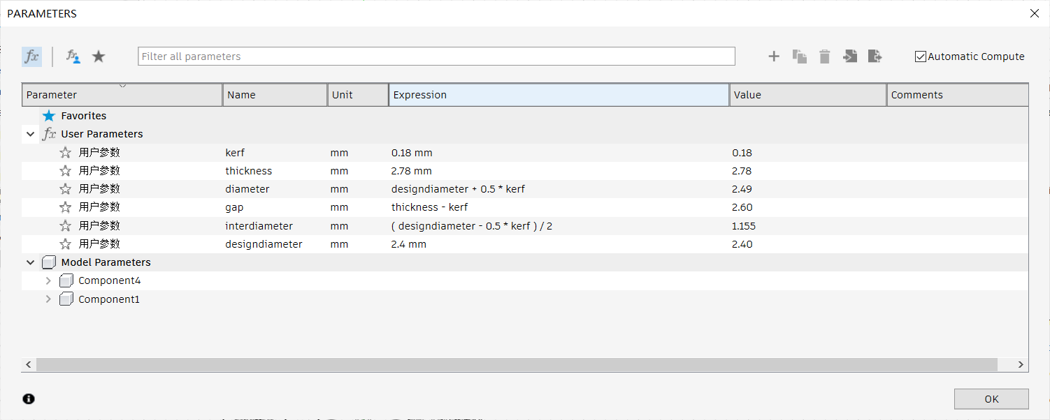
A parameter called kerf is introduced during the model design process to represent the material loss caused by laser cutting (i.e., the laser beam radius). By measuring the actual kerf width of the laser cutting machine and inputting it as the kerf parameter value, the system automatically adjusts the gap and fit between the parts. This ensures proper compatibility and stability during actual manufacturing and assembly.
I defined two parameters in the design: kerf and thickness. Among them, kerf is used to represent the slit width (i.e. processing error) caused by material ablation during laser cutting. It is initially set to 0.18mm and can be adjusted later according to the actual spot radius of the laser to ensure the dimensional accuracy and assembly effect of the parts after cutting. Thickness represents the thickness of the material, which is used to control the overall size and connection strength of the structure.
The formula is designdiameter+0.5*kerf, designdiameter is the diameter of the circle in design(data is 2.4mm), and kerf is the diameter of the laser.
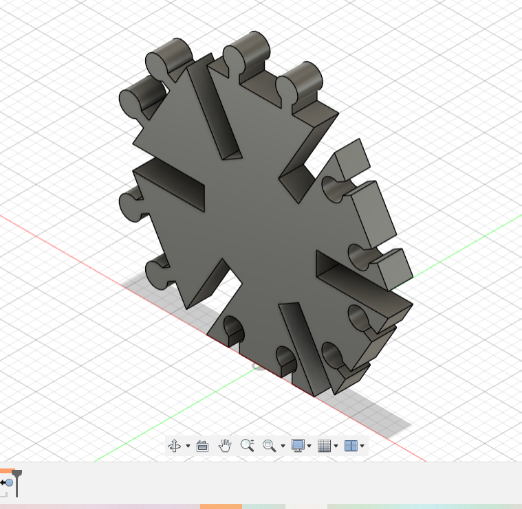
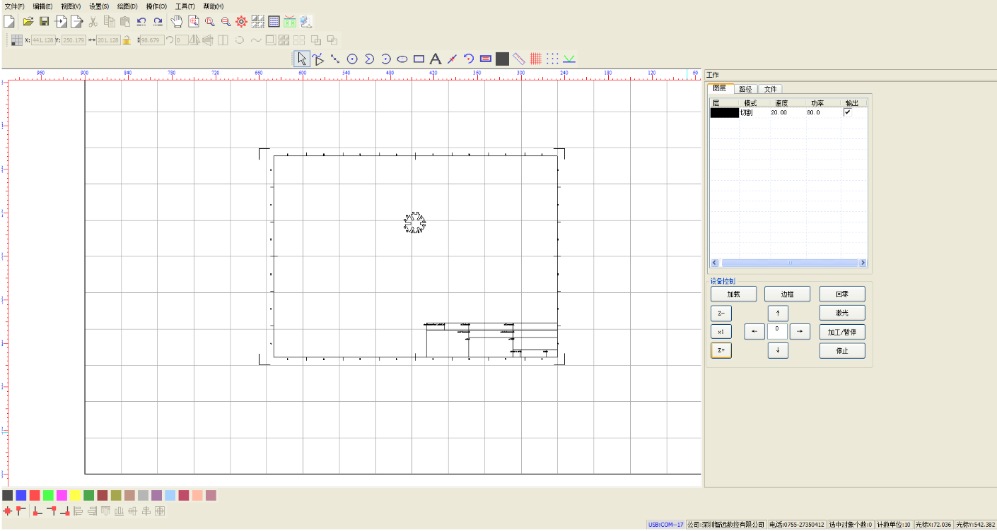
Export the model as a DXF file in Fusion 360 and import it into the laser cutting software for subsequent cutting path setting and processing operations.
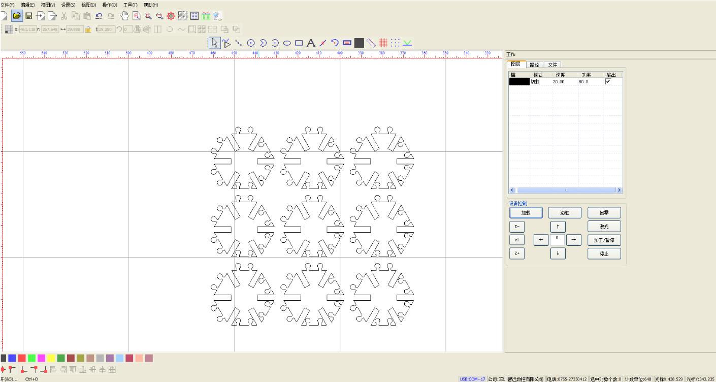
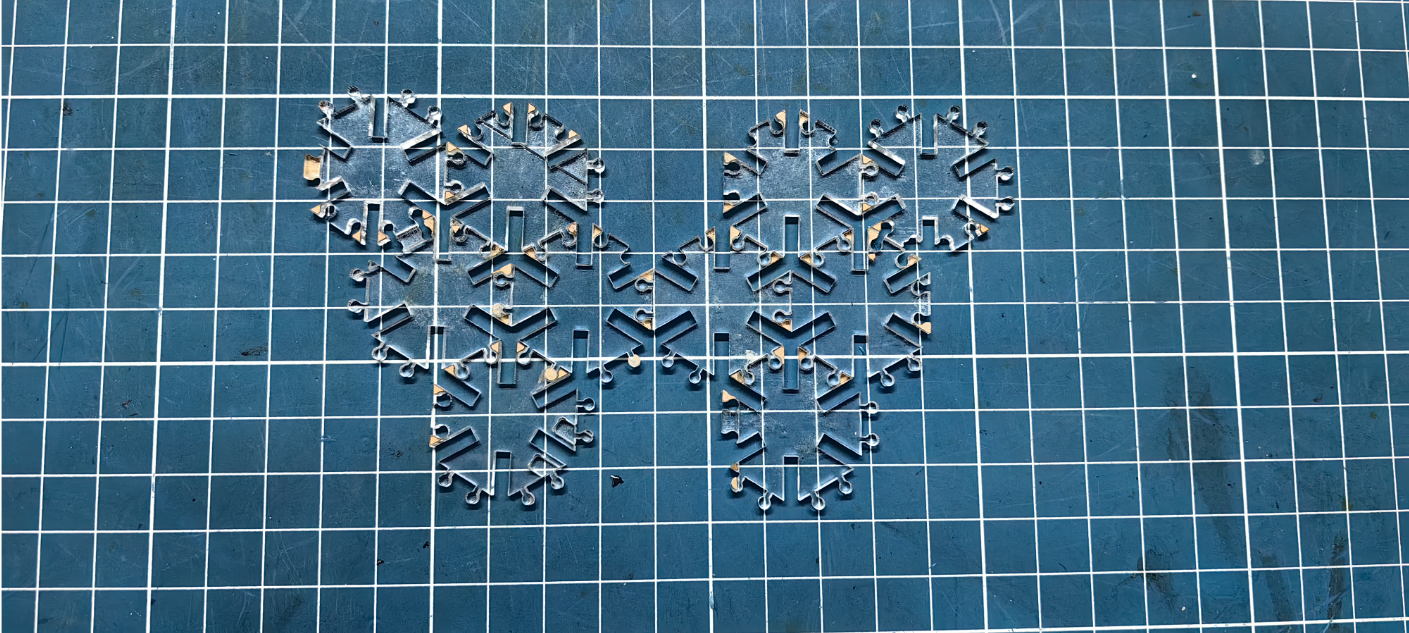
Assemble as follows: 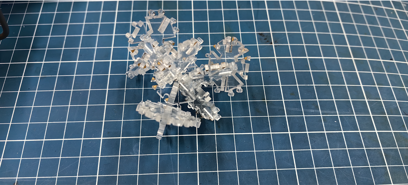
Laser Engraving Machine
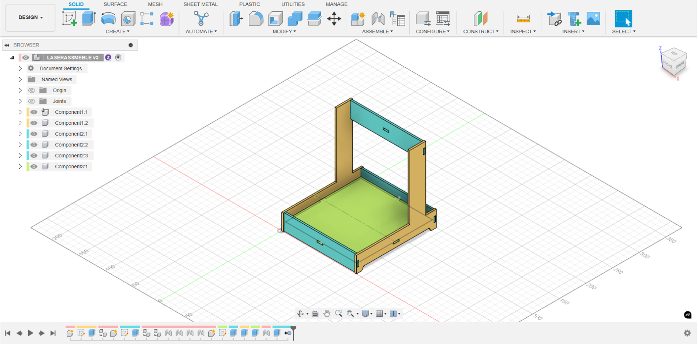
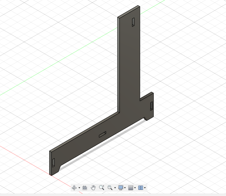
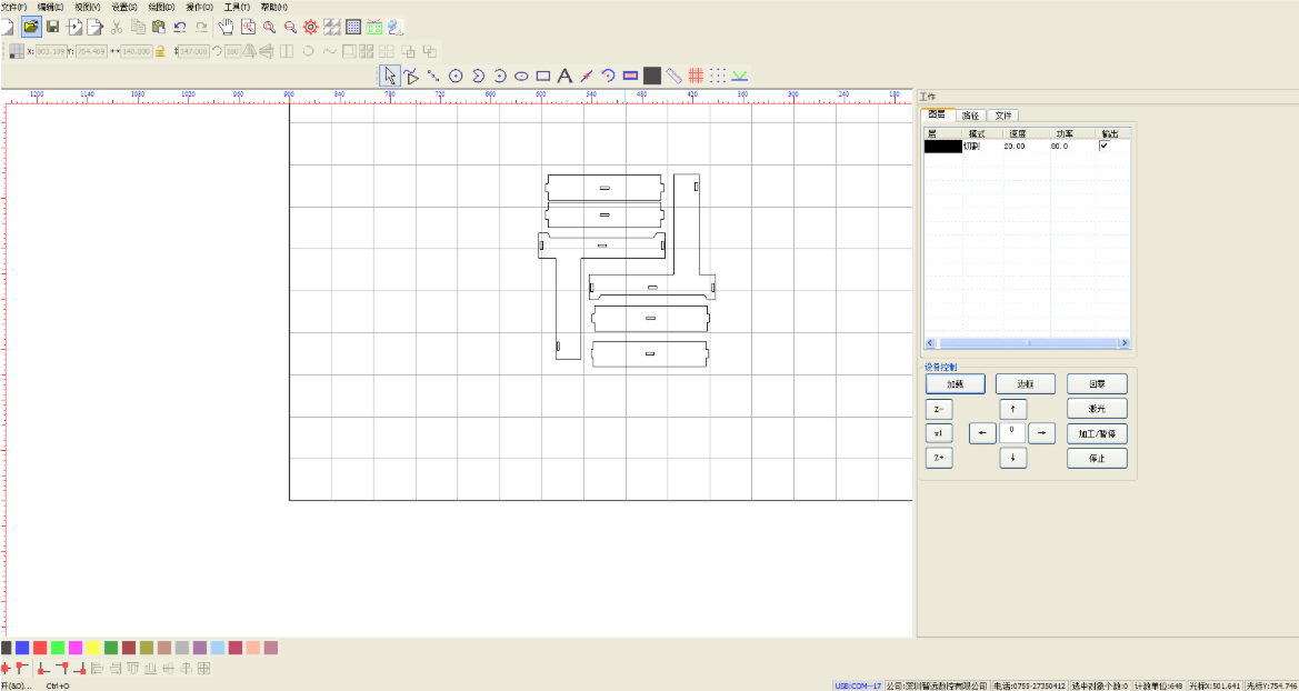
The following is the laser cutting machine processing version of the micro laser engraving machine. All components can be quickly assembled and disassembled through the plug-in connection structure.
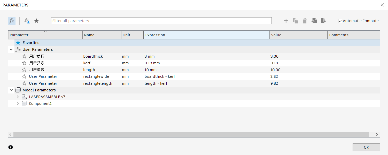
Setting kerf parameters:
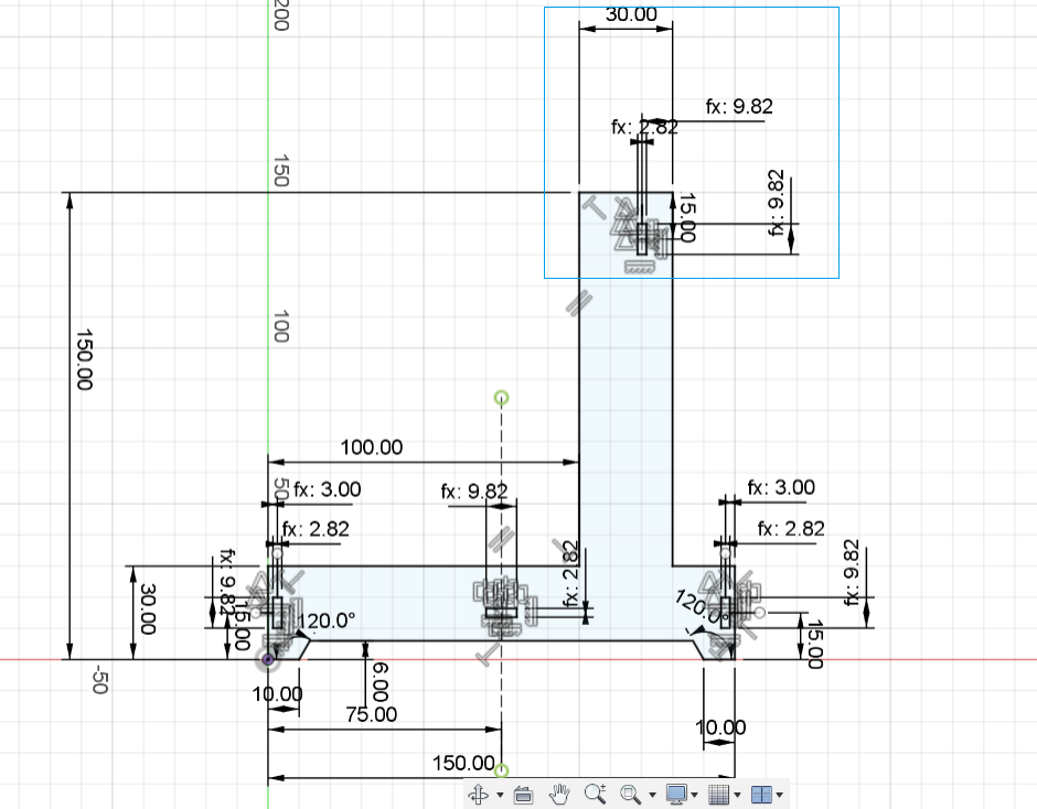
During the design process, I defined three key parameters: boardthick, kerf, and length, which are used to represent the thickness of the material, the dimensional loss caused by the laser cutting process, and the target length of the part.
Boardthick is used to set the actual thickness of the plate, ensuring that the dimensions of the structure accurately match the material specifications.
Kerf represents the material loss (kerf width) caused by high-temperature ablation during laser cutting. It is initially set to 0.18mm, but it can be adjusted based on the actual measurement results of the laser equipment to compensate for any cutting errors.
Length is used to define the design length of the structure or component, supporting flexible modification and modular combination for adaptable designs.
During the specific modelling, to ensure that the cut plate can be smoothly inserted into the matching structure, I used the parameterized formula length-kerf to define the size of the slot. For example, when the plate thickness is 3mm, the width of the slot is set to board thickness, and the length is set to length-kerf. This approach ensures a good fit and assembly performance between parts while accounting for the material loss due to laser cutting.
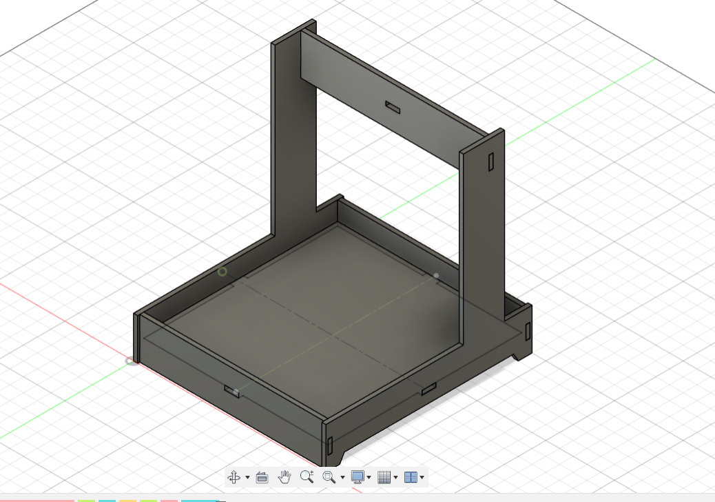
The assembly effect is as follows: 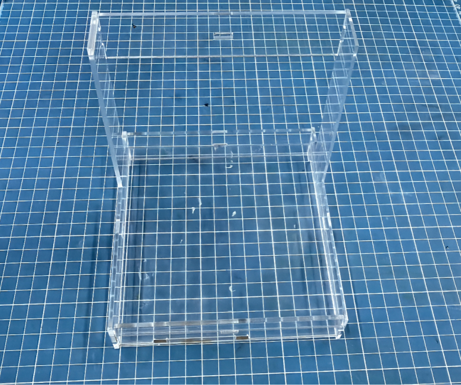
Vinyl Cutting
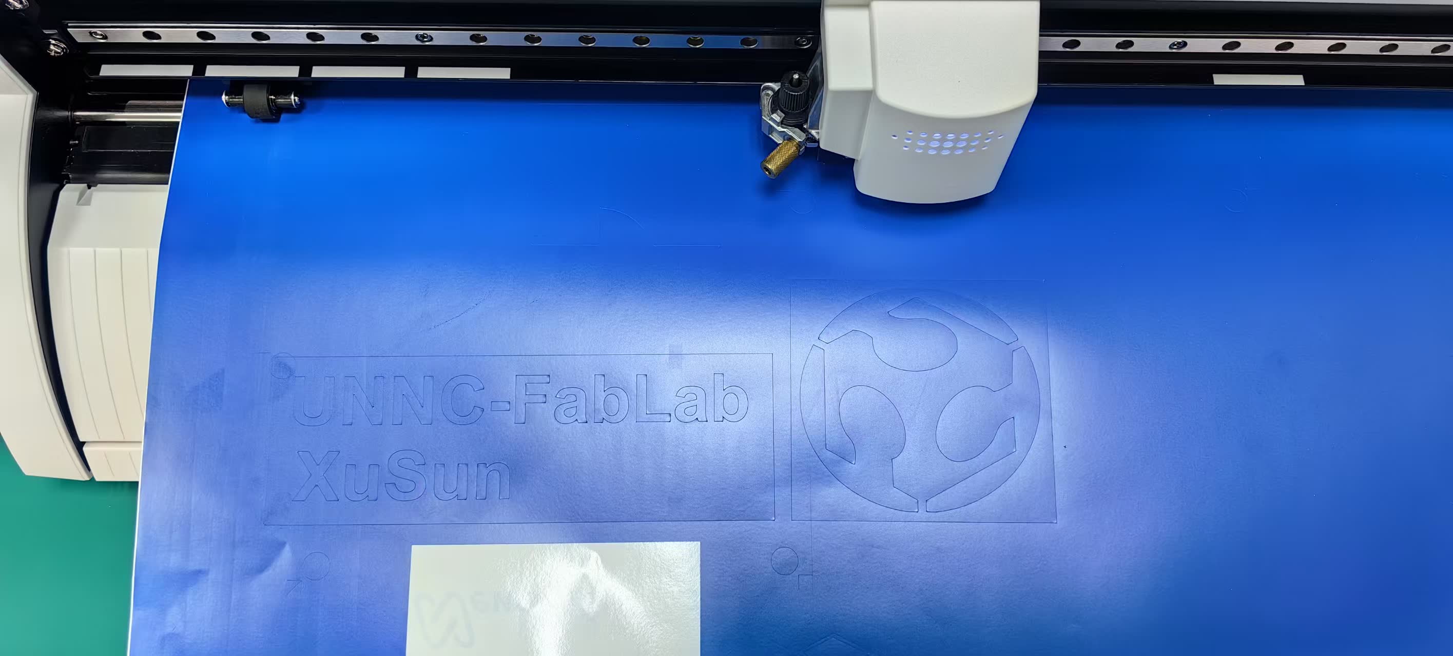
Vinyl cutting is a process that uses a cutting machine to accurately cut vinyl materials according to the design pattern. It is often used to make stickers, labels, wall stickers and clothing heat transfer patterns. This process is suitable for vinyl films of various colors and materials. It has the advantages of high precision, low cost and easy operation. It is widely used in advertising, handicrafts and personalized customization.
We have a vinyl cutting machine, model GS-24, which allows us to create intricate vinyl designs with a high degree of precision. 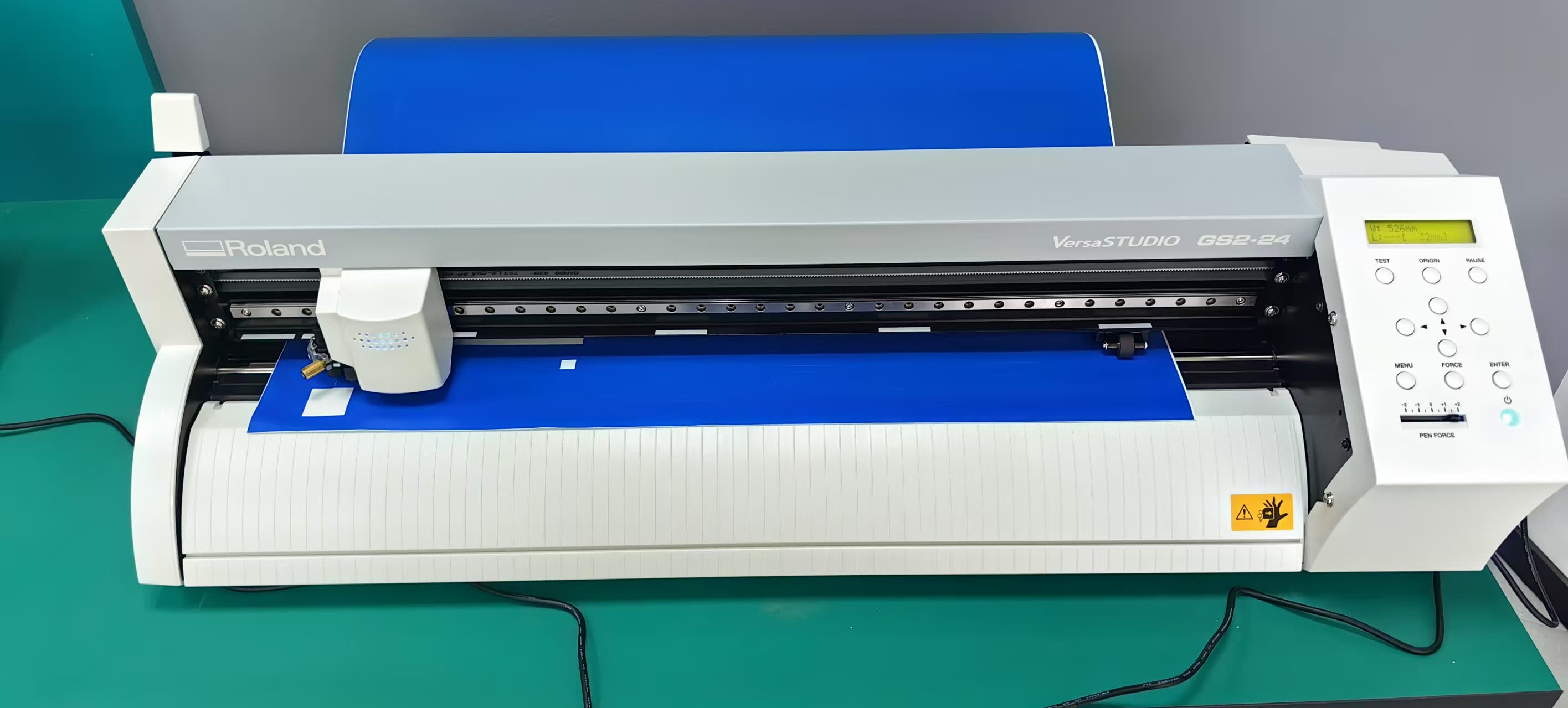
User Manual: https://files.rolanddga.com/files/gs-24_usersmanual/responsive_html5/index.htm#t=GS-24_USE_EN_04.html
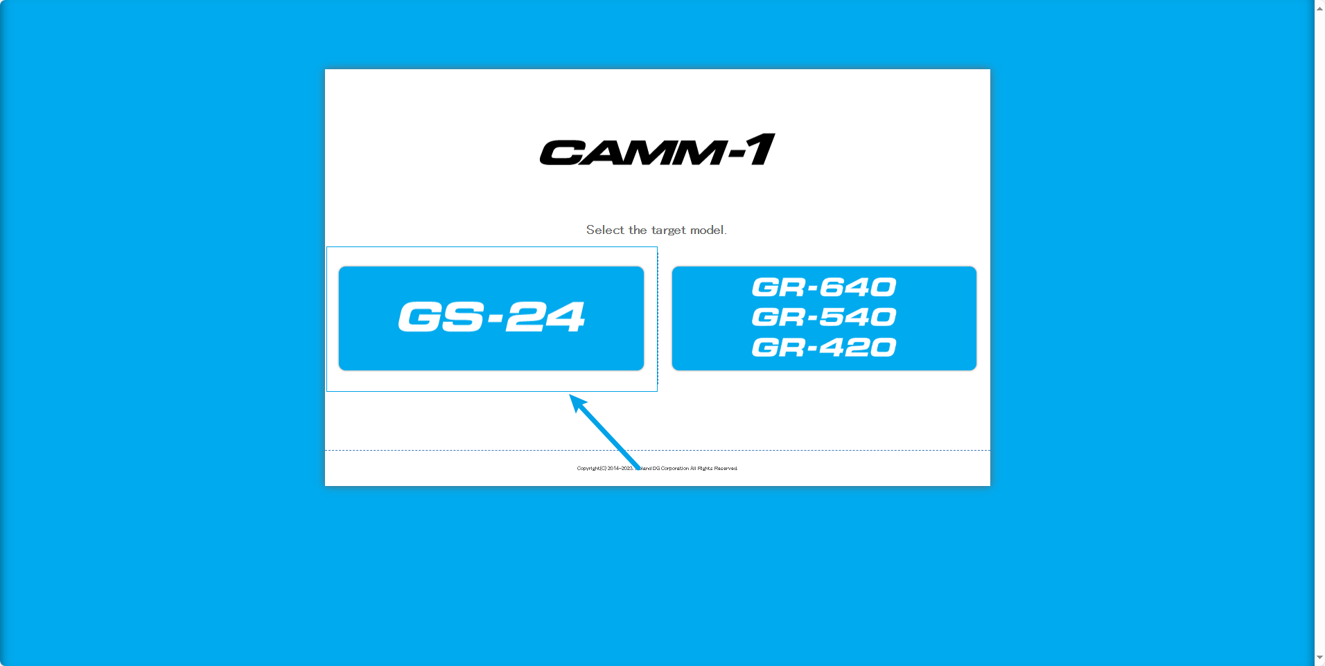
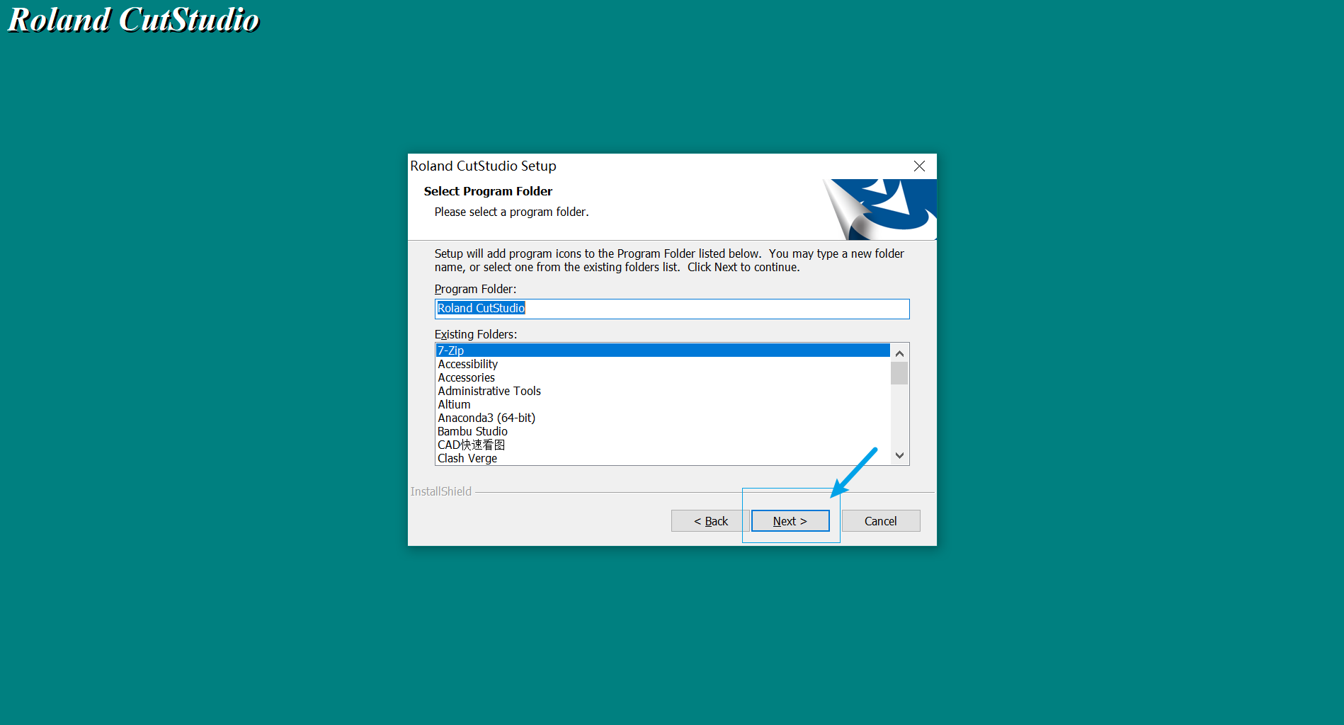
Go to the CutStudio website to download the software, and select the GS-24 version for download.
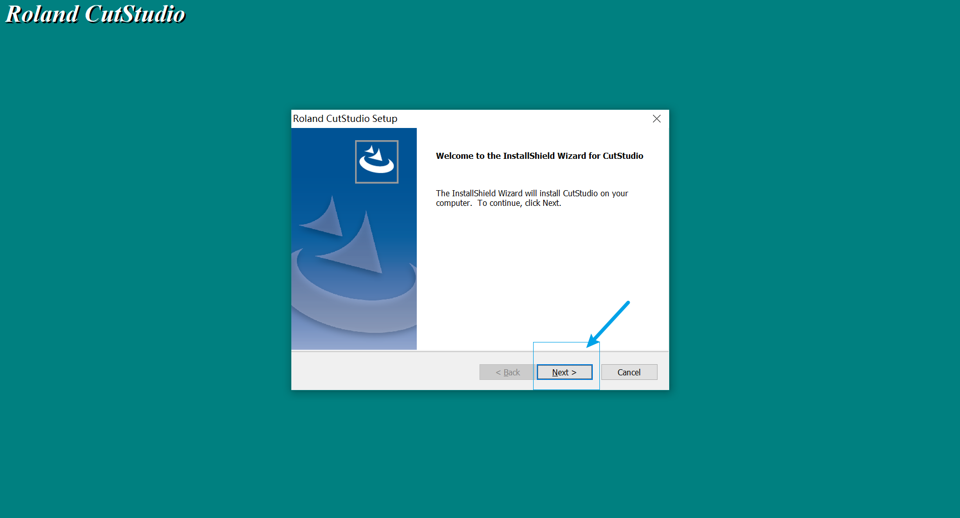
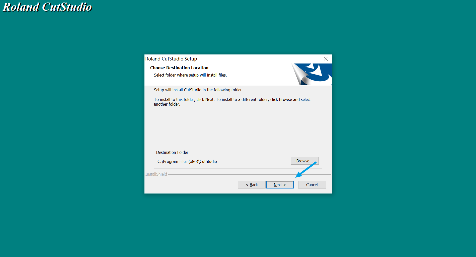
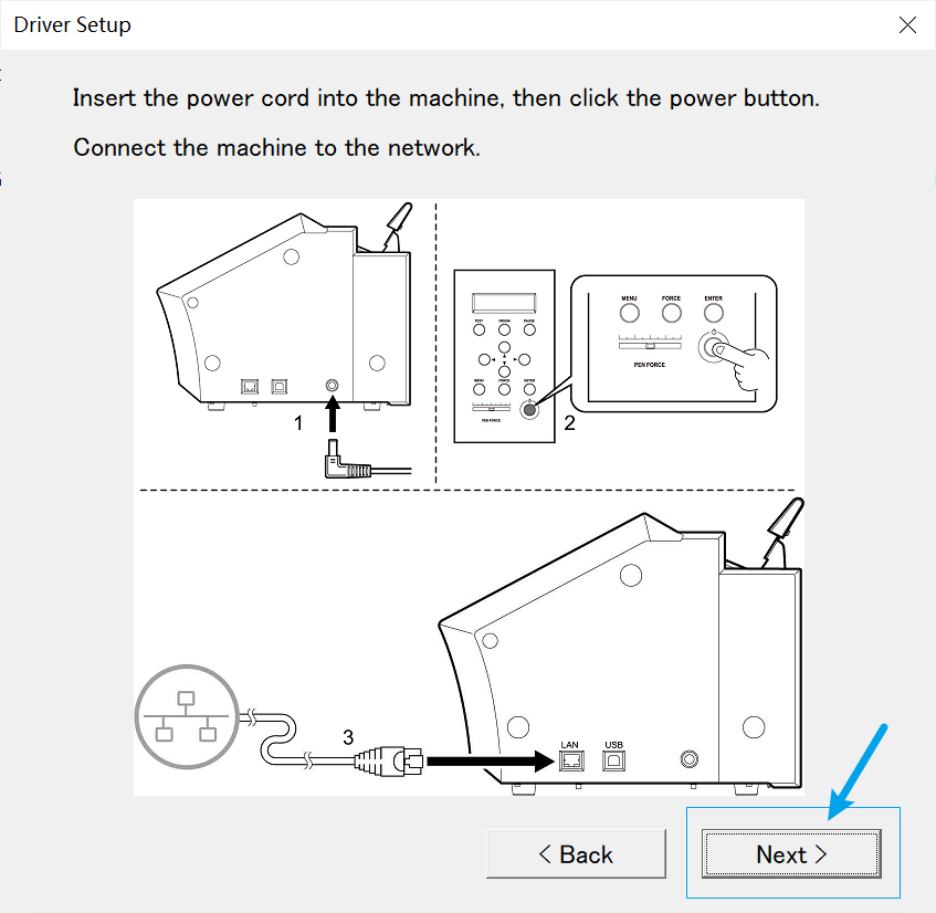
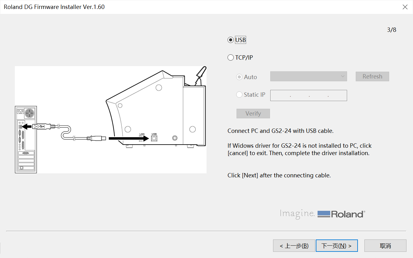
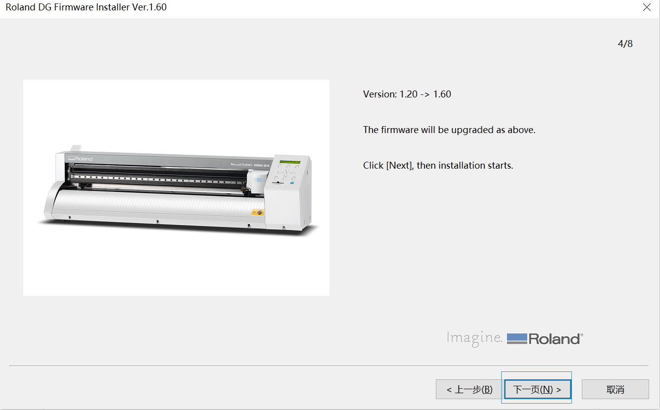
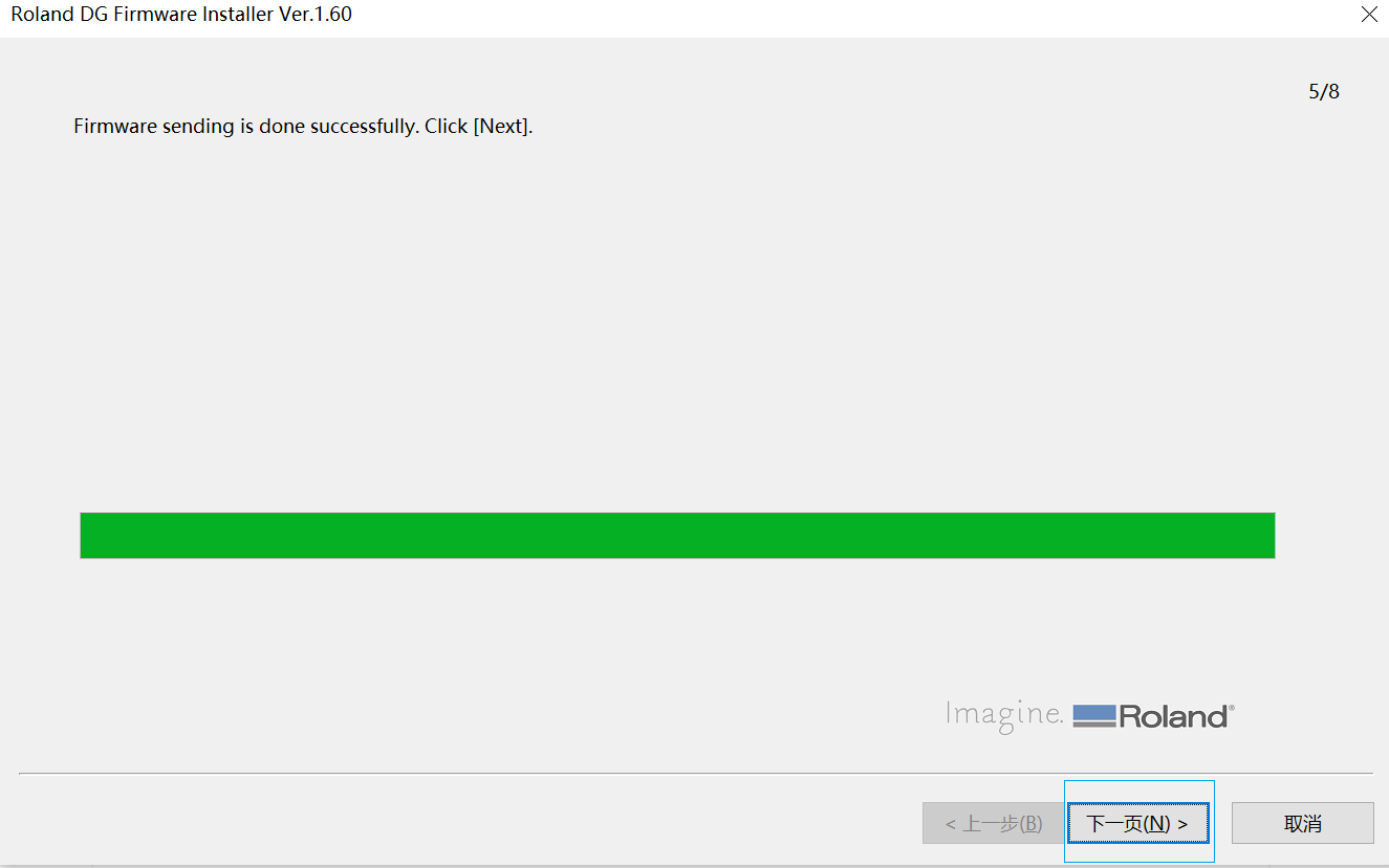
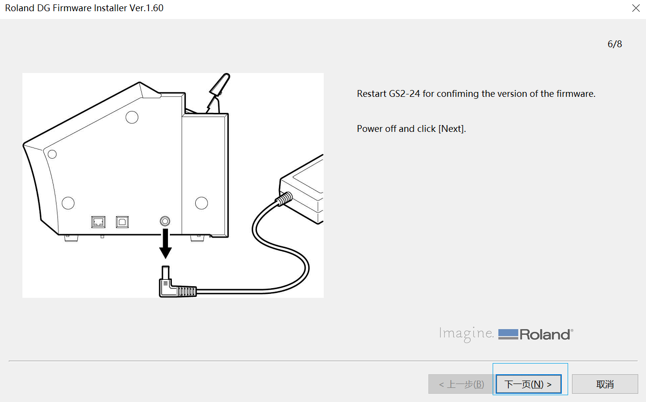
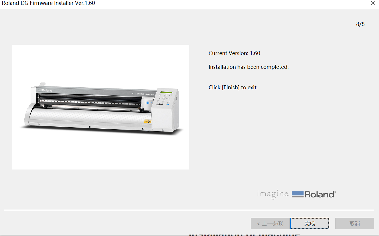
The following is the software installation process: 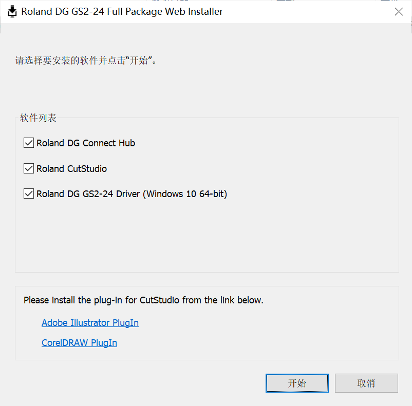
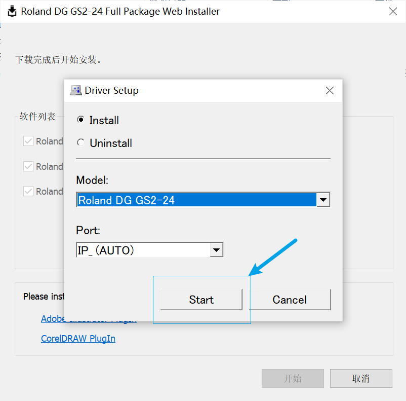

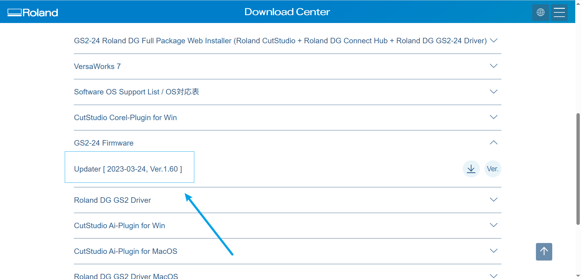
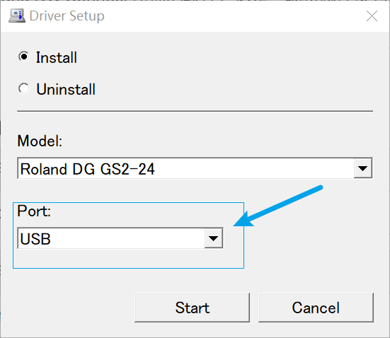
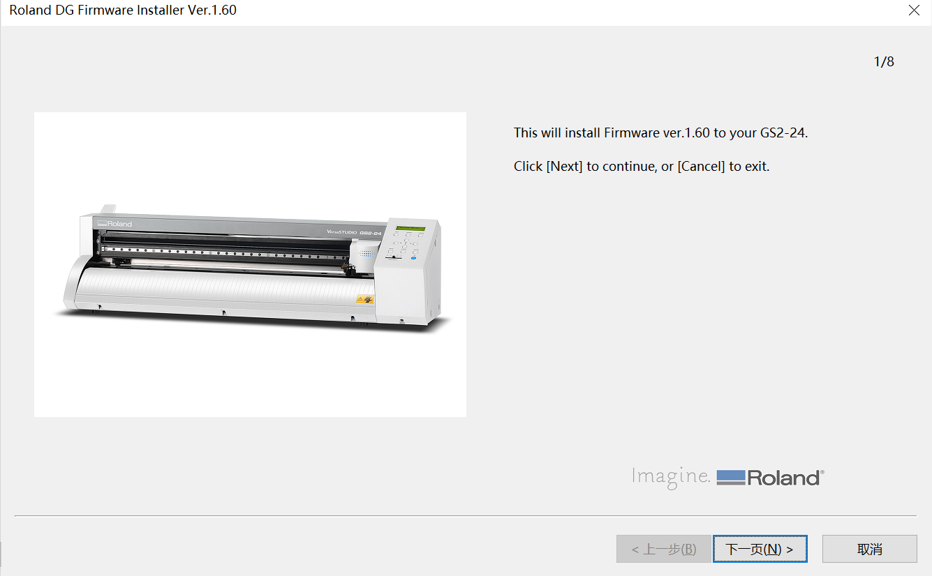
Install the driver:
- Driver download address: https://downloadcenter.rolanddg.com/GS2-24#software
After completing the installation, open the software CutStudio to begin your design and cutting process. 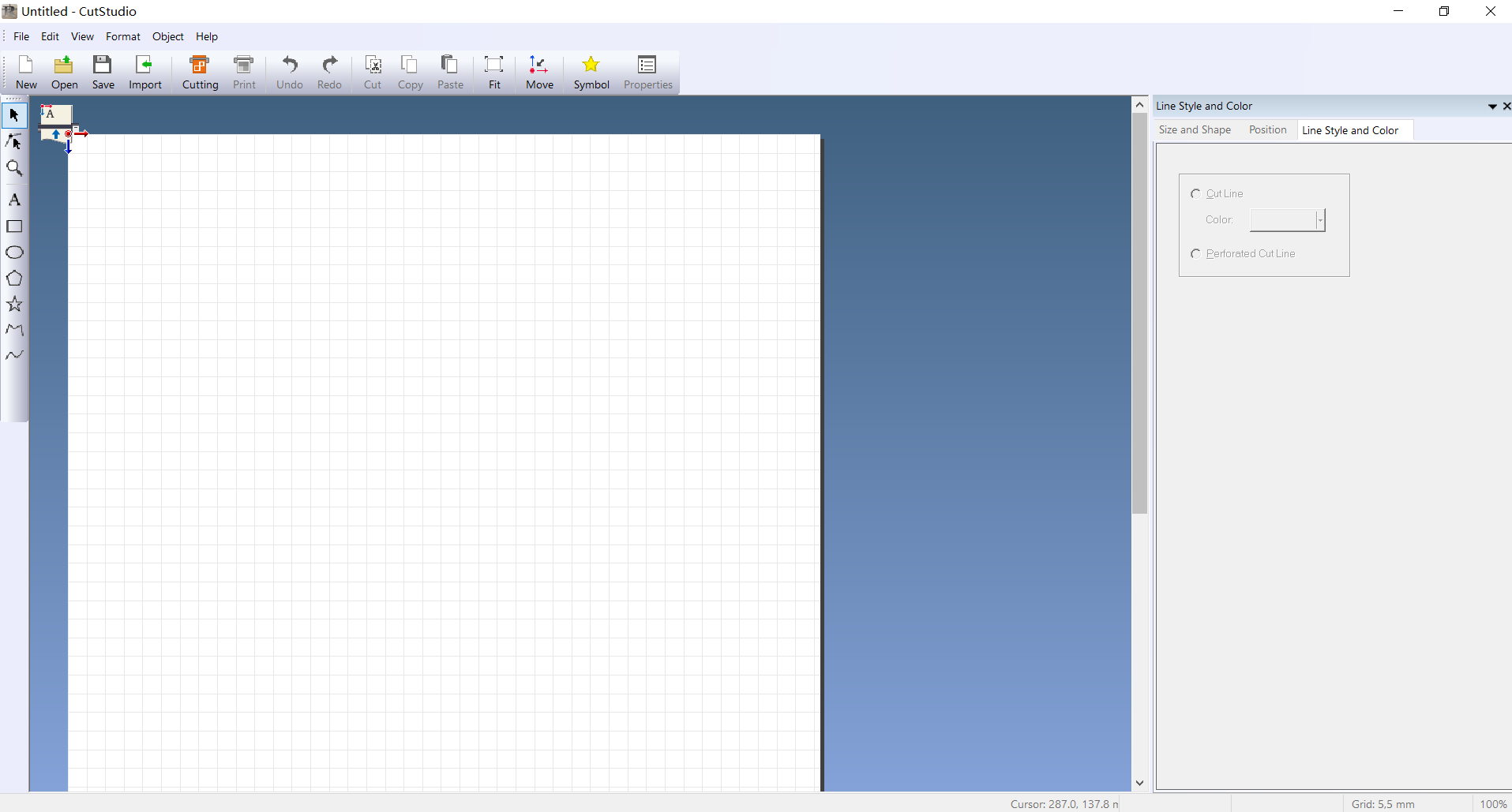
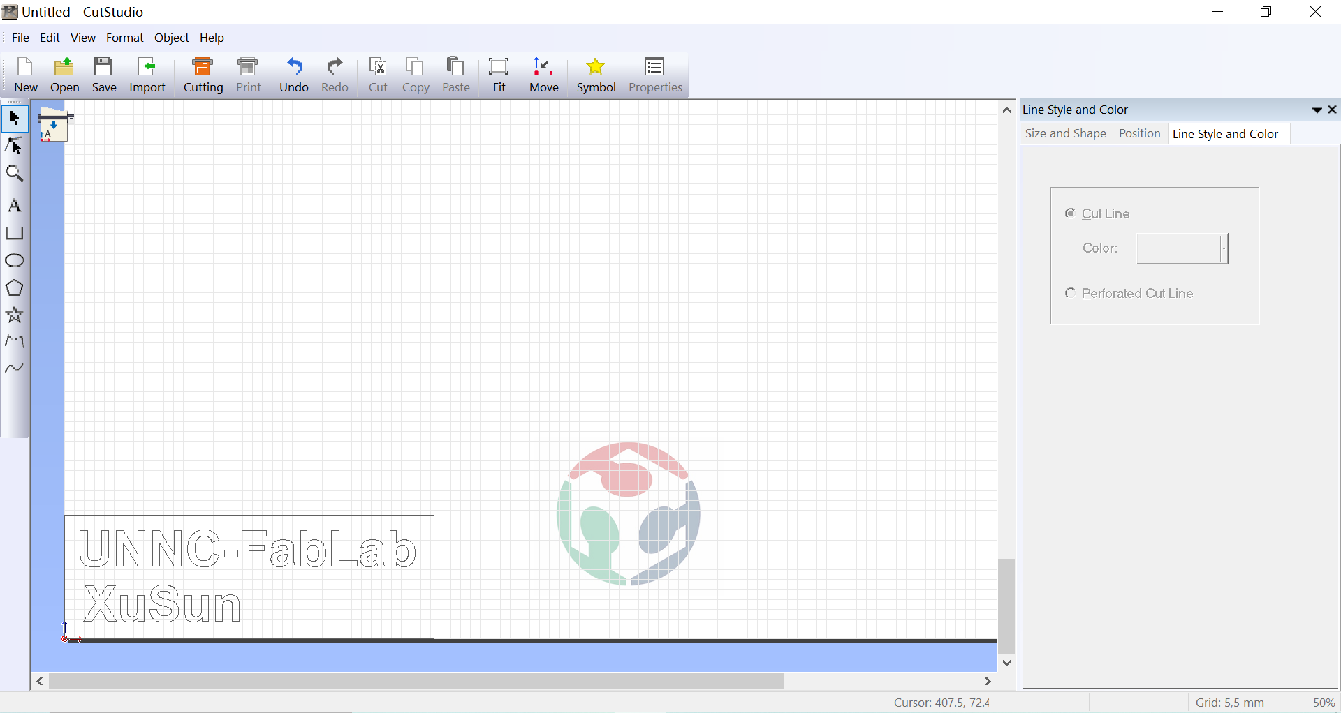
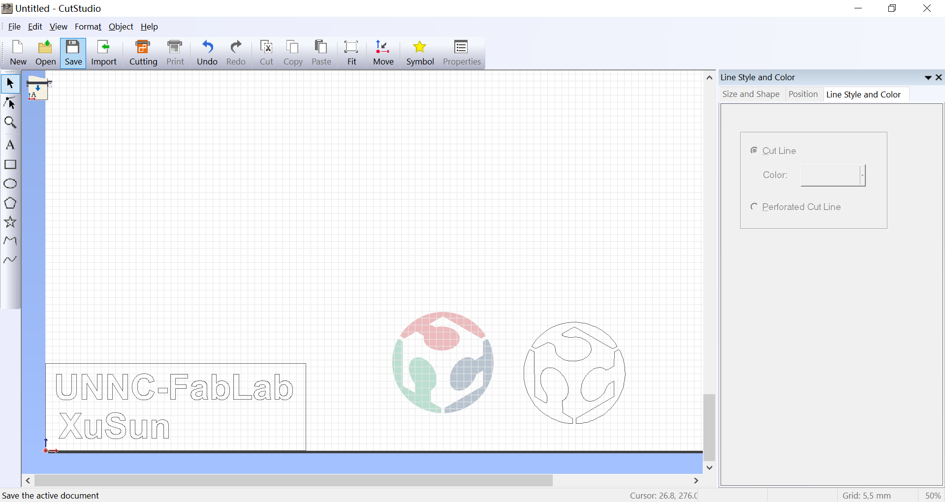
Edit the pattern you want to cut and click the coordinate button to align the coordinates 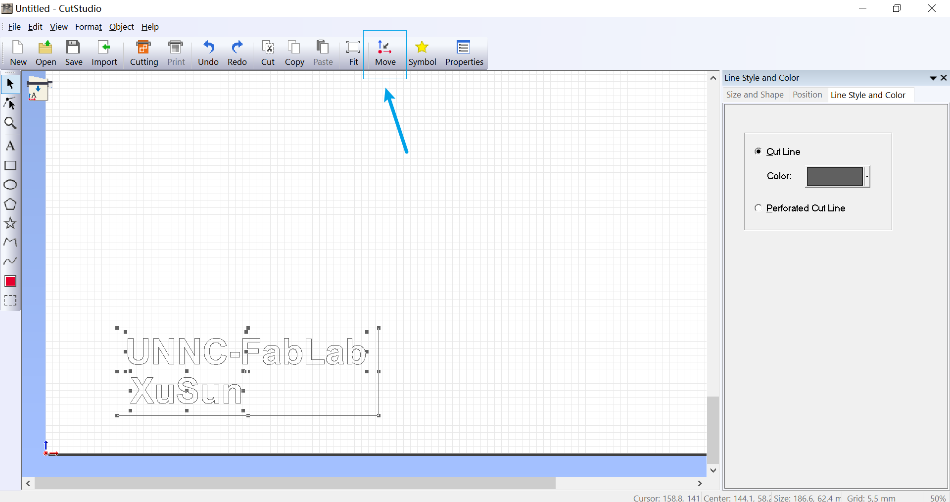
Importing pictures 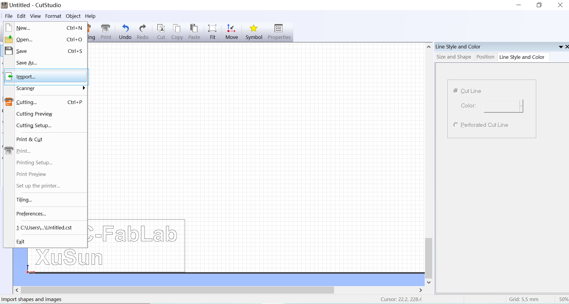
Right click on the image and select Image Outline 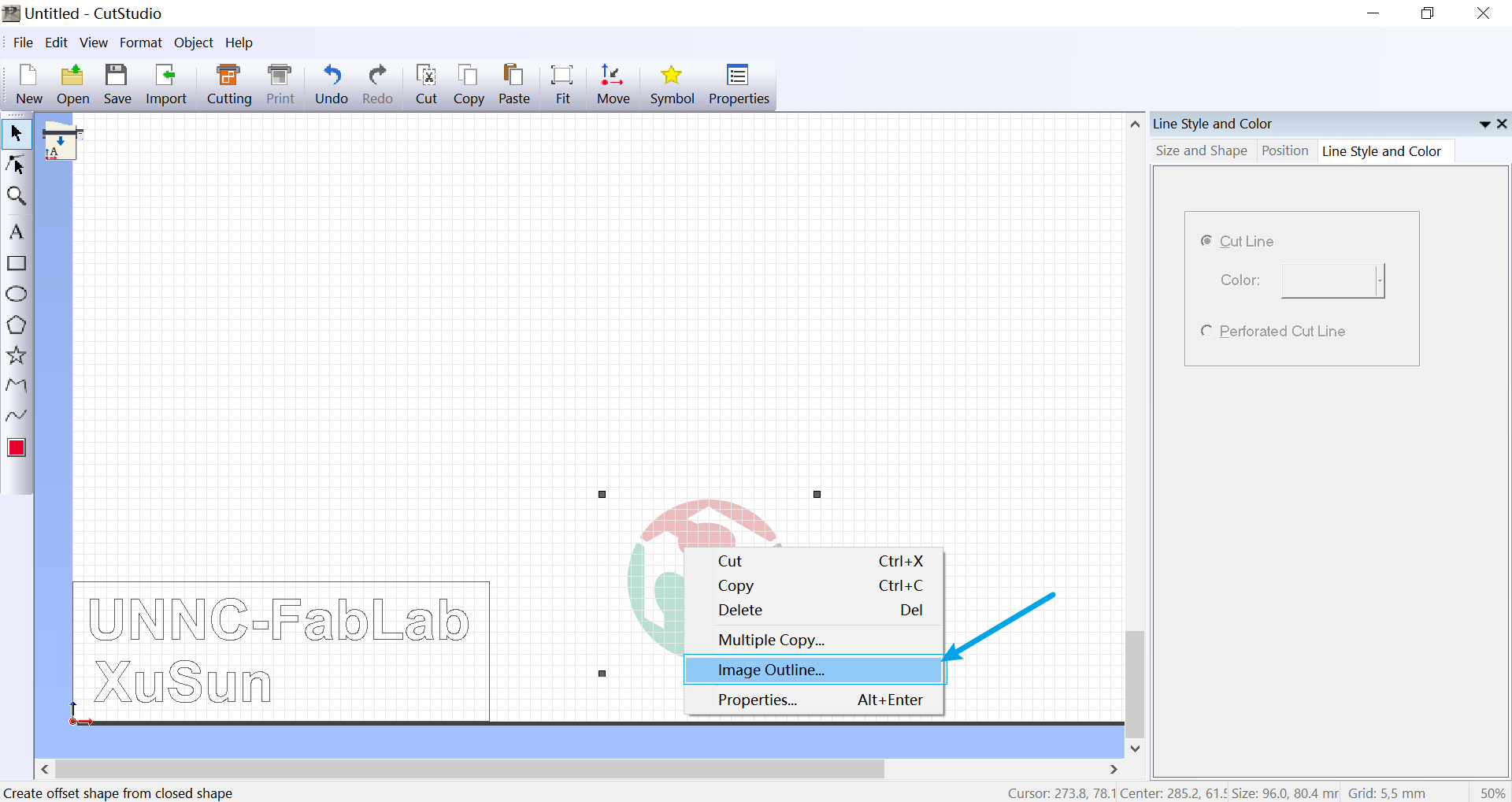
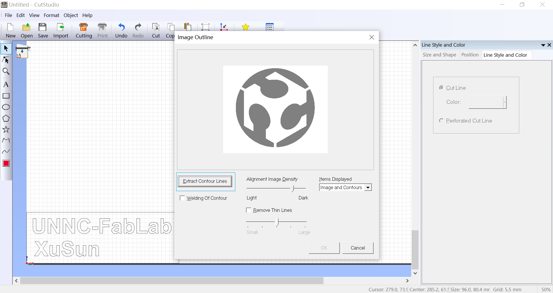
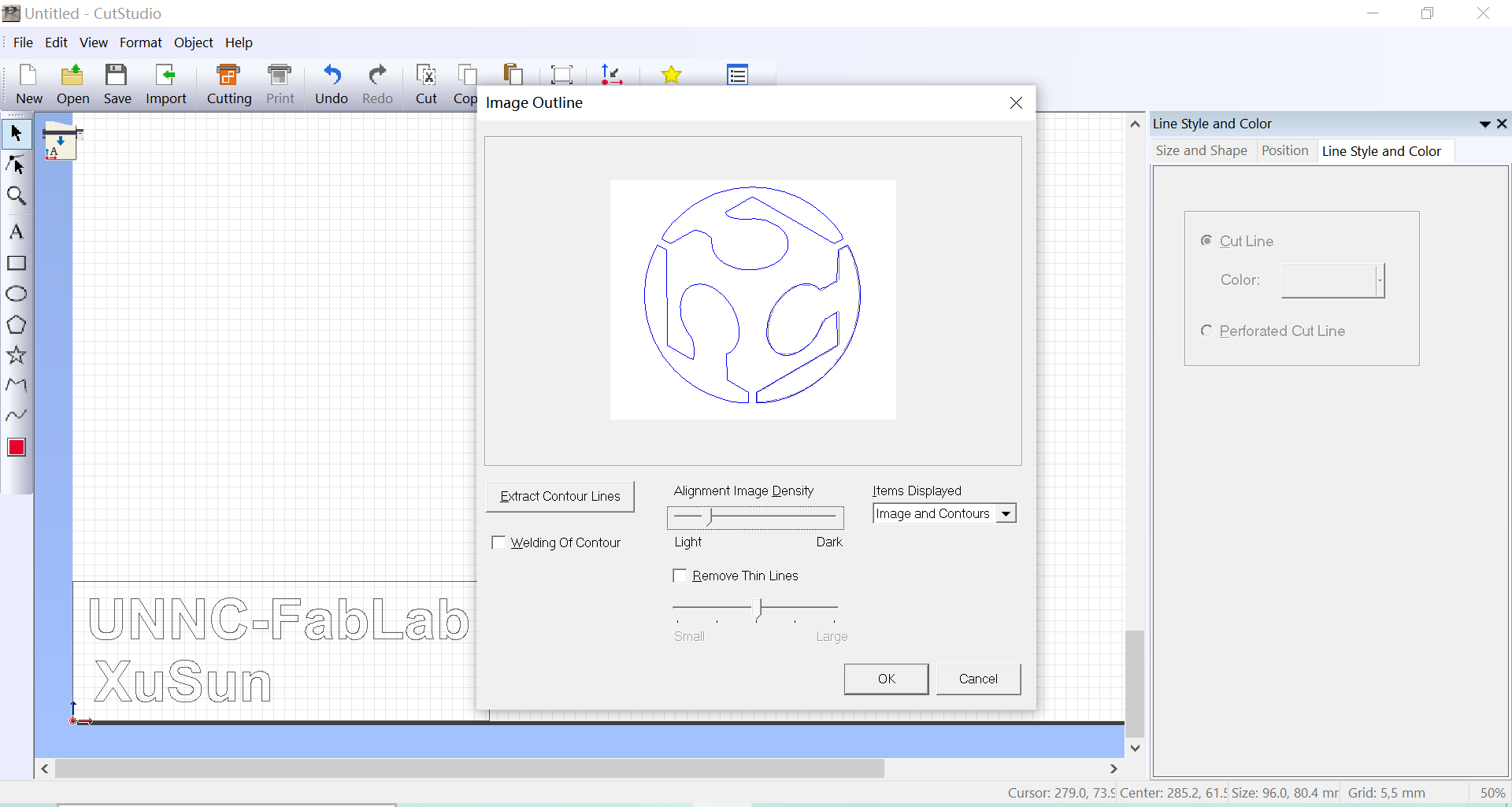
Set the intensity to 120 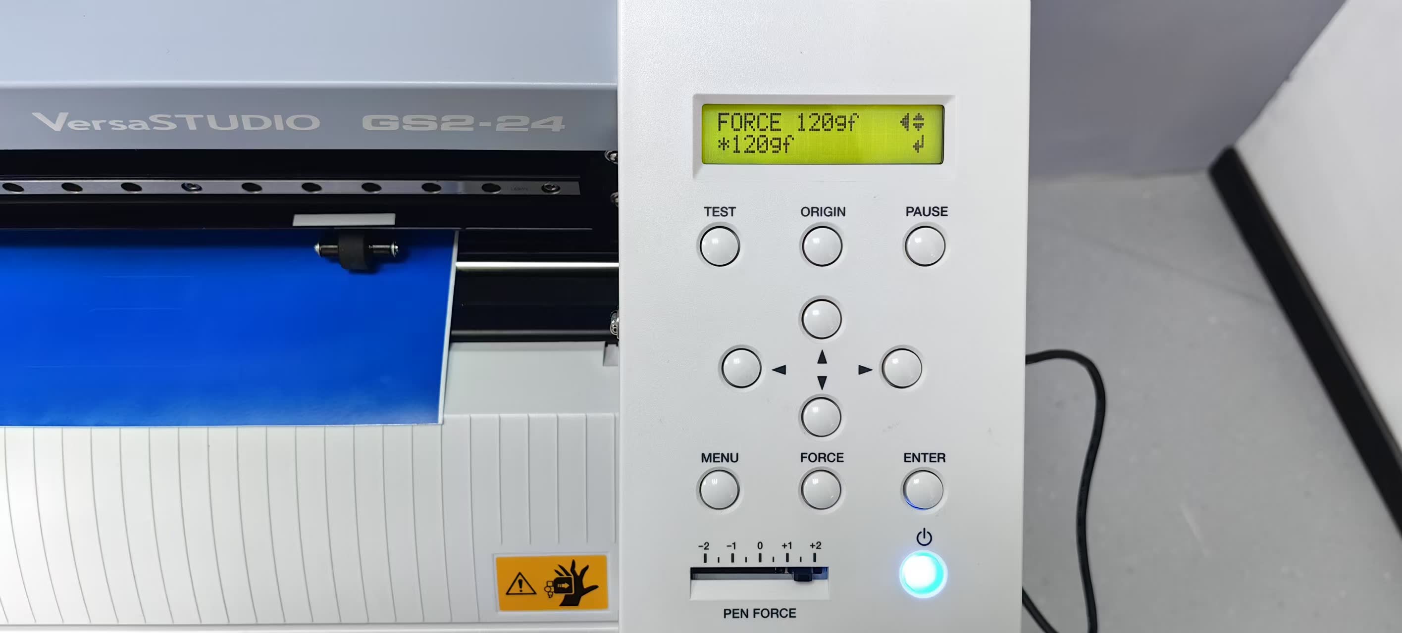
Reference:
The reference and design files are listed below:
The design files of snowflakes in fusion 360 can be found in my repository:https://gitlab.fabcloud.org/academany/fabacademy/2025/labs/unnc/students/xu-sun/-/blob/main/docs/assignments/week3/resource-week3/week3-Snowflakes.f3d?ref_type=heads
The design files for the laser engraver can be found in my repository:https://gitlab.fabcloud.org/academany/fabacademy/2025/labs/unnc/students/xu-sun/-/blob/main/docs/assignments/week3/resource-week3/week3-LASERASSMEBLE.f3d?ref_type=heads
The design files for Vinyl Cutting can be found in my repository:https://gitlab.fabcloud.org/academany/fabacademy/2025/labs/unnc/students/xu-sun/-/blob/main/docs/assignments/week3/resource-week3/week3-VinylCutting.cst?ref_type=heads