Appearance
Week 2 - Computer Aided Design
Assignments
- Model (raster, vector, 2D, 3D, render, animate, simulate, ...) a possible final project
- Compress your images and videos, and post a description with your design files on your class page
Comparison between 3D design tools
Comparison and Interface Display of 3D Modeling Softwaren
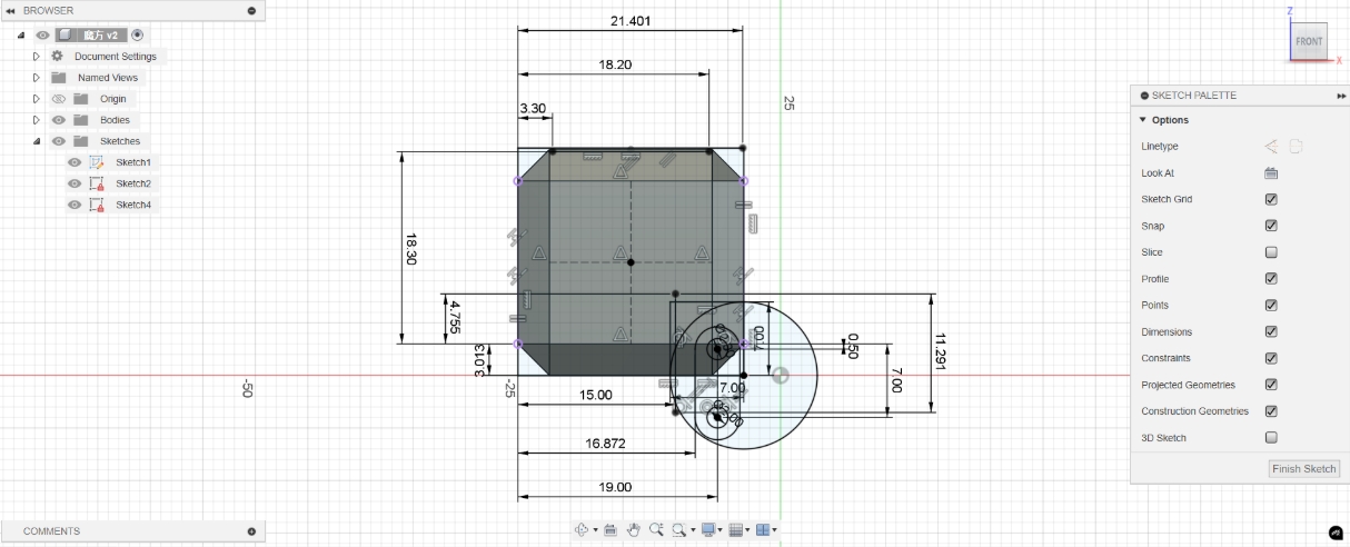
- Fusion 360: A comprehensive tool that combines 3D modeling, mechanical design, simulation, CAM, and CAE. Suitable for manufacturing and product design, it supports cloud collaboration and cross-platform work.The following image is a design of an Infinite Cube I created in Fusion 360 during Week 5.(https://fabacademy.org/2025/labs/unnc/students/xu-sun/assignments/week5/week05.html#infinite-cube)
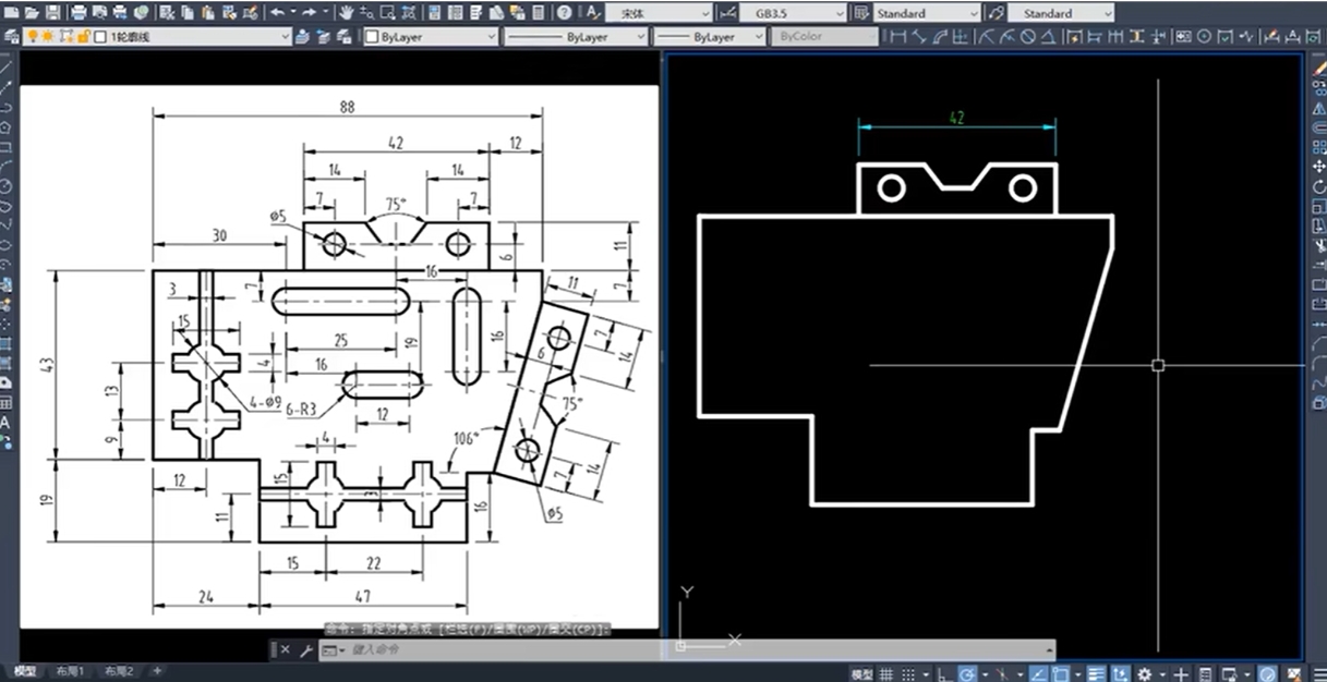
- AutoCAD: Primarily used for 2D drafting and documentation, AutoCAD is ideal for architects and engineers who need highly accurate technical drawings. It offers basic 3D modeling capabilities but isn’t designed for complex surface modeling. The following shows the interface for drawing part diagrams in AutoCAD.
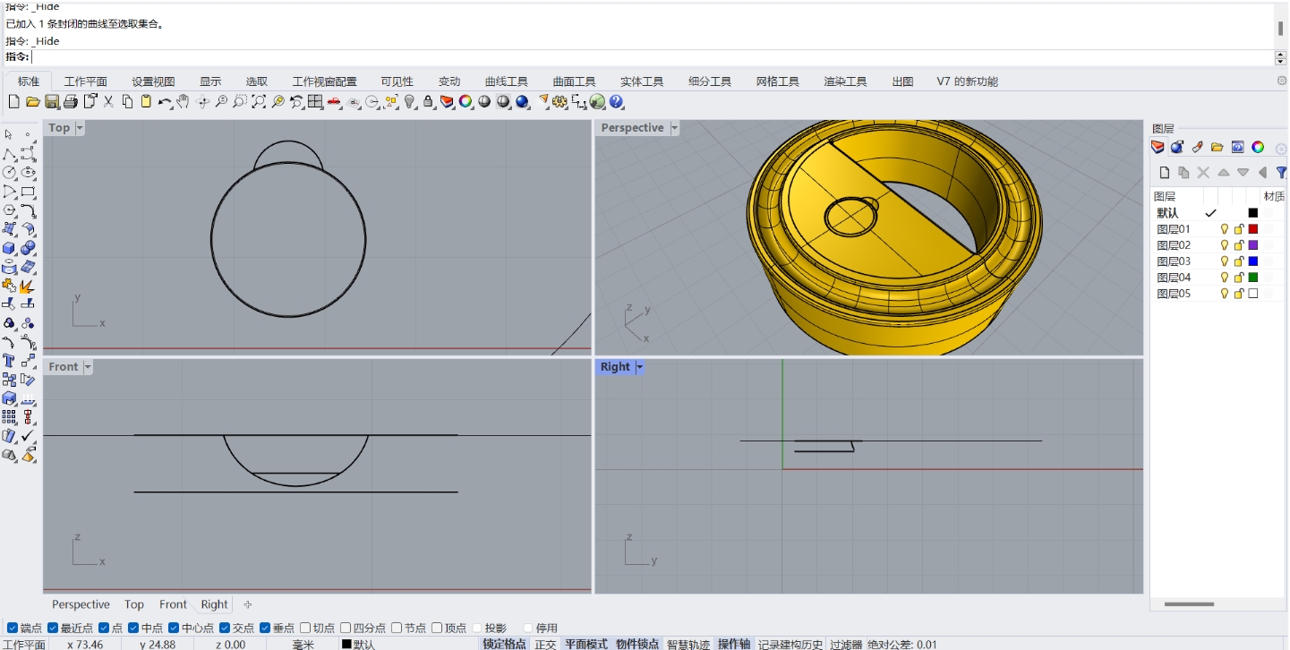
- Rhino: Rhino is ideal for fields such as architecture, industrial design, and jewelry design. When paired with the Grasshopper plugin, it enables parametric modeling. Rhino supports a wide range of file formats and excels at freeform modeling. The following image showcases a simple model of my final project, created efficiently using Rhino.
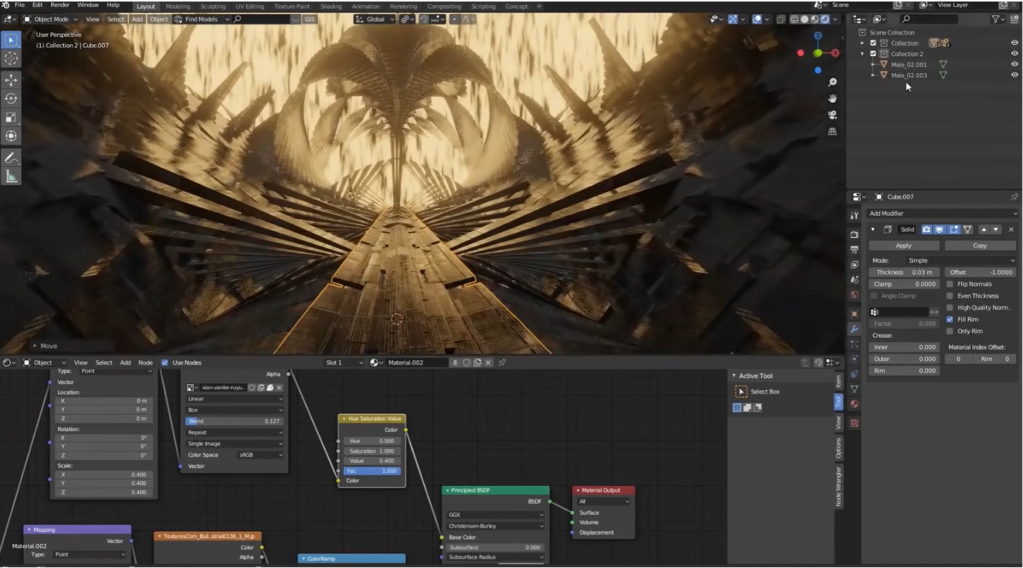
- Blender: Blender is an open-source software designed for creative professionals, supporting 3D modeling, sculpting, rendering, animation, and post-production. Widely used in the film, gaming, and art industries, Blender offers robust functionality, though it comes with a steep learning curve. The following image shows the interface for designing a game scene in Blender.(https://www.bilibili.com/video/BV16Z4y1H7yV/?spm_id_from=333.337.search-card.all.click&vd_source=53c9a555fc18c5cdec4f53fb3b646f09)
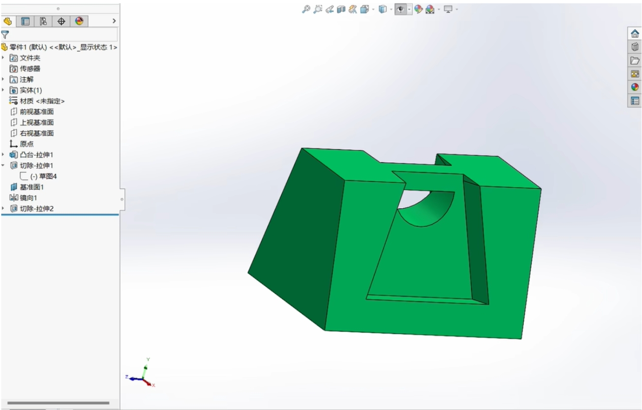
- SolidWorks: SolidWorks is widely used in mechanical design and engineering. SolidWorks excels at parametric modelling of assemblies and parts, including complex surfaces and finite element analysis. It is particularly suitable for industrial product design that demands high precision. The following image shows the interface for designing simple parts using SolidWorks.
| Feature | Fusion 360 | AutoCAD | Rhino | Blender | SolidWorks |
|---|---|---|---|---|---|
| Primary Use | Comprehensive 3D modeling, CAM, CAE | 2D drafting and documentation, basic 3D modeling | Advanced surface modeling, parametric design with Grasshopper | Creative 3D modeling, sculpting, rendering, animation | Precision mechanical design, assemblies, finite element analysis |
| Platform | Windows, Mac, Linux, Web | Windows, Mac, Web | Windows, Mac | Windows, Mac, Linux | Windows |
| Pricing | Subscription-based | Subscription-based | Perpetual license or subscription | Free and open-source | Subscription-based |
| Ease of Use | Moderate to High | Moderate | Moderate to High | Steep learning curve | Moderate to High |
| Collaboration | Extensive | Limited | Moderate | Limited | Extensive |
| Simulation | Advanced | Basic | Basic (via plugins) | Basic (via plugins) | Advanced |
| CAM Capabilities | Advanced | Basic | Limited | None | Advanced |
| 3D Printing Support | Advanced | Basic | Advanced (via plugins) | Advanced | Advanced |
| Electrical Design | Advanced | Basic | None | None | Advanced |
| Community & Support | Extensive | Extensive | Moderate | Extensive | Extensive |
Based on the table comparison, Fusion 360 emerges as the ideal choice for my project. It offers comprehensive 3D modeling capabilities and integrates seamlessly with CAM and CAE tools, making it suitable for a wide range of design tasks. One of its key advantages is the ease of version control, which allows us to easily track design changes and revert to previous versions when needed. Additionally, Fusion 360 supports multiple platforms, including Windows, Mac, Linux, and Web, ensuring flexibility and enabling collaboration across devices. Its streamlined export options also simplify the process of preparing models for 3D printing, which is essential for rapid prototyping and testing. These features make Fusion 360 the most efficient and reliable tool for my project requirements.
2D Modeling
Open Autodesk and create a new file 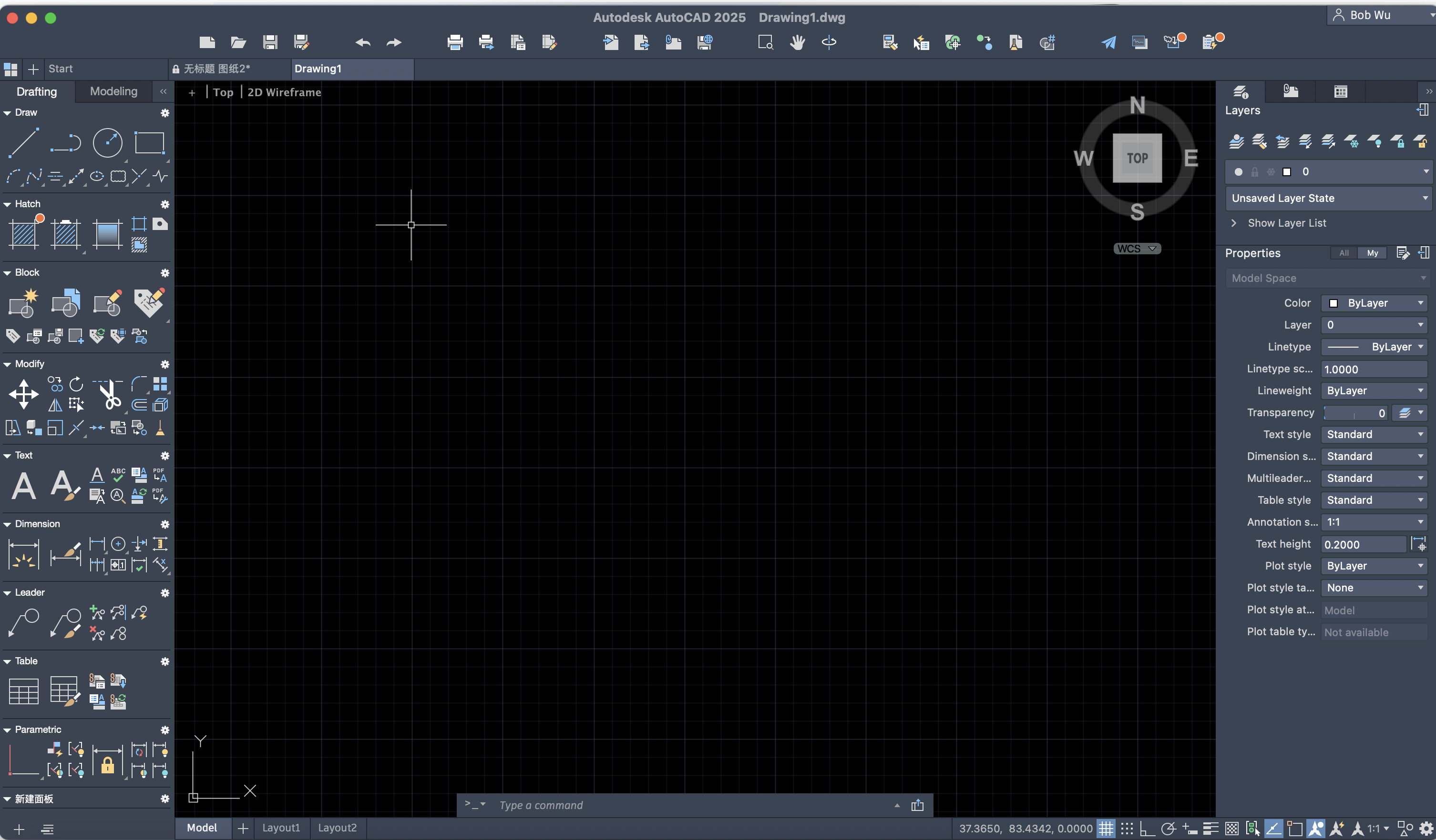
Click on the rectangle tool on the left toolbar 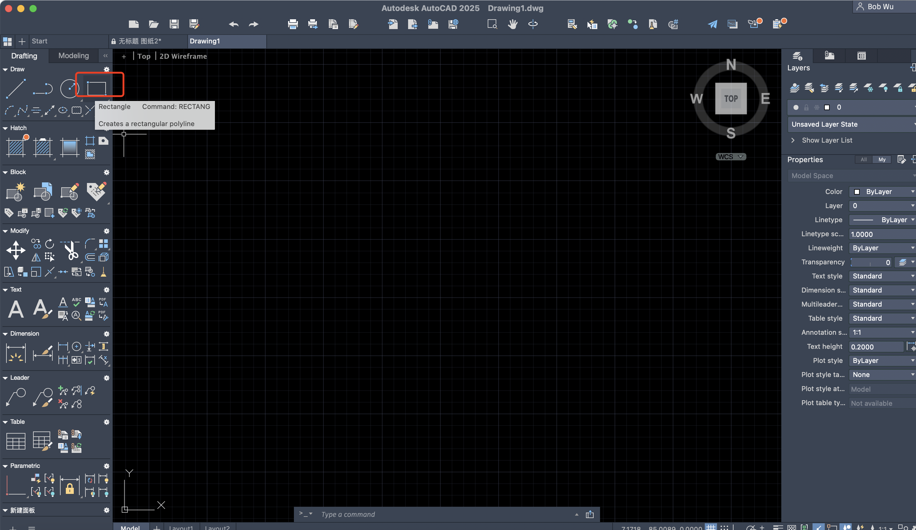
Or type RECTANG in the command line and press Enter 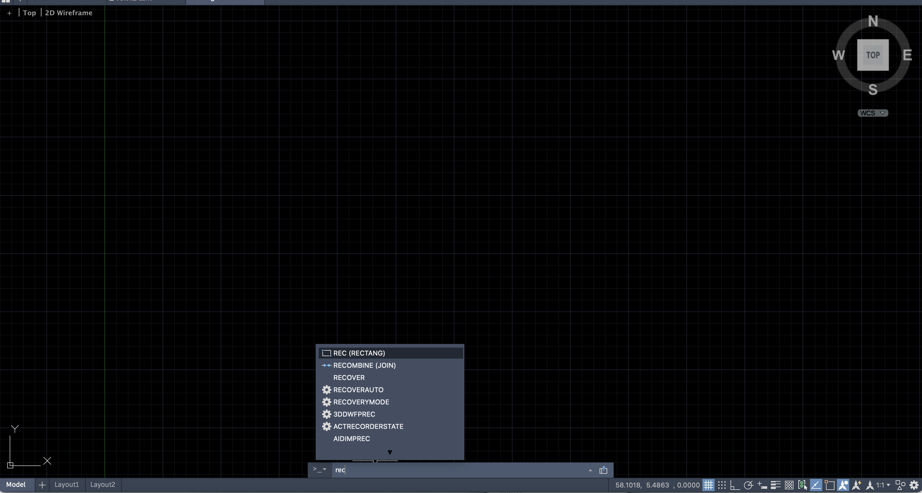
Draw a rectangle and set the width to 30 units 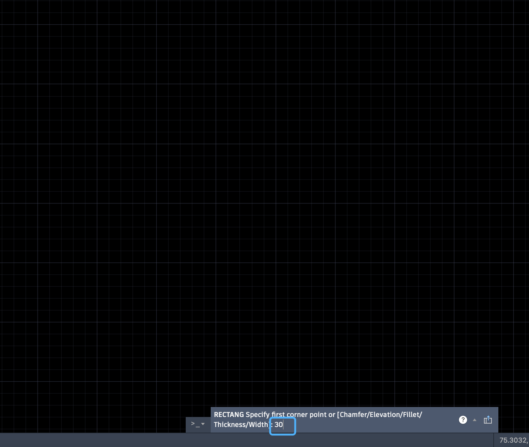
Type OFFSET in the command line and press Enter 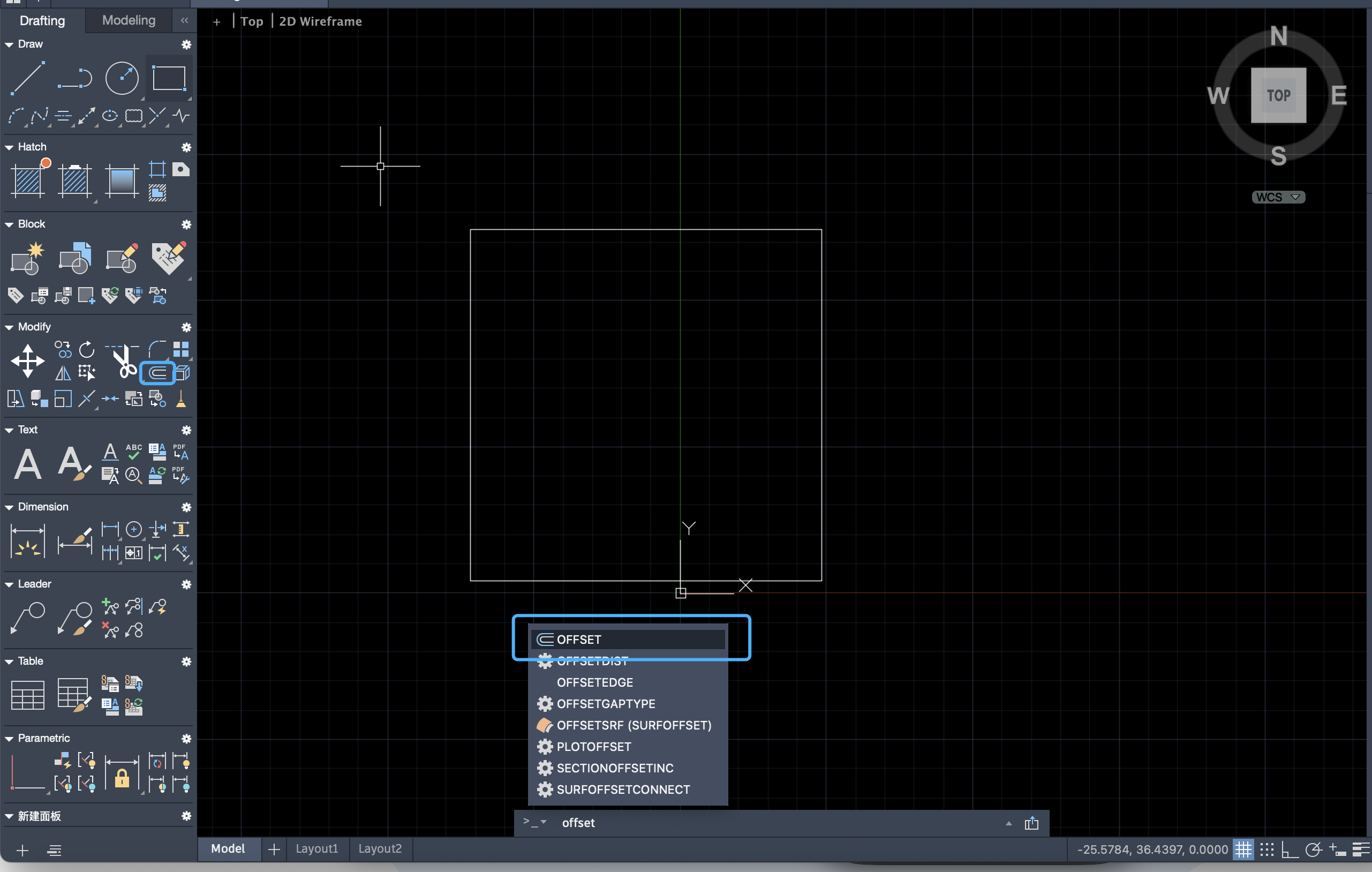
Set the offset distance to 10 units 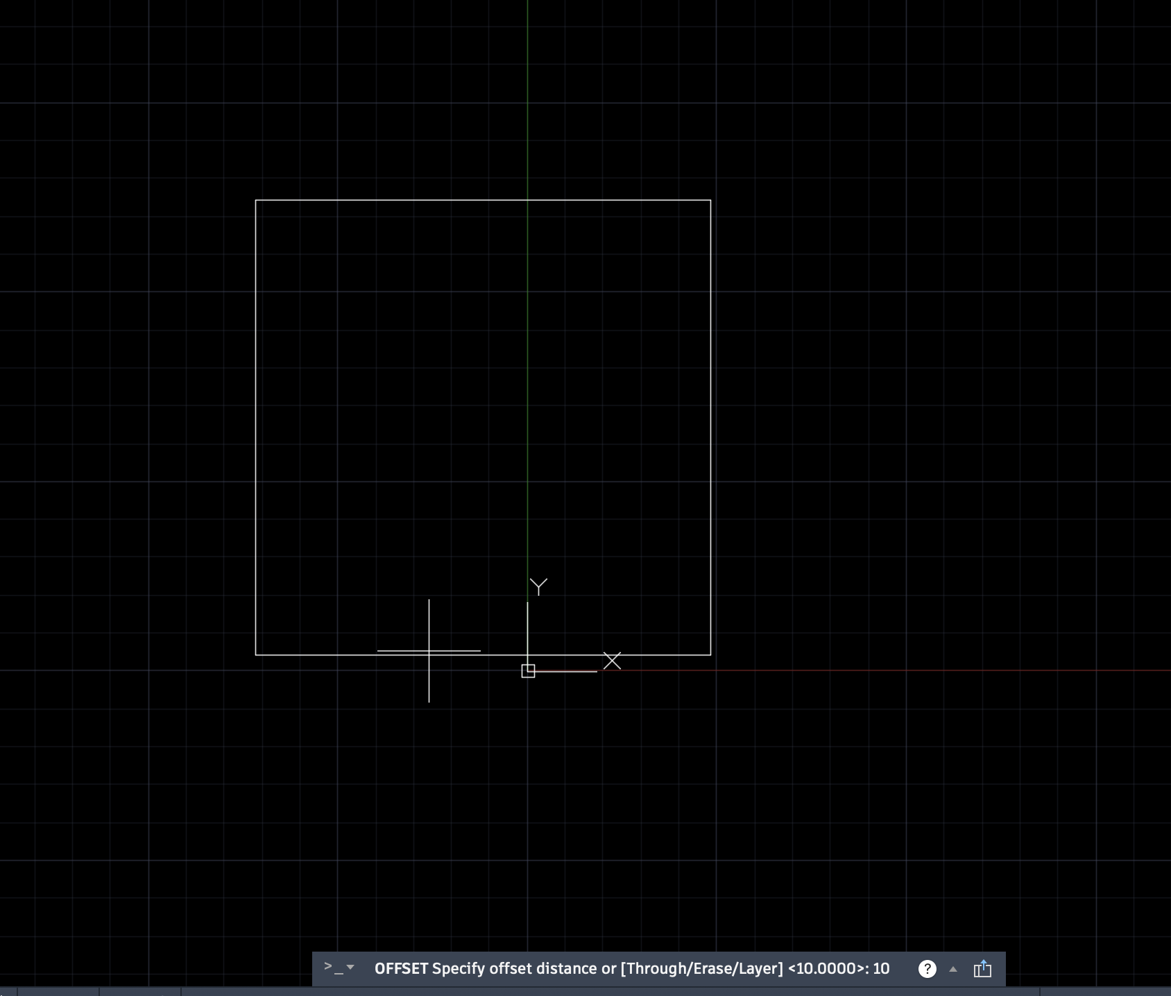
Select the rectangle and apply the offset multiple times 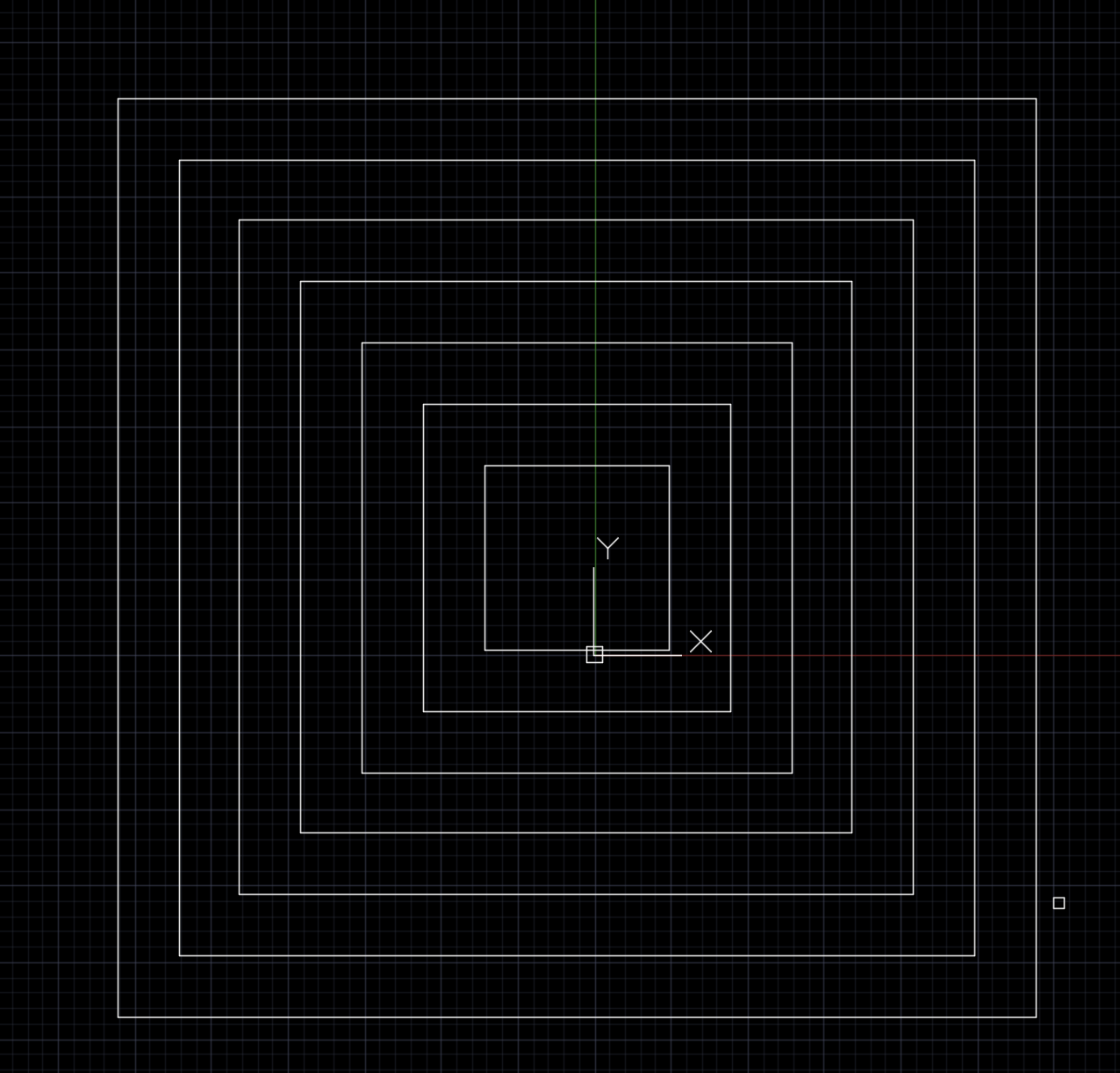
3D Modeling
Fusion 360
Fusion 360 is a cloud-based 3D CAD, CAM and CAE integrated design tool developed by Autodesk. It is widely used in product design, mechanical engineering, manufacturing and maker projects.
It integrates the following core functions:
3D modeling and parametric design: Supports solid modeling, surface modeling, assembly design, and parametric modeling, suitable for precision product development and structural verification.
Engineering Simulation (CAE): It can perform various types of engineering simulations, including finite element analysis (FEA), motion simulation, and stress analysis.
CNC Programming (CAM): It supports 2.5D to 5-axis machining path generation, making it suitable for CNC machining and manufacturing.
Electronic Design (ECAD): Built-in circuit design tools to create circuit diagrams and PCB layouts.
Rendering and Animation: Generate high-quality product renderings and demonstration animations.
Cloud collaboration and version control: Projects are saved in the cloud to facilitate multi-person collaboration and historical version management.
Fusion 360, with its powerful feature set and intuitive user interface, is widely used in education, makerspaces, and small studios. In the upcoming Fab Academy assignments, I will use Fusion 360 as my primary design tool to complete various modeling and fabrication tasks.
My current final assignment idea is to detect the driver's fatigue during driving and determine whether the autonomous driving system needs to take over vehicle control. The system will assess the driver's fatigue level by other physiological signals, thereby improving driving safety.
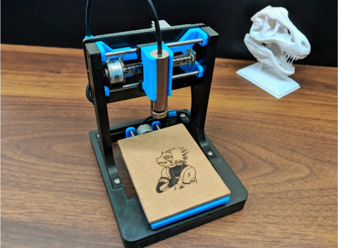
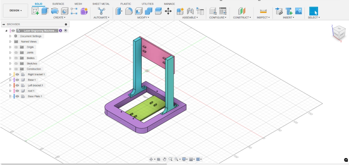
Inspired by the V-One PCB printer, I plan to build a device based on similar 3D printing technology to make the PCB circuit boards required for this project. The structure of this device is similar to a micro laser engraving machine, but the laser head is replaced by a syringe filled with conductive silver paste. By controlling the syringe to extrude the silver paste, conductive lines can be directly drawn on the surface of the substrate to achieve rapid prototyping of the circuit board. This week's homework is designed based on the micro laser engraving machine as a prototype, and it also serves as an introductory exercise for me to learn Fusion 360.
The referenced micro laser engraving machine effect diagram is as follows. This project is an open source solution from the Instructables website:DIY Mini CNC Laser Engraver
 We can visit the Fusion 360 official website to download the software. Before using it, We need to register for an Autodesk account. Once the installation is complete, we can start modeling with Fusion 360, including tasks such as creating sketches, generating 3D models, and assembling components.
Create Sketch
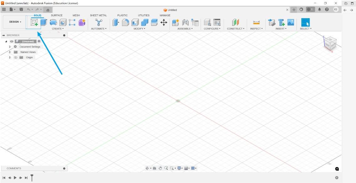
After entering Fusion 360, click the Create Sketch button in the upper left corner to start sketching.
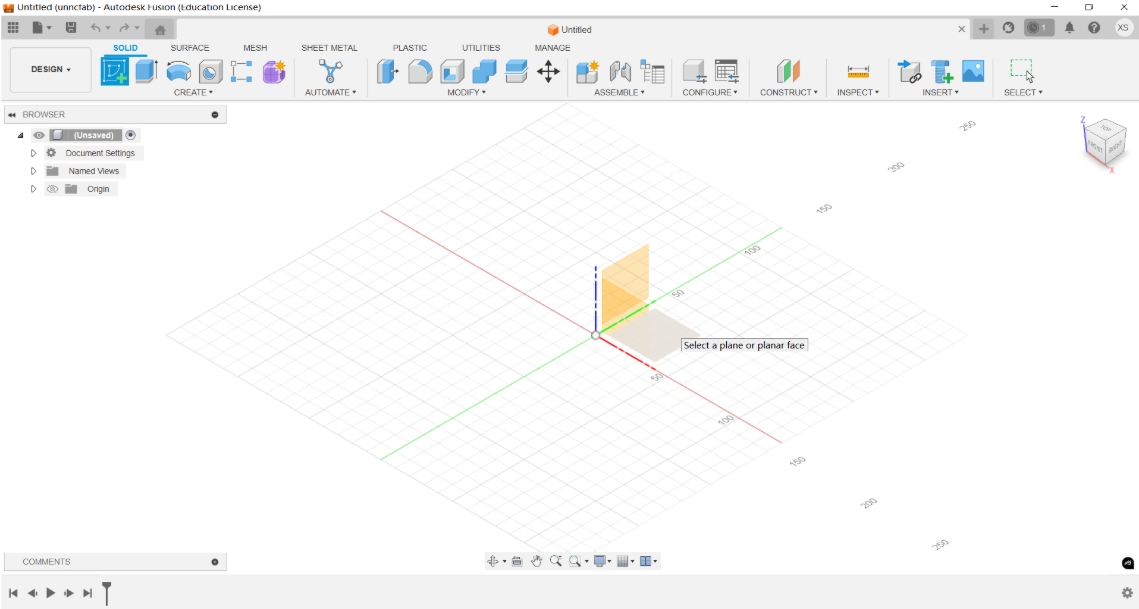
 Next, you need to select a drawing plane. Typically, you can choose the front view, left view, or top view as the reference plane, depending on the orientation and perspective most suitable for your design.
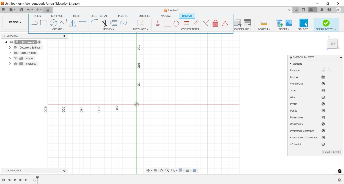
 In sketch mode, you can use the upper toolbar to perform the following operations:
Sketch Creation Tool:
- Used to draw basic geometric shapes, including: Line, Circle, Rectangle, Arc, and Polygon, which form the foundation of the sketch.
Sketch Editing Tools:
Used to modify and adjust existing geometry, such as:
Trim: Removes unnecessary parts of a sketch
Offset: Creates a contour at an equal distance from the selected geometry
Mirror: Duplicates geometry symmetrically across a selected line
Geometric Constraint Tools:
- Used to define relationships between sketch elements, making the sketch more stable and controllable. Common constraints include: Coincident, Parallel, Perpendicular, Equal, and Horizontal/Vertical
Fixing and Positioning Tools:
- Fix/UnFix: Locks or unlocks geometry in place to prevent unintentional movement
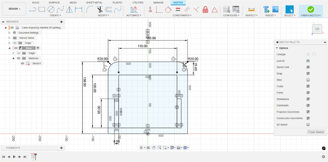
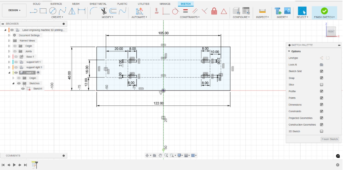
 After creating a rectangle, we can use constraint tools to precisely define its dimensions and position. Then, apply the Fillet tool to round the corners of the rectangle, and use the Trim tool to remove any unnecessary lines, making the sketch cleaner and more refined.
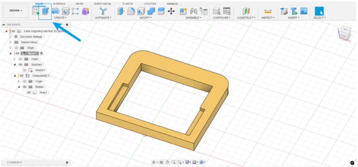
Create Feature
After finishing the sketch, click the Finish Sketch button to exit the sketch mode. Next, use the Extrude function to extrude the selected sketch outline to generate a 3D solid model. You can set the height, direction, and whether it is a solid or cutting operation.
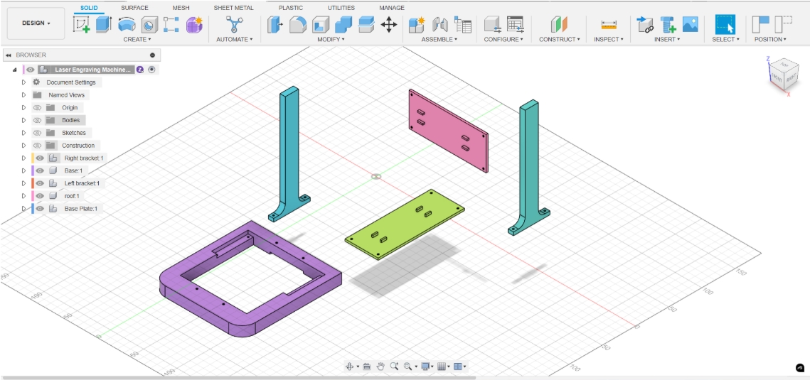
 The following is the modeling process of other parts. For parts with the same or identical structure, we can quickly create multiple copies by copying and pasting to improve modeling efficiency.
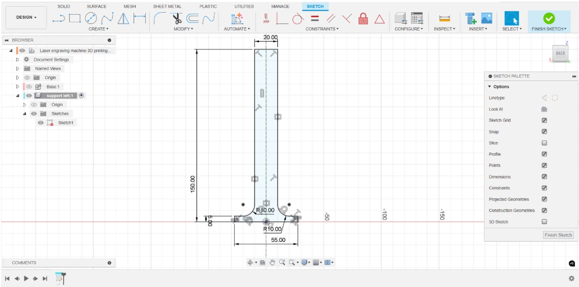
Create Sketch
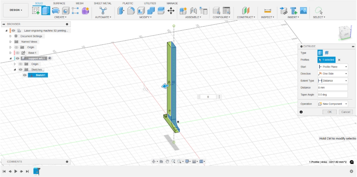
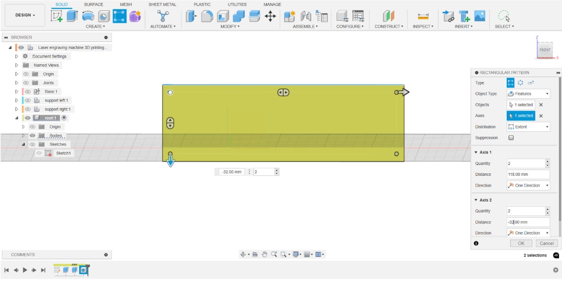
 Stretch Operation
 Hole
Hole
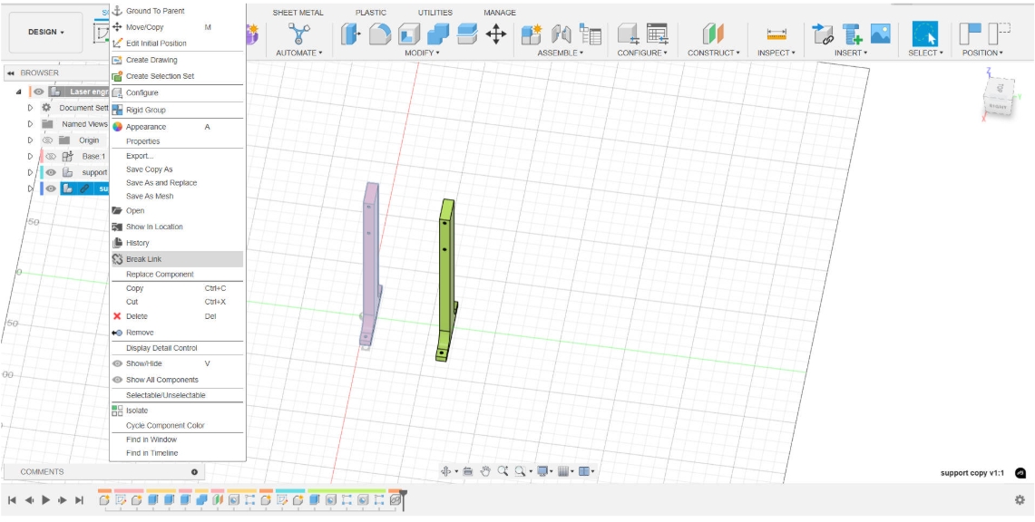
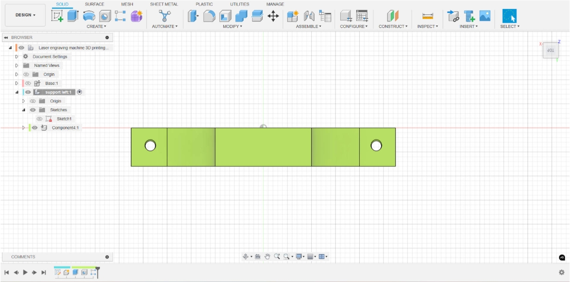 Copy and Paste
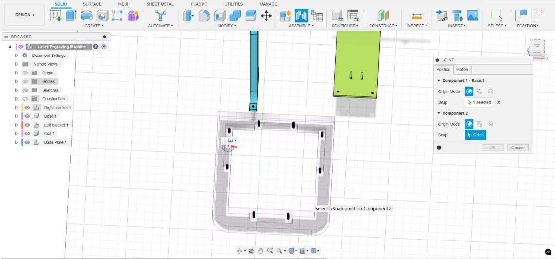
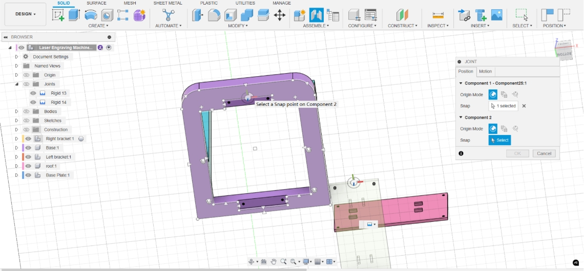
Joint
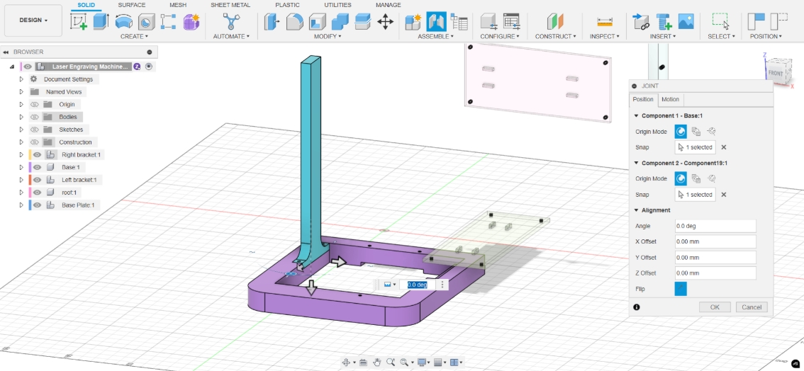
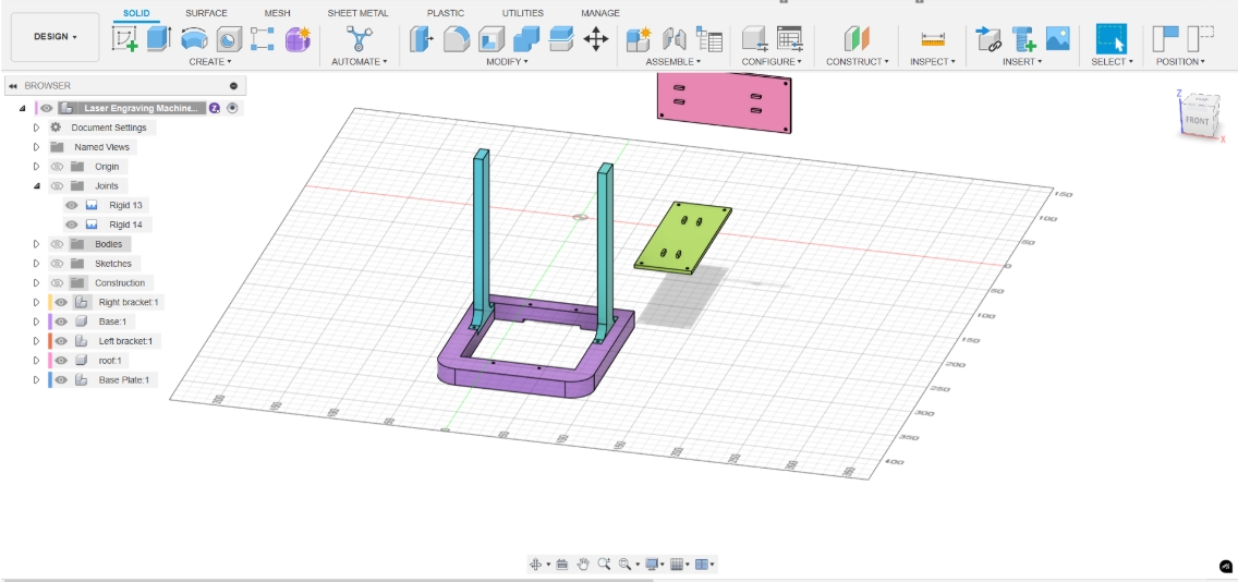
Next, use the Joint function to assemble the parts. Click the Joint tool under Assemble, then select the points or faces on the two parts that need to be aligned. The system will automatically align them. We can also adjust the assembly angle, direction, or degrees of freedom as needed to achieve the desired assembly effect.
The Joint function supports various assembly types, including Rigid, Revolute, Slider, Cylindrical, and Ball joints. By selecting alignment points or faces and setting the degrees of freedom and angle limits, we can precisely control the relative motion between parts, thus building an assembly model with realistic mechanical behavior.

Compression tools
I will use FFmpeg to compress images and videos.
Next, I will introduce the installation and use of ffpmeg
ffmpeg download
Go to the ffpmeg official website to download
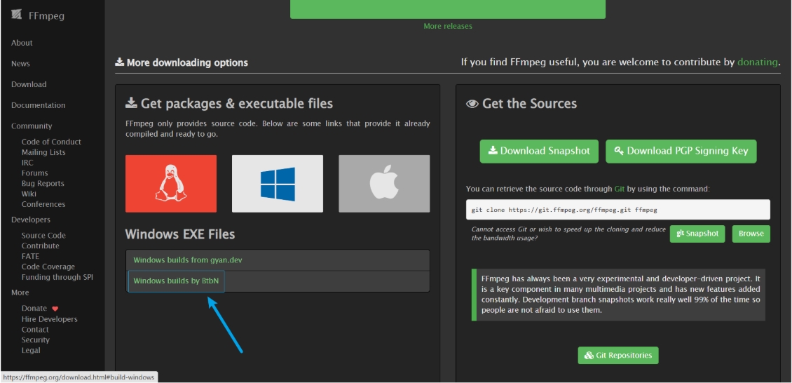
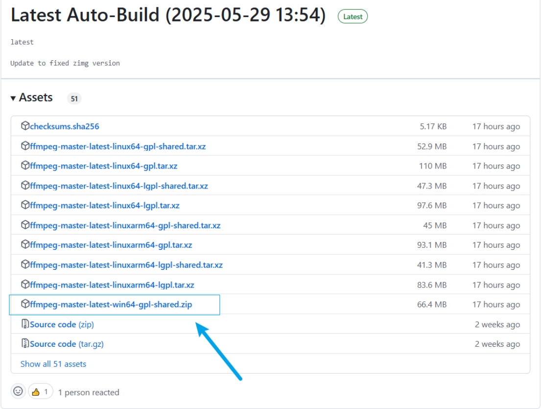 After downloading and unzipping, there are three executable files in the bin directory. The ffpmeg.exe file is the file we will use later. If you want to call the command globally, you also need to add the bin folder directory to the environment variable
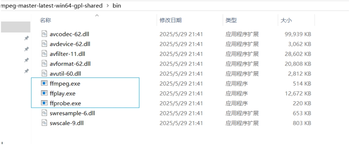
Image compression
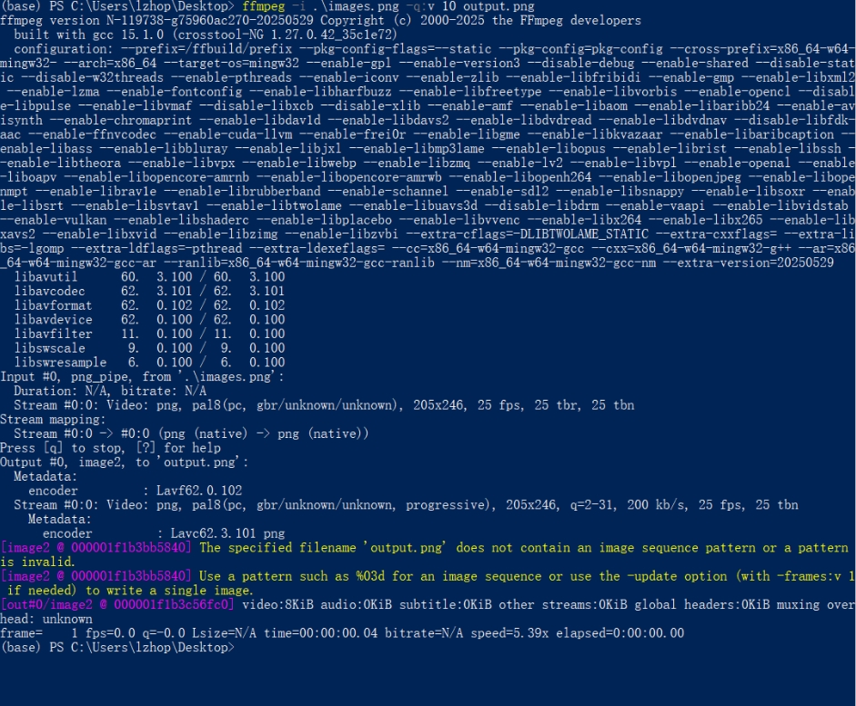
Use the following command to compress the image. compress_level is a positive integer representing the compression level. The larger the value, the higher the compression level.
bash
ffmpeg -i image_source -q compress_level out_sourceTo test the effect, I downloaded an image from the open source library Pexels.
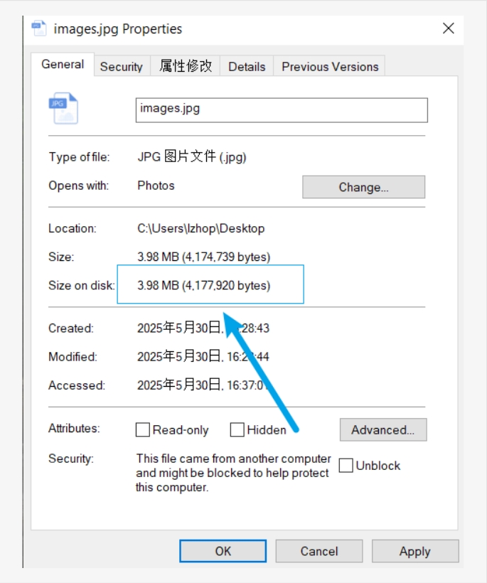
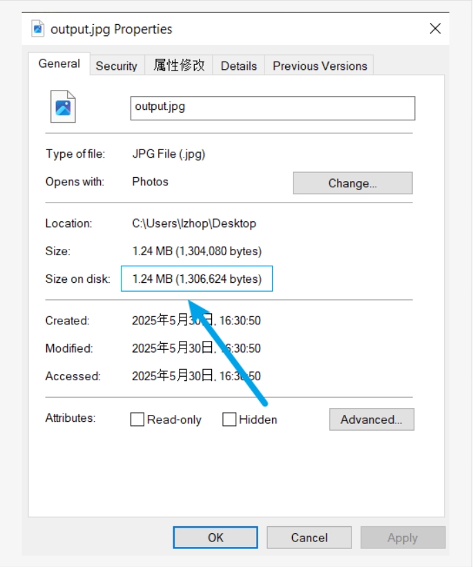
 Comparison of the original image and the compressed image, the left one is the original image:
 |  |
|---|
Compressed from 3.98MB to 1.24MB, a compression of about 68.84%.
 |  |
|---|
Video Compression
Video material found on this open source website: https://mixkit.co/free-stock-video/dog-resting-with-a-sweet-look-101217/
Use the following command to compress:
bash
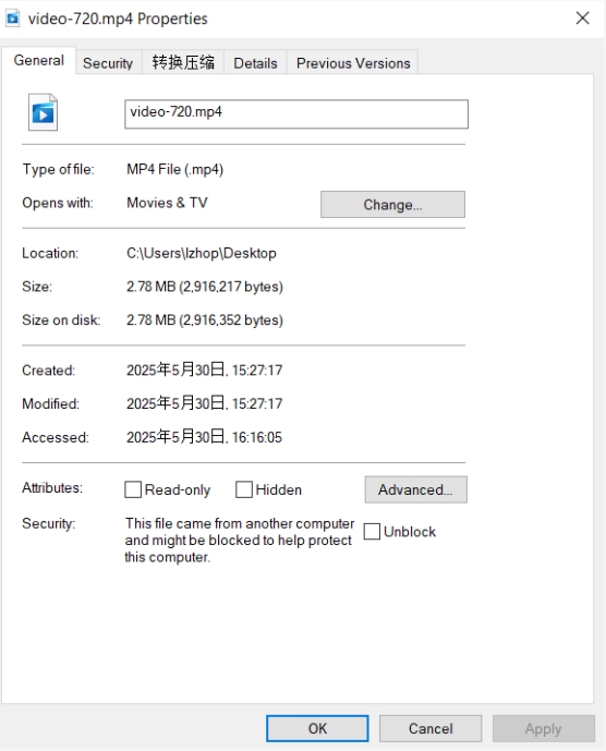
ffmpeg -i .\video-720.mp4 -q:v 25 output.mp4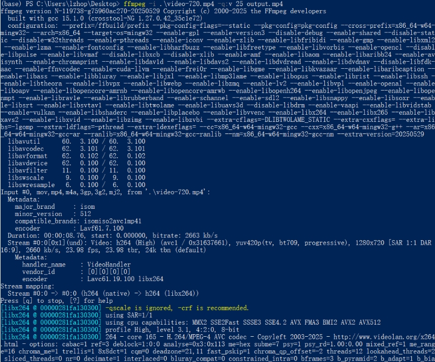 Original video:
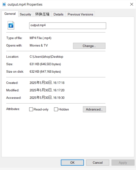
Compressed video:
The video was compressed from 2.78MB to 632KB, a compression of about 77.8%:
|  |
|  | |:--😐:--😐
Reference:
The reference and design files are listed below:
- The 3D design file (.f3d) can be found in my repository:https://gitlab.fabcloud.org/academany/fabacademy/2025/labs/unnc/students/xu-sun/-/blob/main/docs/assignments/week2/resource_week2/week2-Laser machine v3 v2.f3d?ref_type=heads