Appearance
Week 4 - Embedded programming
Assignments
Group Assignment
- Demonstrate and compare the toolchains and development workflows for available embedded architectures
Individual Assignment
- Browse through the data sheet for your microcontroller
- Write a program for a microcontroller, and simulate its operation, to interact (with local input &/or output devices) and communicate (with remote wired or wireless connections)
- extra credit: test it on a development board
- extra credit: try different languages &/or development environments
Group Working
My group work is attached here: https://fabacademy.org/2025/labs/unnc/assignments/week4/week04.html
Individual Working
Datasheet
I read the datasheets for the Arduino Uno R4 and Raspberry Pi 4B, focusing on their processor architecture, I/O resources, communication interfaces, and power management.
Arduino Uno R4
The core MCU of the Arduino Uno R4 is the Renesas RA4M1. This chip is based on the ARM Cortex-M4 architecture, runs at a frequency of 48MHz, and features 32KB SRAM and 256KB flash memory. Compared to the Uno R3, the processor has been upgraded to a 32-bit 48MHz Renesas RA4M1, significantly improving performance. The SRAM has increased from 2KB to 32KB, and flash memory from 32KB to 256KB, providing more space for complex applications and data processing. See Datasheet.
 Reference:
https://docs.arduino.cc/resources/datasheets/ABX00087-datasheet.pdf?_gl=1*1o5mzgy*_up*MQ
Core Specifications
| Parameter | Specification |
|---|---|
| Name | Arduino Uno R4 |
| Microcontroller | Renesas RA4M1 (ARM Cortex-M4) |
| Operating Voltage | 3.3V |
| Input Voltage | 6-24V (recommended 7-12V) |
| GPIO Pins | 20 (14 digital I/O + 6 analog inputs) |
| Digital Pins | 14 (including 4 PWM outputs) |
| PWM Pins | 4 (GPIO 3/5/6/9/10) |
| Analog Input Pins | 6 (10-bit ADC) |
| I2C Port | 1 (A4/SDA, A5/SCL) |
| UART Port | 1 (Hardware Serial) |
| SPI Port | 1 (ICSP header) |
| Flash Memory | 256KB Flash |
| SRAM | 32KB |
| EEPROM | 8KB |
| Clock Speed | 48MHz |
The detailed PCB layout of the Arduino UNO R4 board is shown below:
 Reference:
https://docs.arduino.cc/resources/schematics/ABX00087-schematics.pdf
MCU Architecture Analysis
The Arduino Uno R4 uses the Renesas RA4M1 microcontroller (Model: R7FA4M1AB3CFM), which is a high-performance MCU based on the ARM Cortex-M4 core. By analyzing the chip's architecture and functional characteristics, we can gain a deeper understanding of its advantages in WS2812 LED control applications:
Overall Chip Architecture
 From the block diagram, we can see that the RA4M1 adopts an efficient system architecture:
- 48MHz ARM Cortex-M4 core
- Multi-layer bus matrix ensuring efficient peripheral access
- Rich timer and PWM resources
- Complete clock management system
Pin Function Assignment


Raspberry Pi 4B
The Raspberry Pi 4B is a microcomputer powered by the Broadcom BCM2711 chip, featuring a quad-core Cortex-A72 architecture with a clock speed of 1.5GHz. It offers a range of RAM options, from 1GB to 8GB, and includes dual Micro-HDMI ports, dual-band wireless connectivity, Bluetooth 5.0, a Gigabit Ethernet port, four USB ports, and a 40-pin GPIO header. It supports 4K display output and 4K@60fps hardware video decoding. The device operates on a 5V/3A power supply, making it a versatile and powerful option for various computing tasks.Raspberry Pi 4B Datasheet

Core Specifications
| Parameter | Description |
|---|---|
| Name | Raspberry Pi 4 Model B |
| SoC | Broadcom BCM2711 |
| Operating Voltage | 5V (via USB-C) |
| Input Voltage | 5V |
| GPIO Pin Count | 40 |
| Digital Pins | 40 (All GPIO pins are digital pins) |
| PWM Pins | 4 (GPIO12/13/18/19, 2 independent channels) |
| Analog Input Pins | None (requires external ADC module) |
| I2C Ports | 2 (I2C-0 and I2C-1) |
| UART Ports | 2 (Main UART + Mini UART) |
| SPI Ports | 2 (SPI0 and SPI1) |
| Storage | microSD card (supports UAS boot) |
| Memory | 1/2/4/8GB LPDDR4 |
| Video Output | Dual micro HDMI (supports 4K60) |
| Network Interface | Gigabit Ethernet + Dual-band WiFi 5 |
| Clock Speed | 1.5GHz (Quad-core Cortex-A72) |
Arduino IDE
Arduino IDE is an integrated development environment officially provided by Arduino, which is used to write, compile and upload code to Arduino development boards. It supports a variety of Arduino board types, uses a simple interface and C/C++-based programming language, and is suitable for beginners and experienced developers. Arduino IDE provides rich library support and sample code, and is widely used in electronic prototype development, education and teaching, and maker projects.
Download the Arduino IDE from the arduino.cc.
 In the Boards Manager, select and download the Arduino Uno R4 board library.
 Connect the Arduino Uno R4 to your computer.

Development board test
Case 1: Arduino Uno R4 WS2812 Control
In this case, we use the Arduino Uno R4 microcontroller to drive two custom hexagonal PCBs. Each PCB is evenly populated with 18 WS2812 programmable RGB LEDs. The goal of this case is to create a smooth chasing light effect, where the LEDs light up in a preset sequence and timing across the two hexagonal boards, forming a seamless visual animation effect.
1. Hardware Setup
Required Components
- WS2812 LED strip
- Arduino Uno R4
- DuPont cables
2. Arduino Programming Basics
Arduino programming combines features of C and C++. In a new folder, the file by default contains two functions: setup() and loop(). Their functions are as follows:
setup() Function
- Mainly used for initialization tasks, such as configuring pin modes, initializing serial communication baud rates, assigning variable values, etc.
- This function is executed only once when the program starts.
loop() Function
- This function continuously loops and executes the main functions of the program, such as reading sensor data, controlling actuators, processing data, etc.
3. Microcontroller Simulation
- The WS2812 LED strip has three wires:
- VCC (Power): Connect to the 5V power supply
- GND (Ground): Connect to Arduino GND
- DIN (Data Input): Connect to Arduino digital pin 2 (PWM supported)
- Connection steps:
- Power connection:
- Connect the VCC wire to the external 5V power supply
- Connect the GND wire to the power ground and Arduino GND The following hardware connection diagram, designed using the Wokwi online simulation platform, illustrates the detailed wiring configuration between the WS2812 LED and Arduino Uno R4:

Based on the simulation circuit above, I designed a hexagonal PCB board with three WS2812 programmable RGB LEDs evenly distributed along each edge, creating a symmetrical lighting arrangement.

4. Code Implementation
The code uses the FastLED library, which can be installed via the Arduino IDE's Library Manager FastLED Library. This implementation creates a dynamic chasing light effect on two hexagonal PCBs with WS2812 LEDs.
Code Analysis
C
#include <FastLED.h>

// Configuration parameters
#define LED_PIN 6         // P106 pin for WS2812 data control
#define NUM_LEDS 36       // Total LEDs (18 LEDs × 2 PCBs)
#define PCB_COUNT 2       // Two hexagonal PCBs
#define LEDS_PER_PCB 18   // 18 LEDs per PCB
#define COLUMNS 9         // Number of columns (half of LEDS_PER_PCB)
#define UPDATE_INTERVAL 80 // Animation update interval (ms)

// Global variables
CRGB leds[NUM_LEDS];       // Array to store LED RGB values
uint8_t currentColumn = 0; // Tracks current active column
unsigned long lastUpdate;  // Timestamp for interval control

void setup() {
  // Initialize FastLED with WS2812 configuration
  FastLED.addLeds<WS2812, LED_PIN>(leds, NUM_LEDS);
  FastLED.setBrightness(50);  // Set moderate brightness (0-255)
  FastLED.clear(true);        // Clear all LEDs initially
}

void loop() {
  unsigned long currentMillis = millis();

  // Check if it's time for the next animation frame
  if (currentMillis - lastUpdate >= UPDATE_INTERVAL) {
    lastUpdate = currentMillis;

    // Turn off previous LEDs
    for (uint8_t p = 0; p < PCB_COUNT; p++) {
      uint16_t base = p * LEDS_PER_PCB;      // Calculate starting index for each PCB
      uint8_t prevCol = (currentColumn + COLUMNS - 1) % COLUMNS;  // Calculate previous column

      // Turn off symmetrical LED pairs
      leds[base + prevCol] = CRGB::Black;
      leds[base + (LEDS_PER_PCB - 1) - prevCol] = CRGB::Black;
    }

    // Light up new LEDs
    for (uint8_t p = 0; p < PCB_COUNT; p++) {
      uint16_t base = p * LEDS_PER_PCB;

      // Set new LED pairs with HSV color (red at full saturation and brightness)
      leds[base + currentColumn] = CHSV(0, 255, 255);
      leds[base + (LEDS_PER_PCB - 1) - currentColumn] = CHSV(0, 255, 255);
    }

    // Move to next column
    currentColumn = (currentColumn + 1) % COLUMNS;

    // Update physical LEDs
    FastLED.show();
  }
}
After successfully uploading the program to the microcontroller, the following video demonstrates the dynamic lighting effects in action:
Case 2: Raspberry Pi 4B Control Servo
This case uses the GPIO18 pin of the Raspberry Pi 4B to control the servo via PWM signals, achieving precise angle positioning within the range of 0° to 180°. The program cyclically controls the servo to move between 0°, 90°, and 180°, demonstrating precise position control and basic motion sequence programming for the servo using the Python RPi.GPIO library.
1. Hardware Configuration
Required Components
- Raspberry Pi 4B
- JX PDI-622MG Servo
- 5V/2A Power Supply
- DuPont Wires
2. Install Raspberry Pi System
- Preparation:
- Download and install Raspberry Pi Imager (the official Raspberry Pi flashing tool)
- Prepare a microSD card with a capacity of at least 8GB
- Prepare a card reader to connect the microSD card to the computer

System Flashing:
- Open Raspberry Pi Imager

- Click "Choose OS" and select Raspberry Pi OS (64-bit) from the list, then click "Choose Storage" and select the microSD card to flash.
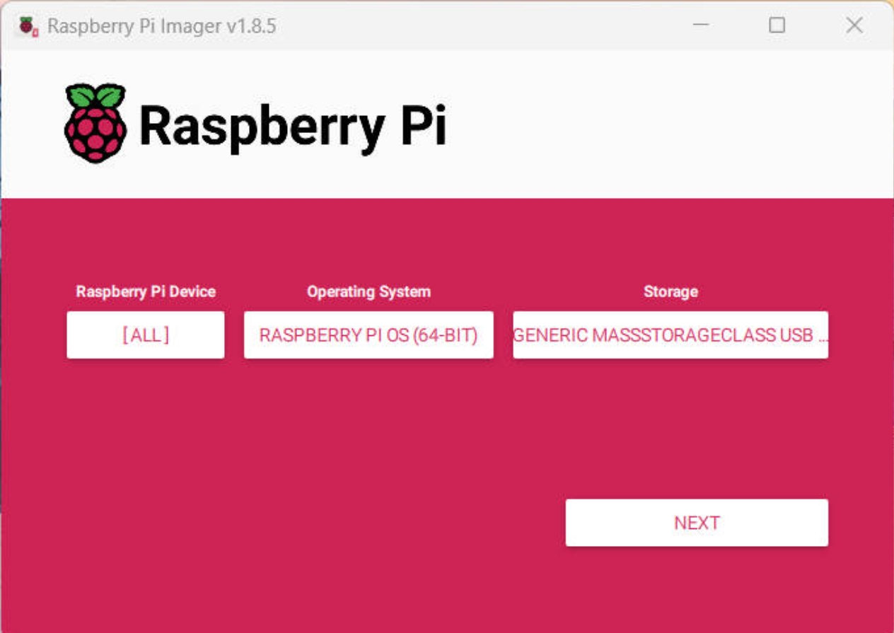
- After clicking "Next," you can configure some settings:
- WiFi network configuration
- Username and password
- Hostname
- SSH switch, etc.
- Click "Write" to start flashing the system.

First Boot:
- Insert the flashed microSD card into the Raspberry Pi
- Connect the power (it is recommended to use the official power adapter, output 5V/3A)
- Wait for the system to automatically complete the initialization configuration

VNC Remote Control:
To facilitate remote operation of the Raspberry Pi, I used the VNC (Virtual Network Computing) remote desktop solution:
- First, download and install VNC Viewer

Enable the VNC Server on the Raspberry Pi (through raspi-config in the Interface Options)

Use the
ifconfigcommand in the Raspberry Pi terminal to check its IP address (in this case, it is 10.0.0.92)
 4. Open VNC Viewer and enter the Raspberry Pi's IP address in the connection bar

Enter the Raspberry Pi's username and password to complete authentication

Once connected successfully, you can control the Raspberry Pi's graphical interface remotely through VNC

Configure Hardware Interfaces:
- Open the terminal and enter
sudo raspi-configto enter the configuration menu, then select "Interface Options"


Enable the following interfaces one by one:
- GPIO (for servo control)
- PWM (to generate servo control signals)

After completing the setup, select "Finish" and reboot the Raspberry Pi
You can verify if the interfaces are enabled with the following commands:
gpio readallto check the GPIO statusls /dev/i2c*to check I2C
- Open the terminal and enter
3. Raspberry Pi Python Programming Basics
Raspberry Pi supports various programming languages, but Python is the most popular due to its simplicity and extensive library support. This example uses the RPi.GPIO library to control the servo, achieving precise angle control and motion sequencing.
Code Writing
Install Dependencies
Run the following commands in the Raspberry Pi terminal to install the necessary libraries:
bash
# Update package list
sudo apt update

# Install Python3 package manager pip
sudo apt install python3-pip

# Install RPi.GPIO library - a Python library for controlling Raspberry Pi GPIO pins
# --break-system-packages flag allows installation in system Python environment
pip3 install RPi.GPIO --break-system-packages

4.Code Implementation
python
import RPi.GPIO as GPIO
import time

# Configuration parameters
SERVO_PIN = 18          # Servo control pin (GPIO18)
FREQ = 50              # PWM frequency (50Hz)
MIN_DUTY = 2.5         # Minimum duty cycle (0 degrees)
MAX_DUTY = 12.5        # Maximum duty cycle (180 degrees)

# Initialize GPIO settings
GPIO.setmode(GPIO.BCM)
GPIO.setup(SERVO_PIN, GPIO.OUT)
pwm = GPIO.PWM(SERVO_PIN, FREQ)
pwm.start(0)

def angle_to_duty_cycle(angle):
    """Convert angle to duty cycle"""
    duty = MIN_DUTY + (MAX_DUTY - MIN_DUTY) * (angle / 180)
    return duty

def set_angle(angle):
    """Set servo angle"""
    duty = angle_to_duty_cycle(angle)
    pwm.ChangeDutyCycle(duty)
    time.sleep(0.3)  # Wait for the servo to reach position

try:
    while True:
        # Demonstrate servo movement sequence
        print("Moving to 0 degrees")
        set_angle(0)
        time.sleep(1)

        print("Moving to 90 degrees")
        set_angle(90)
        time.sleep(1)

        print("Moving to 180 degrees")
        set_angle(180)
        time.sleep(1)

        print("Moving to 90 degrees")
        set_angle(90)
        time.sleep(1)

except KeyboardInterrupt:
    print("Program exiting")
    pwm.stop()
    GPIO.cleanup()
4. Hardware Connections and Operation
This example uses the GPIO18 pin on the Raspberry Pi to control the servo via PWM signals.
- Servo Connection:
- Red wire (VCC): Connect to the Raspberry Pi's 5V pin
- Brown wire (GND): Connect to the Raspberry Pi's GND pin
- Orange wire (Signal wire): Connect to GPIO18 (PWM pin)
 2. Run the Program
bash
sudo /bin/python /home/xusun/servo_control.py
Case 3: XIAO ESP32C3
Building upon Arduino/Raspberry Pi cases, I further explored the Seeed Studio XIAO ESP32C3 development board with two embedded control implementations:

- Pressing the toggle switch activates LED1 (ON) while deactivating LED2 (OFF), creating mutually exclusive visual indicators.
cpp
const int LED1=8;
const int LED2=9;
int val=0;
void setup()
{
  pinMode(LED1, OUTPUT);
  pinMode(LED2, OUTPUT);
  pinMode(7, INPUT);
}
void loop(){
val=digitalRead(7);
  if(val==HIGH)
{
    digitalWrite(LED1,HIGH);
    digitalWrite(LED2,LOW);
}
else
{
    digitalWrite(LED2,HIGH);
    digitalWrite(LED1,LOW);
}
delay(1000);
}
 2. Implemented real-time distance monitoring using HC-SR04 ultrasonic sensor. Triggers LED activation when proximity detection under 200 mm, with serial data visualization.
cpp
#define TrigPin A0
#define EchoPin A1
int count = 0;
long duration;


void setup() {
 Serial.begin(115200);
 pinMode(TrigPin, OUTPUT);
 pinMode(EchoPin, INPUT);
 digitalWrite(TrigPin, LOW);
 delay(1);
 pinMode (D10, OUTPUT);

}

void loop() {
 Serial.println(count++);
 Serial.println(getDistance());
 Serial.println("");
 Serial.println("");
 delay(1000);
 int distance= getDistance();
 if (distance<200){
   digitalWrite(D10, HIGH);
 }
 else {
  digitalWrite(D10, LOW);
 }
}

long getDistance() {
 digitalWrite(TrigPin,LOW);
 delayMicroseconds(2);
 digitalWrite(TrigPin, HIGH);
 delayMicroseconds(10);
 digitalWrite(TrigPin,LOW);
 duration = pulseIn(EchoPin,HIGH);
 return duration * 0.34029 /2;
}
Reference:
The reference and design files are listed below:
The code file for Arduino UNO R3 controlling ws2812 light strip in WOKWI can be found in my repository:https://gitlab.fabcloud.org/academany/fabacademy/2025/labs/unnc/students/xu-sun/-/blob/main/docs/assignments/week4/resource-week4/week4-ws2812control.ino?ref_type=heads
The code files for controlling the servos of the Raspberry Pi 4B can be found in my repository:https://gitlab.fabcloud.org/academany/fabacademy/2025/labs/unnc/students/xu-sun/-/blob/main/docs/assignments/week4/resource-week4/week3-servocontrol.py?ref_type=heads
The code file for XIAO ESP32 C3 controlling ultrasonic sensor can be found in my repository:https://gitlab.fabcloud.org/academany/fabacademy/2025/labs/unnc/students/xu-sun/-/blob/main/docs/assignments/week4/resource-week4/week4-SR04Demo.ino?ref_type=heads
The LED light case code file for XIAO ESP32 C3 can be found in my repository:https://gitlab.fabcloud.org/academany/fabacademy/2025/labs/unnc/students/xu-sun/-/blob/main/docs/assignments/week4/resource-week4/week4-LEDDemo.ino?ref_type=heads