Appearance
Week 7 - Computer controlled machining
Assignments
Group Assignment
- Do your lab's safety training test runout, alignment, fixturing, speeds, feeds, materials, and toolpaths for your machine
Individual Assignment
- Make (design+mill+assemble) something big (~meter-scale)
- Extra credit: don't use fasteners or glue
- Extra credit: include curved surfaces
Group working
My group work is attached here: https://fabacademy.org/2025/labs/oshanghai/students/shuijiao-li/assignments/week07/
Individual working
I used a 12mm birch wood board, which has a standard size of 1220 × 2440 × 12mm. Before processing, ensure to check and remove any burrs or sharp edges.
Design in fusion 360
I design one desk and the concept reference from opendesk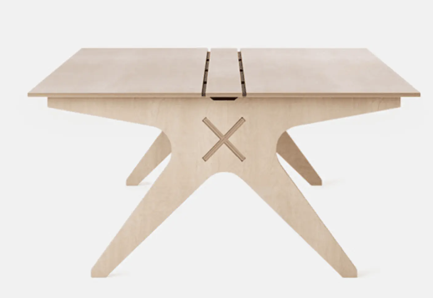
The following outlines our design process and results. I utilized Fusion 360's parametric design to define key parameters, enabling easy reuse of the design for similar projects in the future. 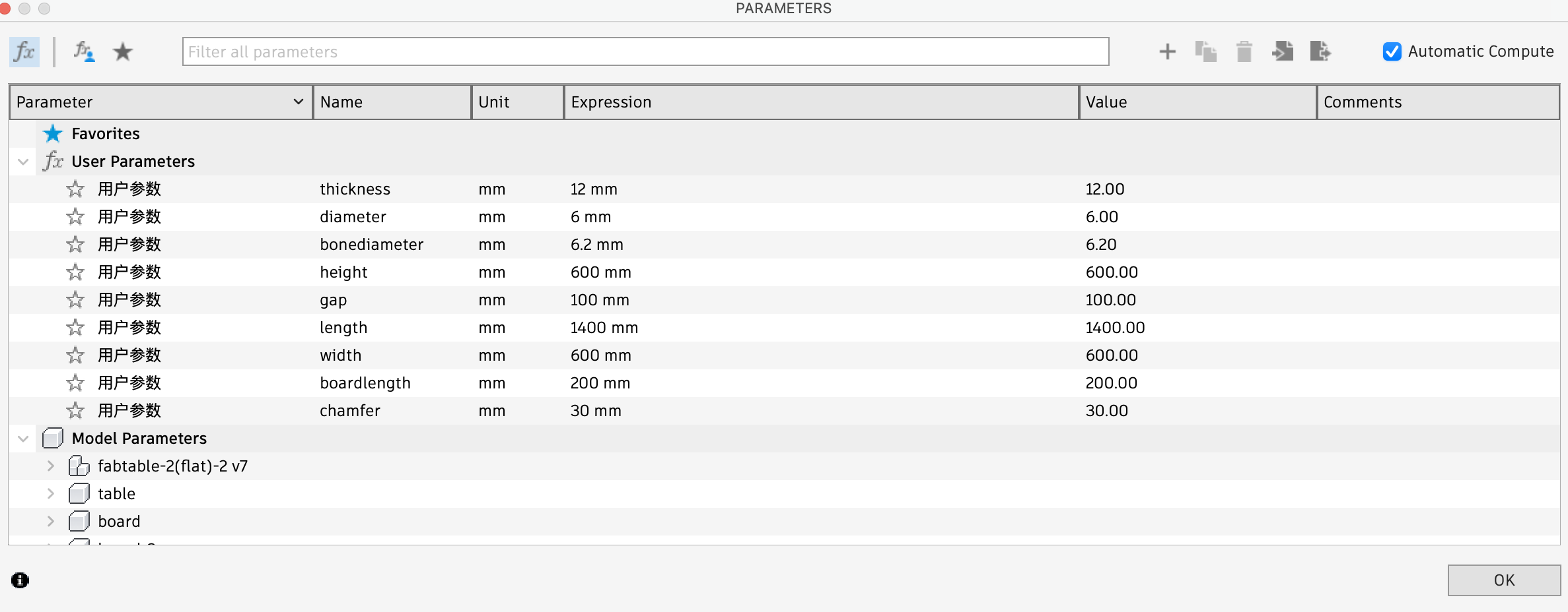 I use dogbone concept to design assemble detail.
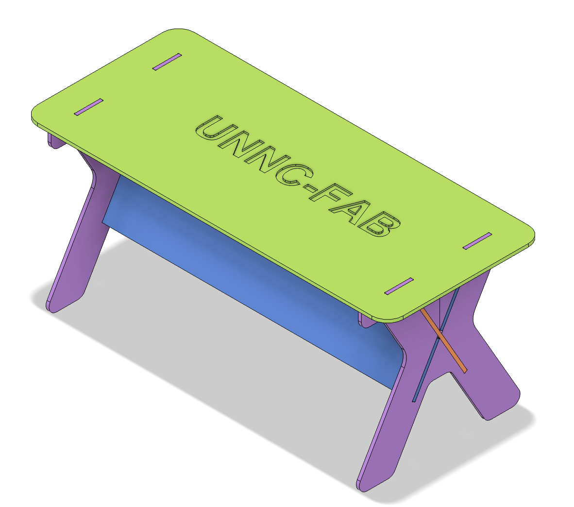
 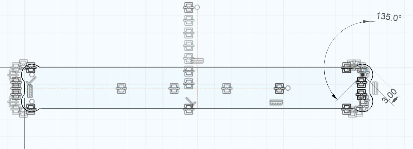 I designed four components named table, board, board-2, and leg1, and then assembled them to complete the design.
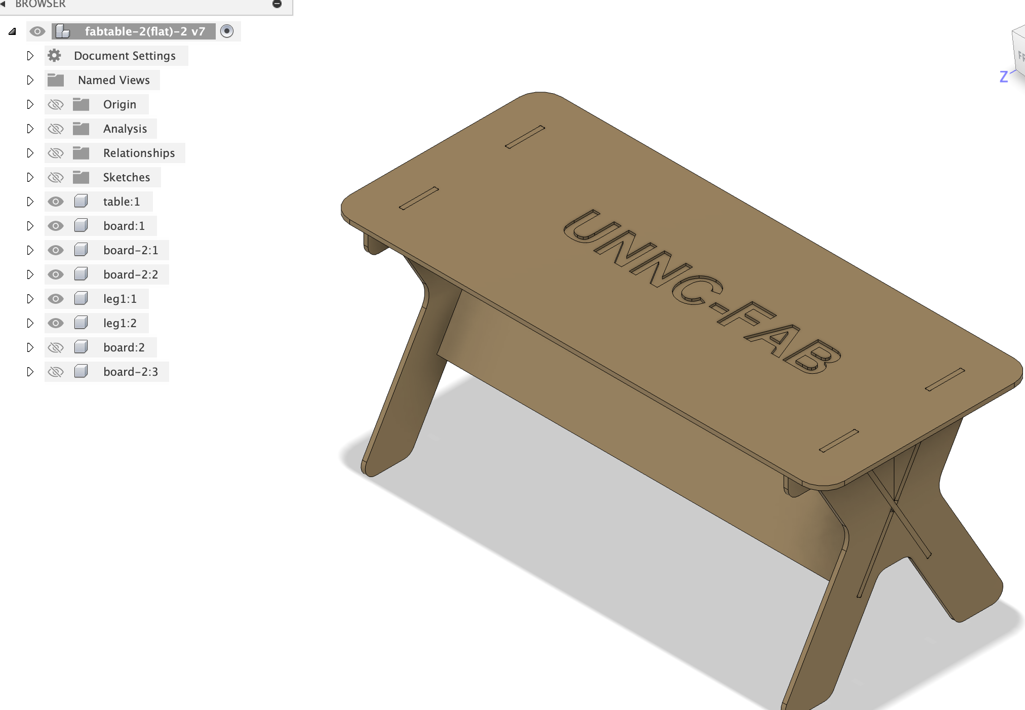
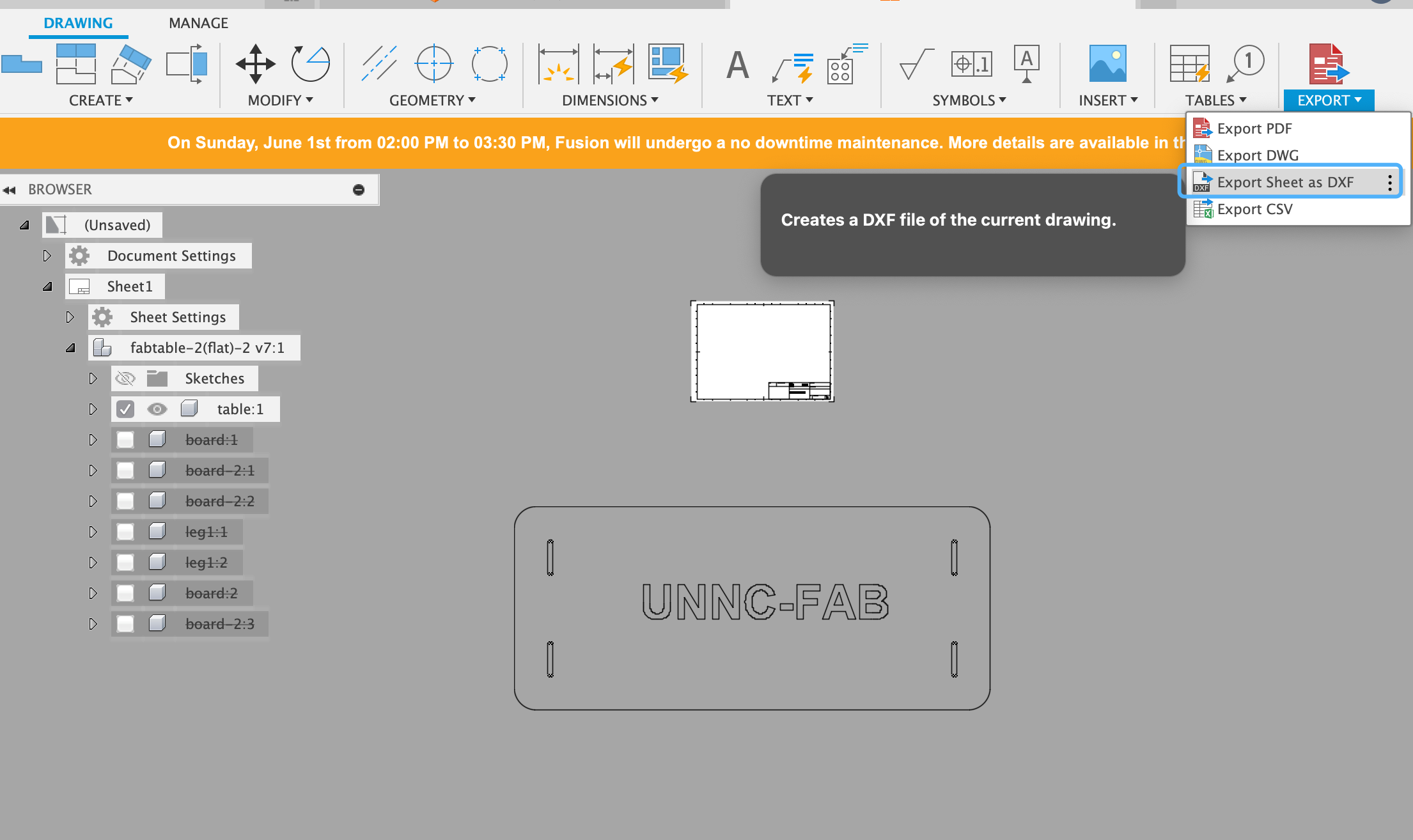
 Then output dxf file in fusion 360 drawing
 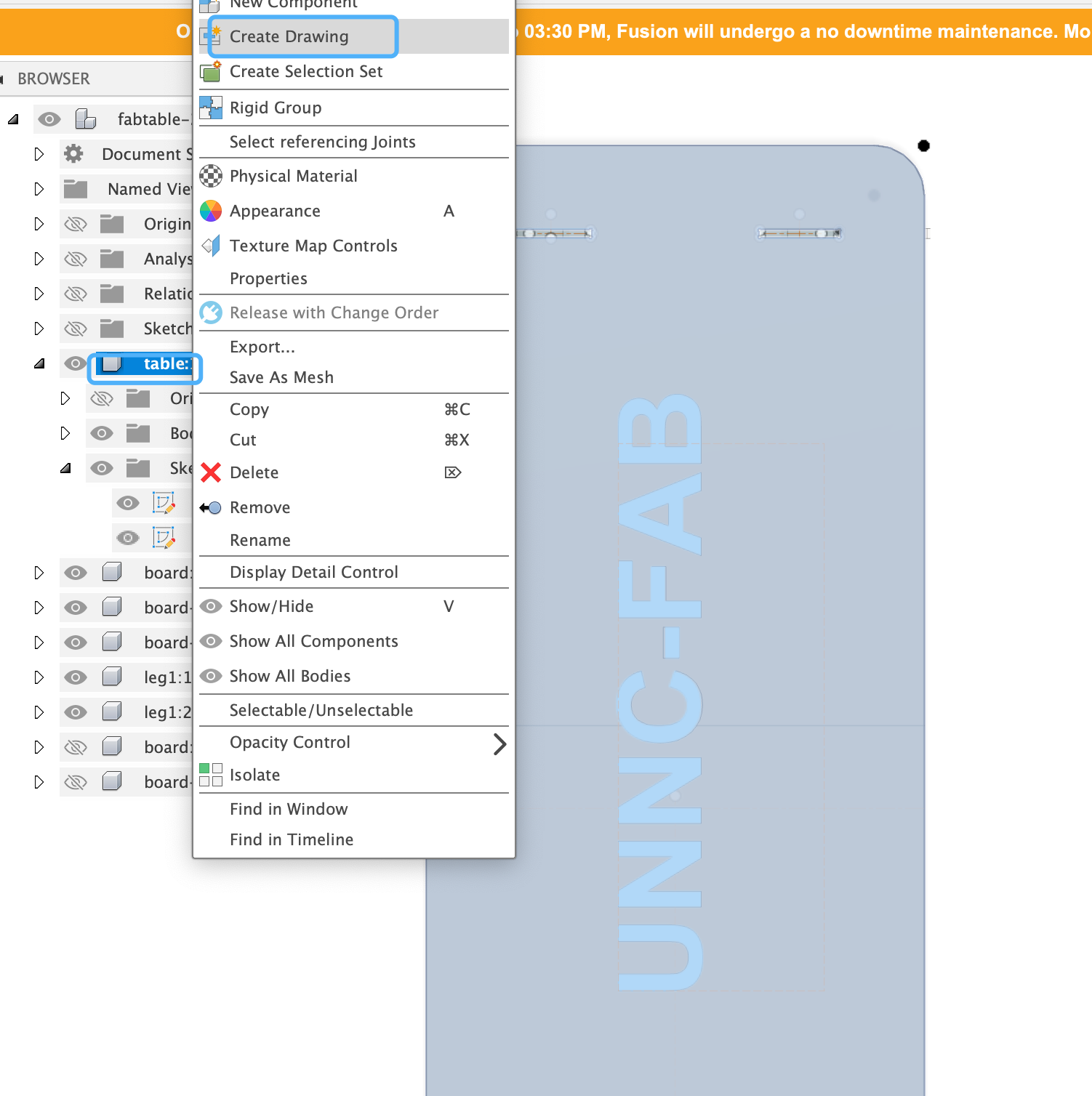 Remember to select a scale of 1:1 before exporting the design as a DXF file. This ensures that the dimensions are accurate for manufacturing or further processing.
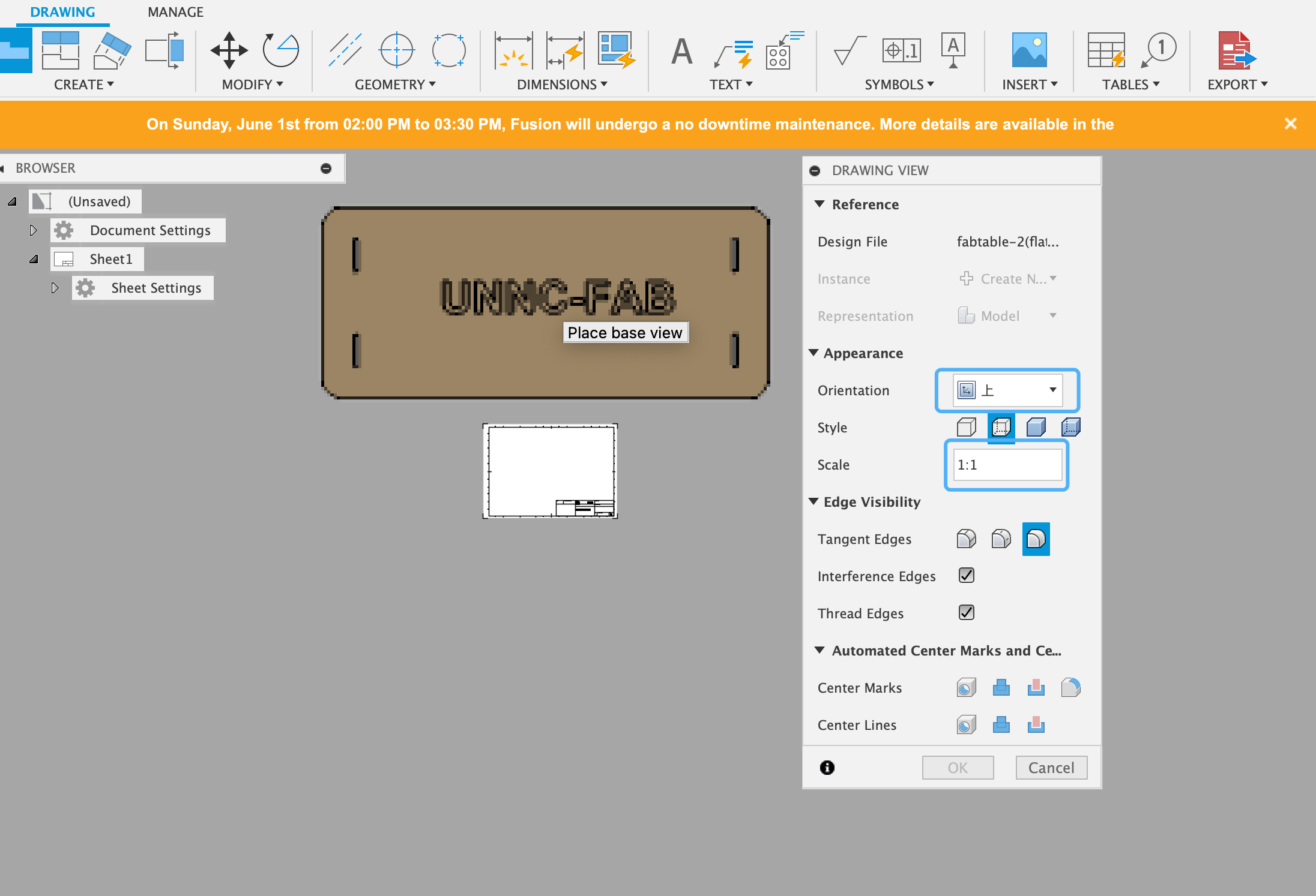
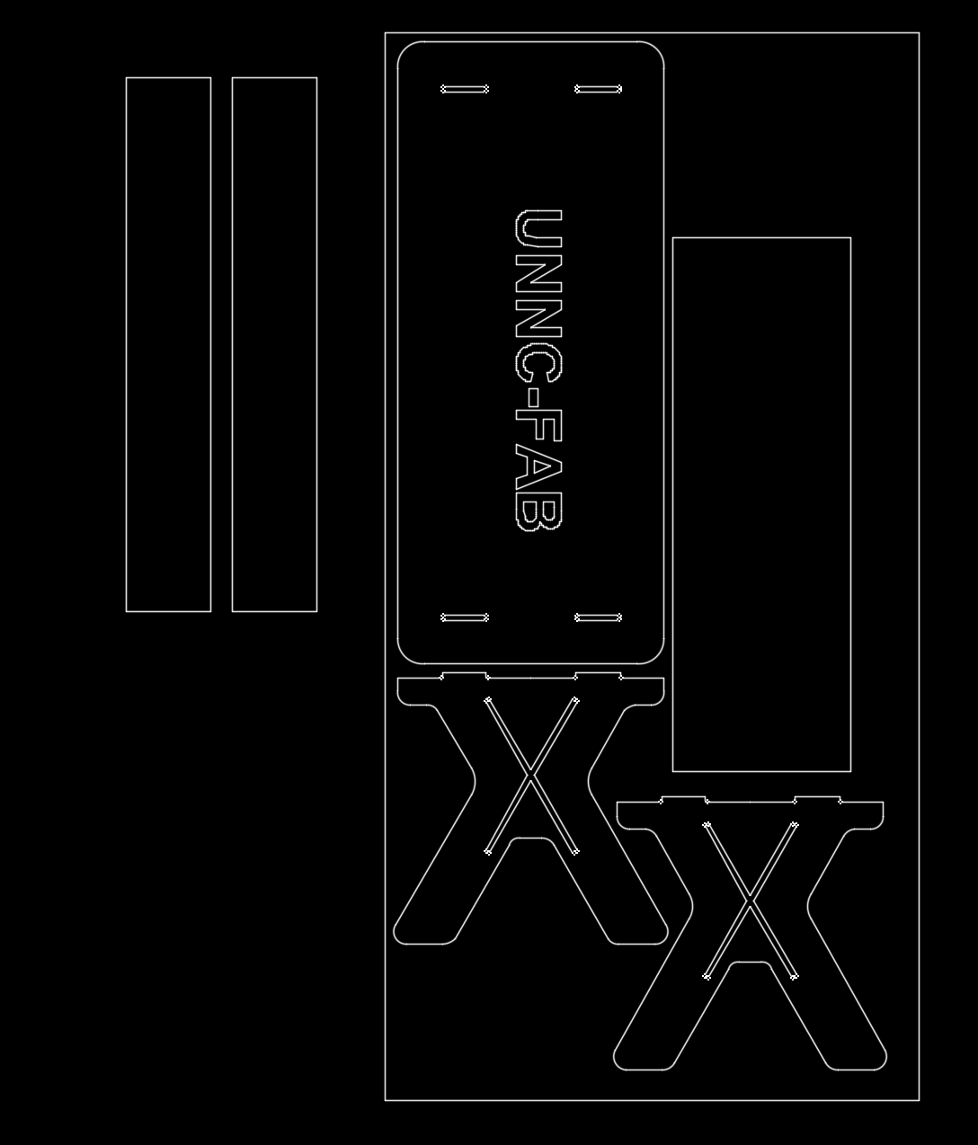
 For the other three components, I used the same method. Then, I employed AutoCAD to arrange the four drawings together:
- Remove the drawing block diagram.
- Draw a rectangle with dimensions 1220 × 2440.
- Place the components inside the rectangle while trying to optimize material usage.
The following is the result:
CAM
JD CAM software
I use JD software to define the path,spindle speed,feed,etc
Import data and confirm unit 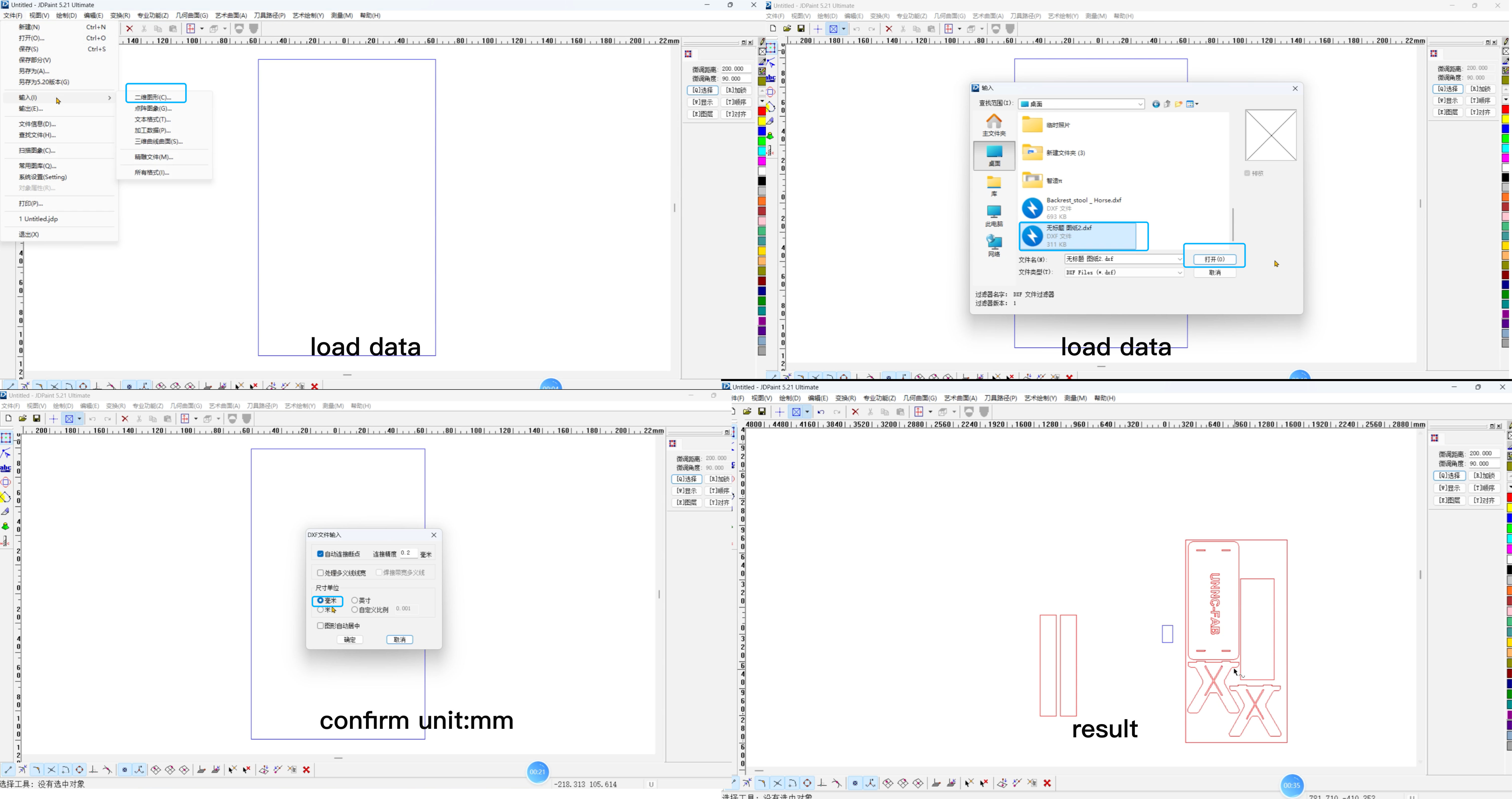 Confirm the inner design areas that need to be cut (indicated by the green line). These are the regions where the cutter will follow to shape the components from the material.
  For inside design we can reference the following setting
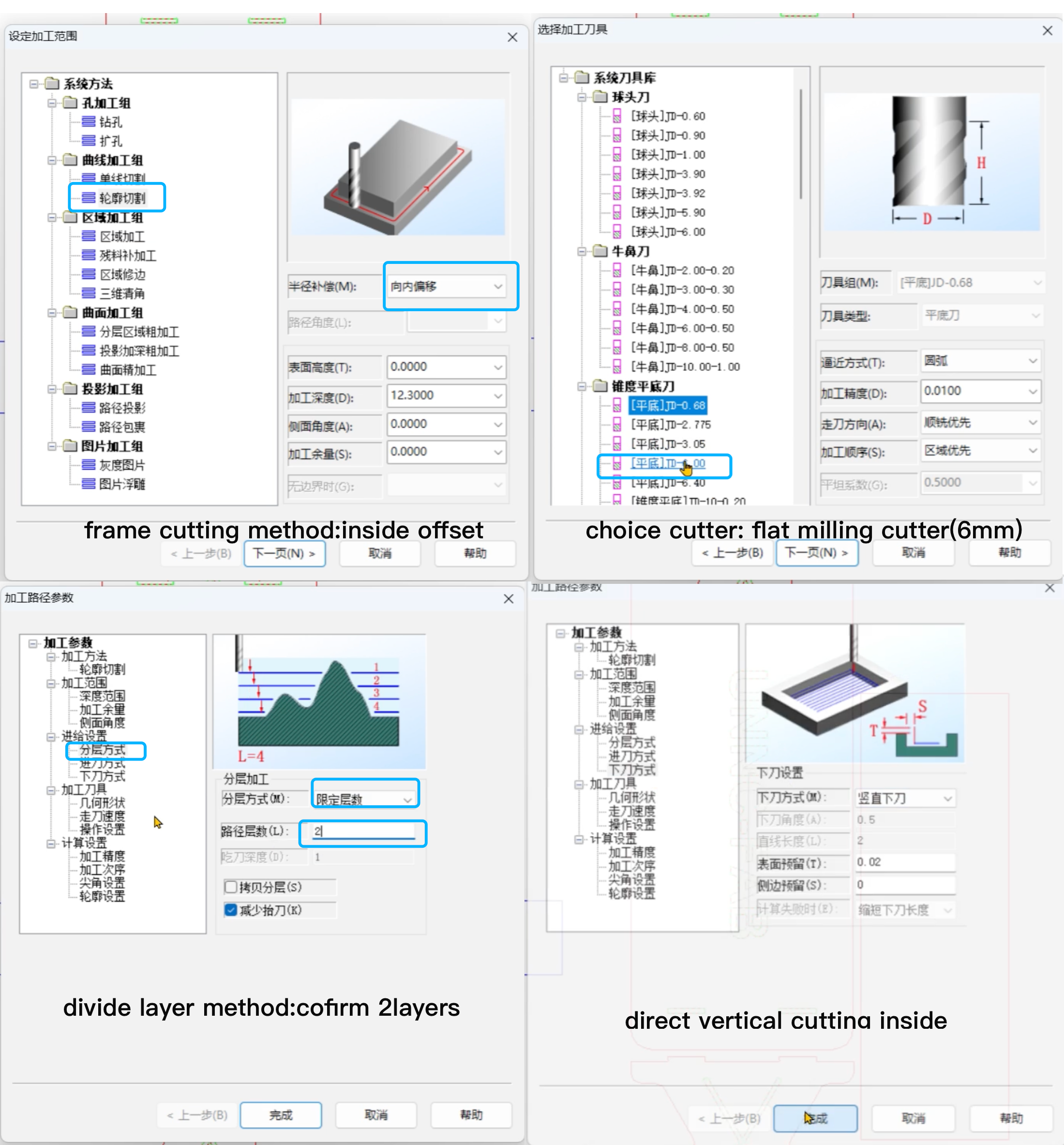
Confirm engrave part 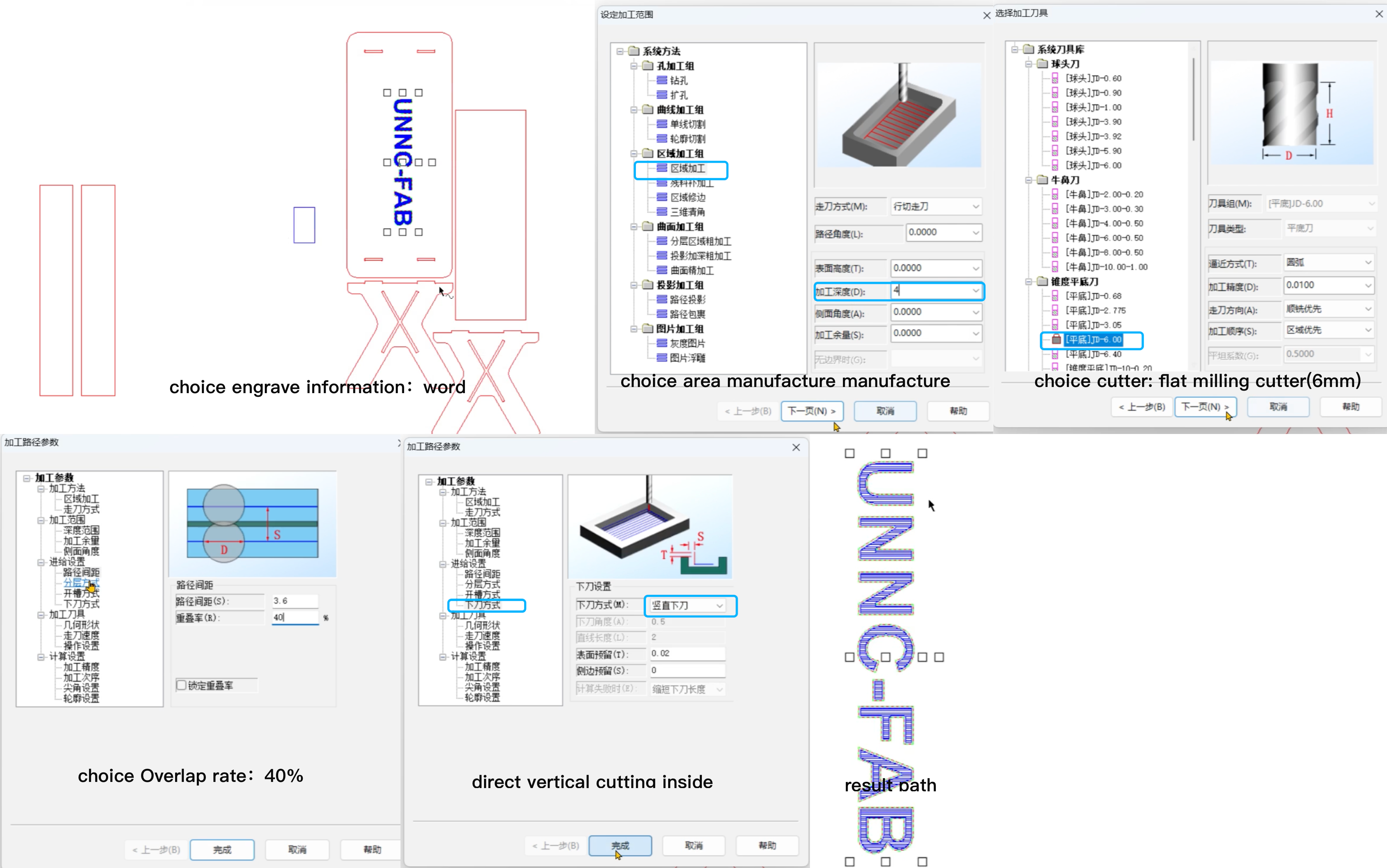 Confirm the outside frame
 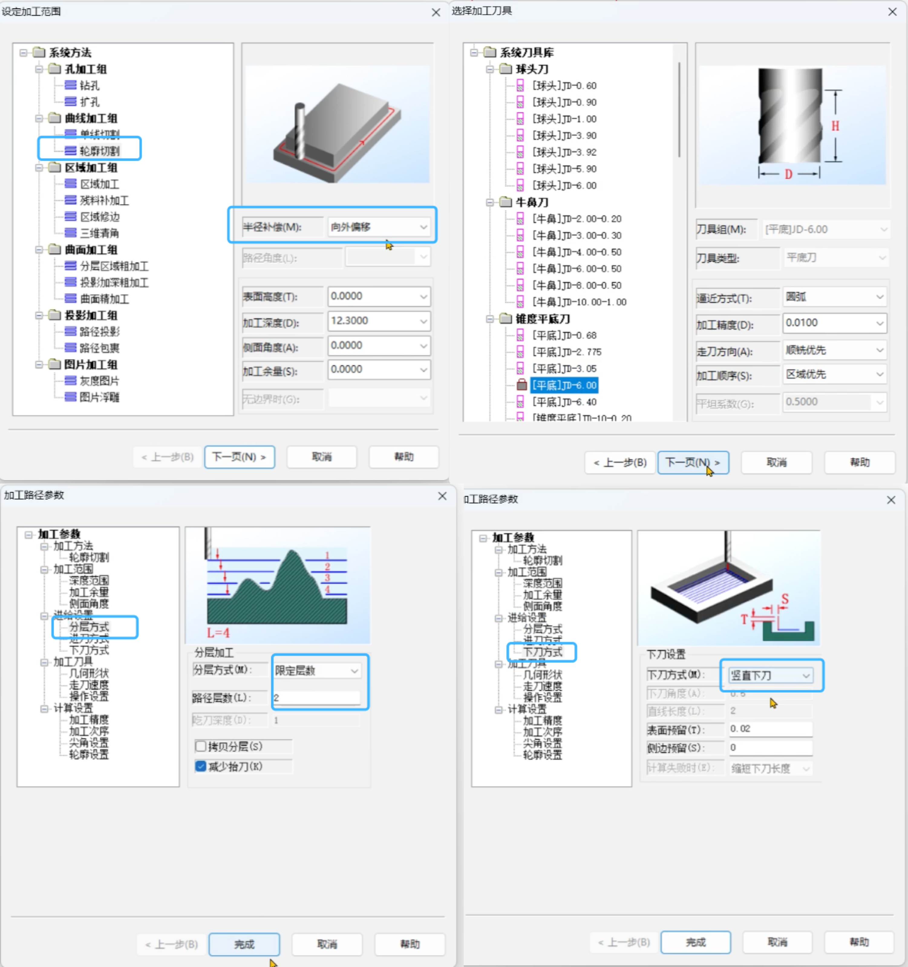 The red path represents the frame, outlining the outer boundary of the design
 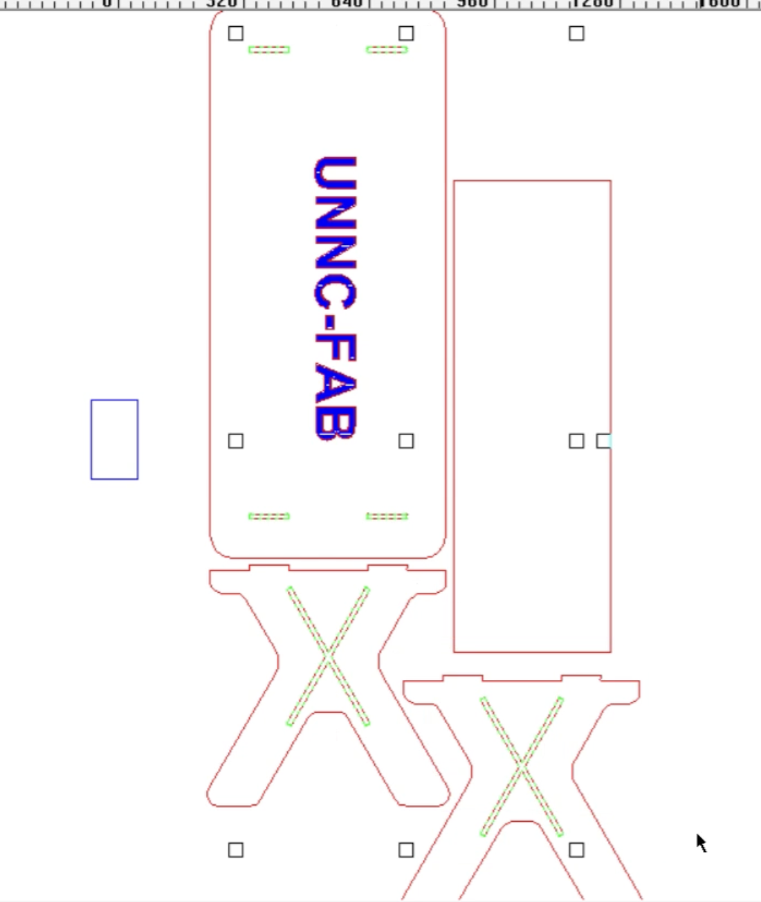 Choose the paths that need to be manufactured, then move them accordingly. The blue part will represent the sections that require cutting or manufacturing, while the red part indicates the actual design. This distinction helps to ensure that only the necessary areas are processed.
 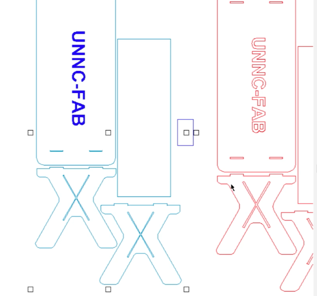 Output data
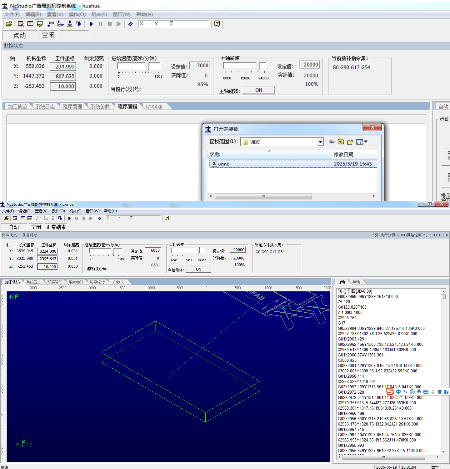
 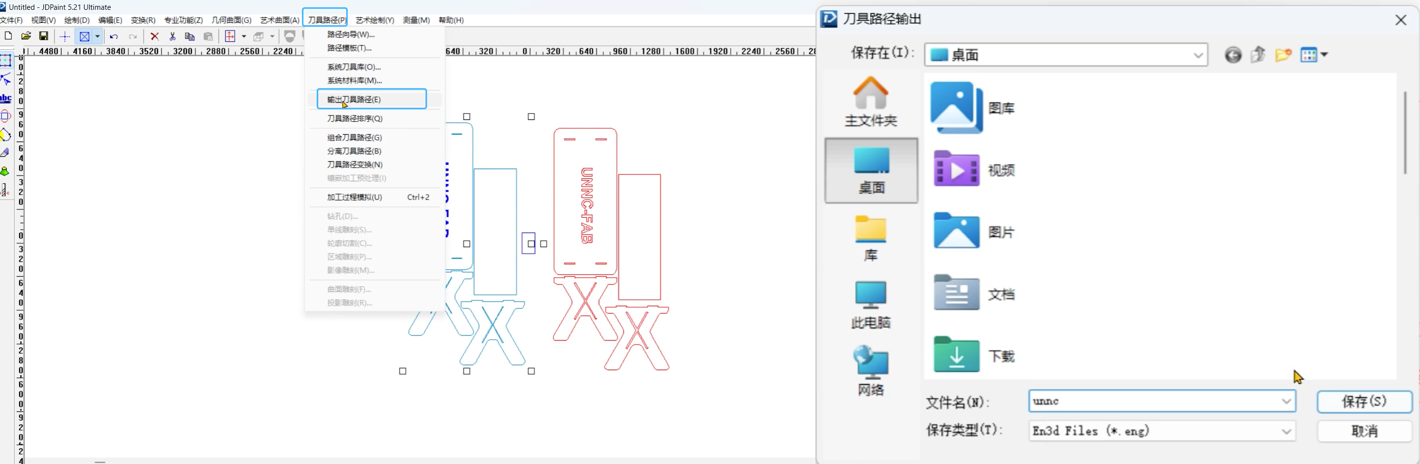 In this NCConverter software, we need to convert the .eng file format into a machine processed file(.nc).
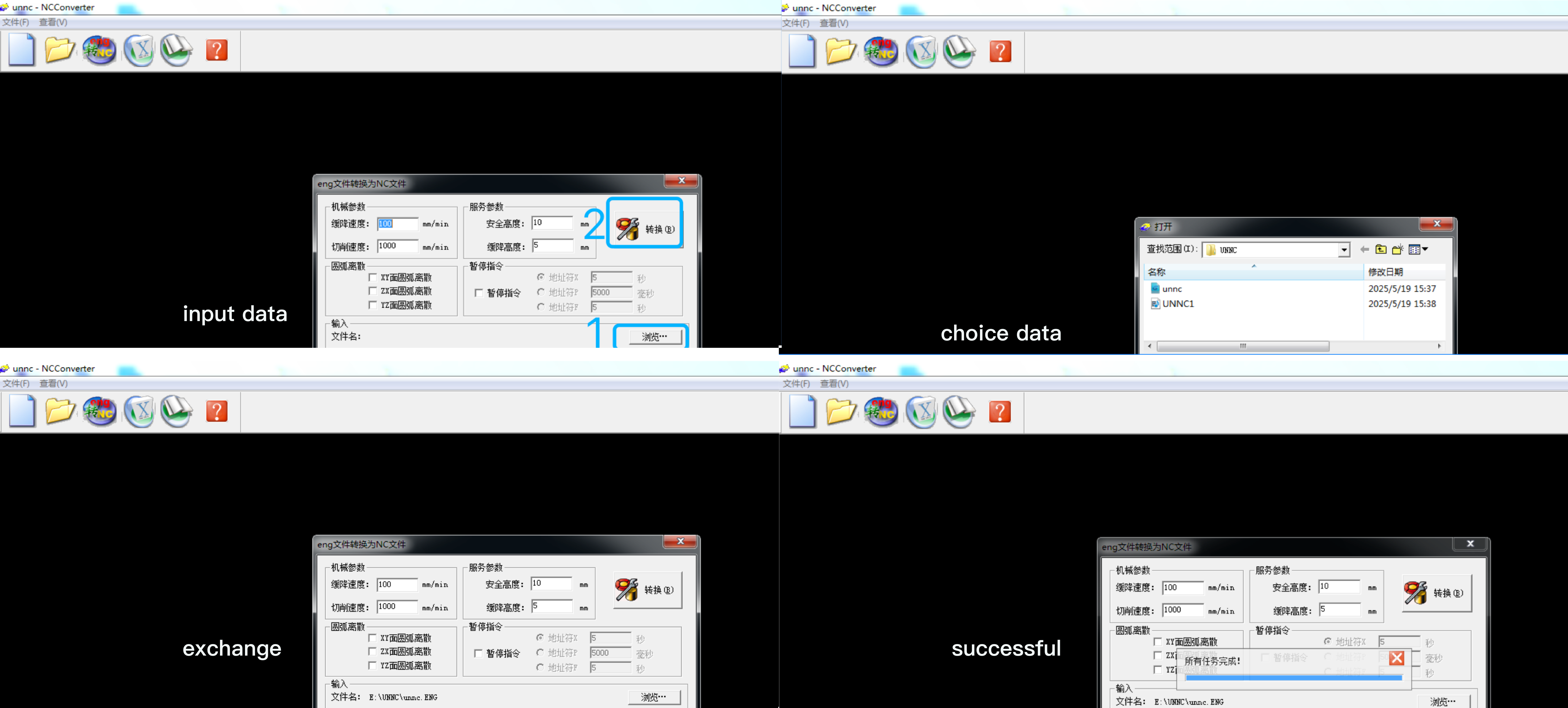
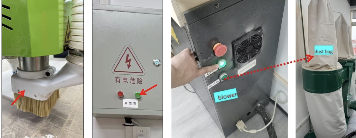
Machine prepare
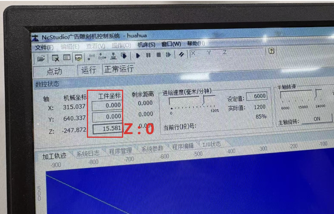
Use keyboard to move spindle x,y,z 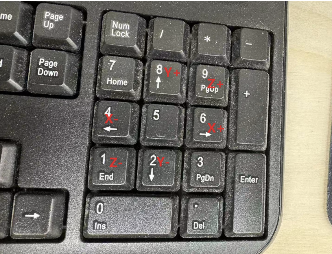
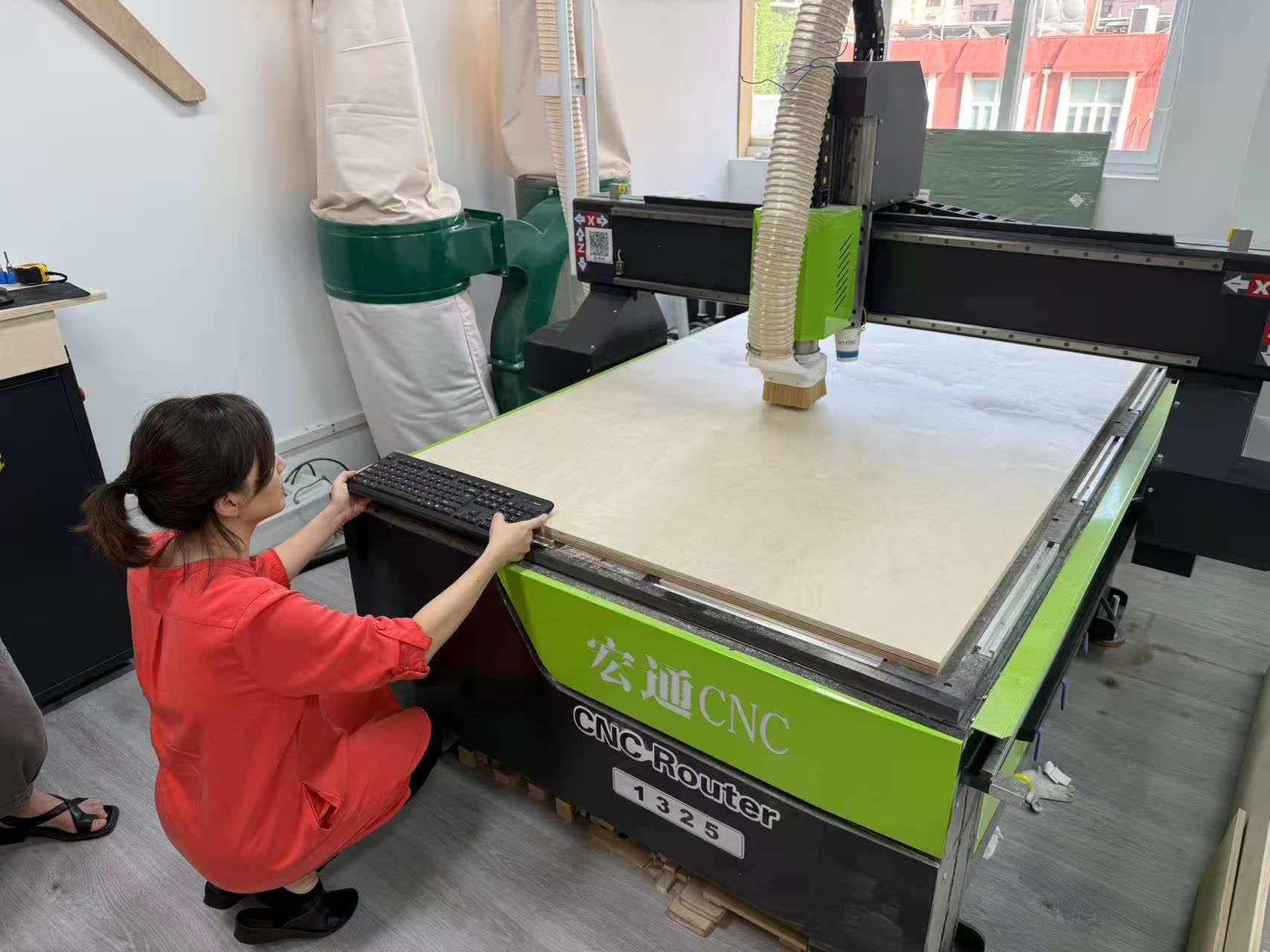 Our aim is to position the components towards the bottom-left corner.
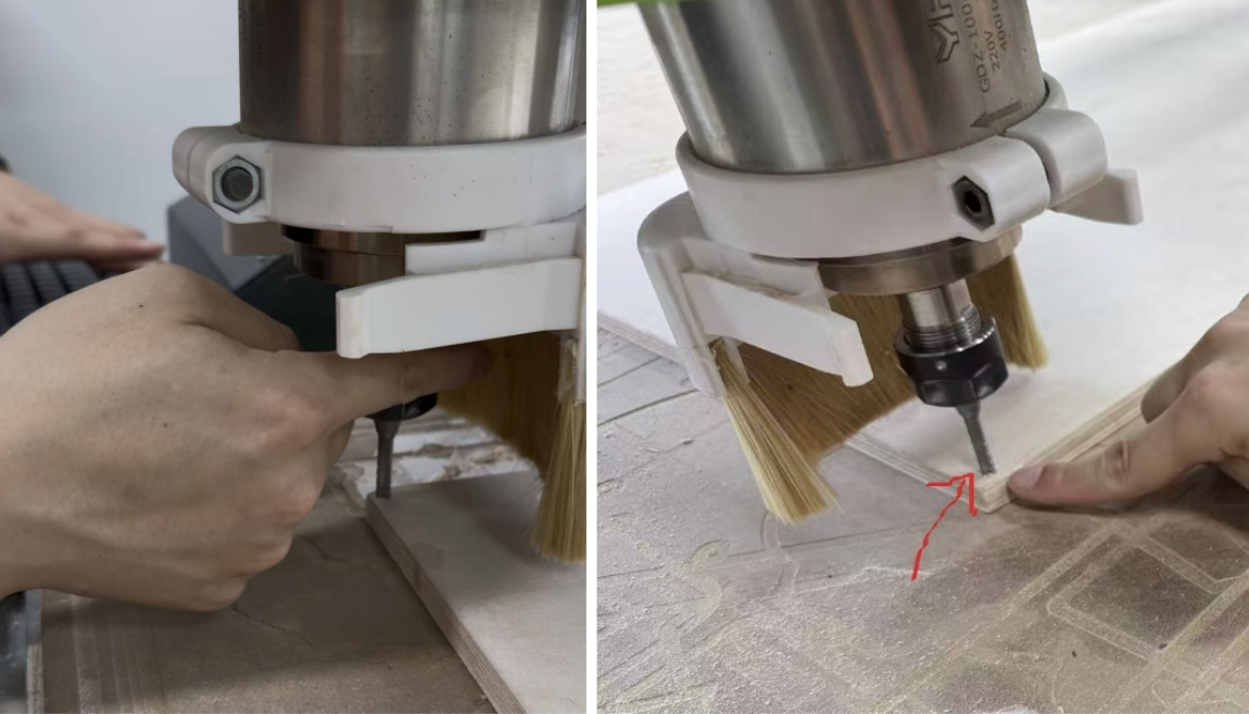
Machine Running
Post processing
The machine is running, and it takes several minutes to complete the process. Afterward, we obtained the cutting board, ready for assembly or further processing. 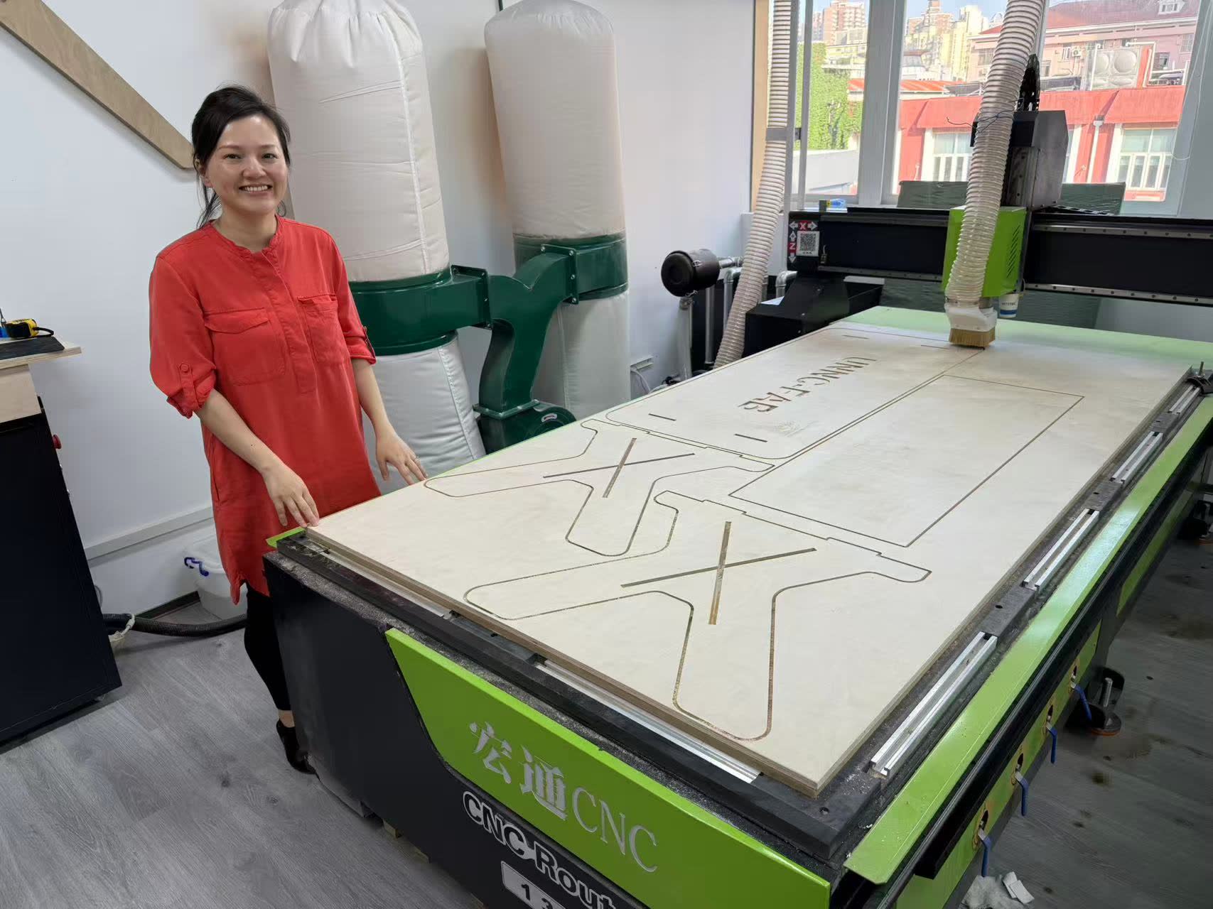 The following images show the board just taken out of the machine, ready for inspection and further use.
 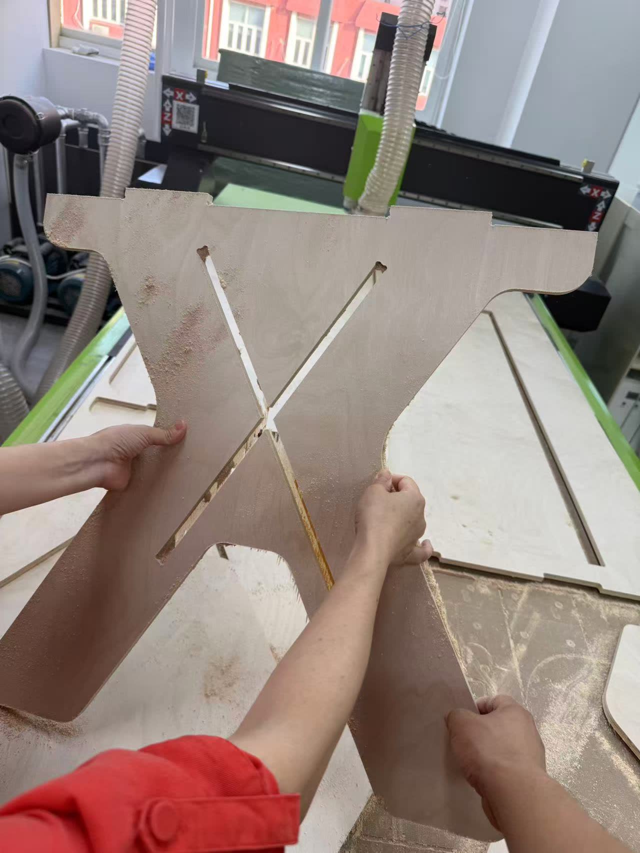 Use sandpaper to polish the board, smoothing out any rough edges or surfaces left from the cutting process.
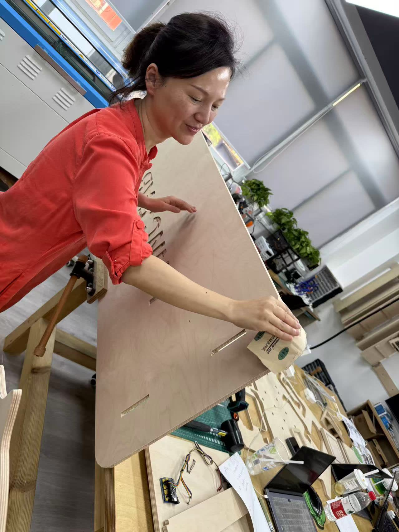
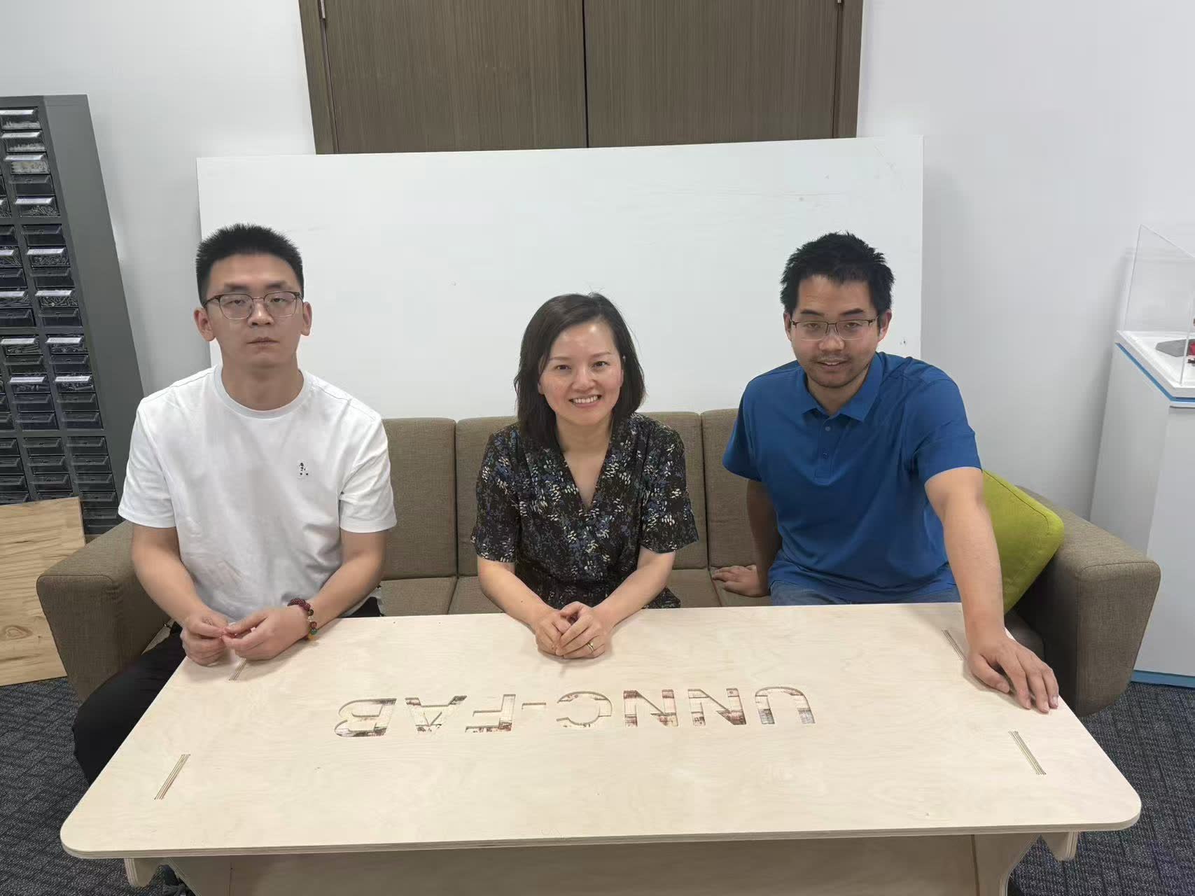
Result
Assemble it and we can use it as a table.