Appearance
Week 12 - Mechanical design, Machine design
Assignments
Group Assignment
- Design a machine that includes mechanism+actuation+automation+application
- Build the mechanical parts and operate it manually
- Document the group project and your individual contribution
Group WorkingOur group assignment focuses on designing and building a mechanical device capable of performing writing functions. I am primarily responsible for the structural design of the entire machine.
The mechanical structure adopts a gantry-style 3D printer architecture, known for its excellent stability and scalability. The X-axis utilizes a synchronous belt drive, offering high speed and responsive movement, making it well-suited for wide-range lateral motion. In contrast, the Y-axis and Z-axis employ screw drives, which provide high transmission precision—ideal for vertical and longitudinal movements that demand greater stability and positioning accuracy.
On the control side, the device operates using Marlin firmware, which is highly compatible and configurable. It effectively supports the parsing and motion control of G-code instructions. The drawing path is generated using Inkscape, with the aid of a dedicated plug-in for path conversion, allowing for intuitive and user-friendly operation. The resulting G-code is transmitted to the main control board via Repetier-Host software, enabling remote control and real-time monitoring of the device.
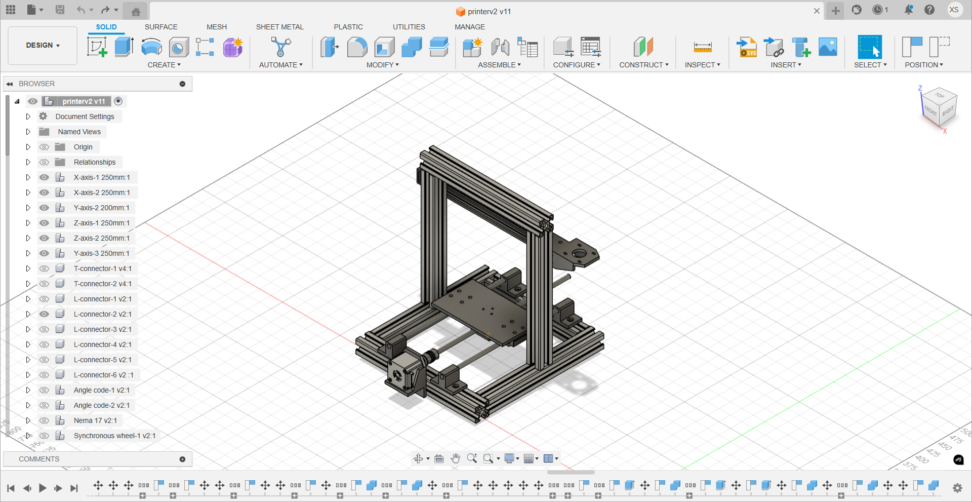
Machine Design in Fusion 360
I completed the device's exterior modeling using Fusion 360, with the design concept referencing the common CoreXY architecture. The framework is constructed with 3030 aluminum profiles to ensure mechanical stability and scalability.
Main tools and materials used:
- Main control board: Arduino Mega 2560
- Driver expansion board: RAMPS 1.4
- Stepper motors: 42 stepper motors × 4
- Stepper motor drivers: A4988 × 4
- Z-axis transmission structure:
- 2mm lead screws × 2
- Couplers (5mm to 8mm) × 2
- Aluminum profiles:
- 3030 aluminum profiles: 250mm × 6, 200mm × 2
- 2020 V-slot aluminum profiles: 300mm × 1
- Auxiliary components:
- Various 3D printed parts (such as slider brackets, belt clamps, etc.)
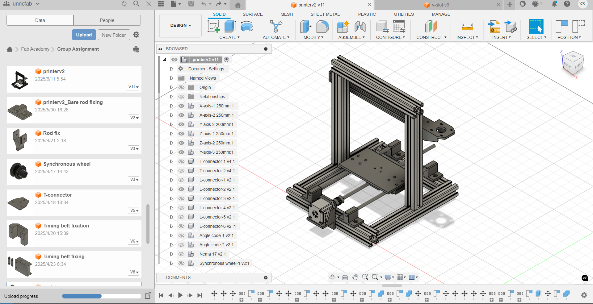
Here is the final version of the design in Fusion 360:
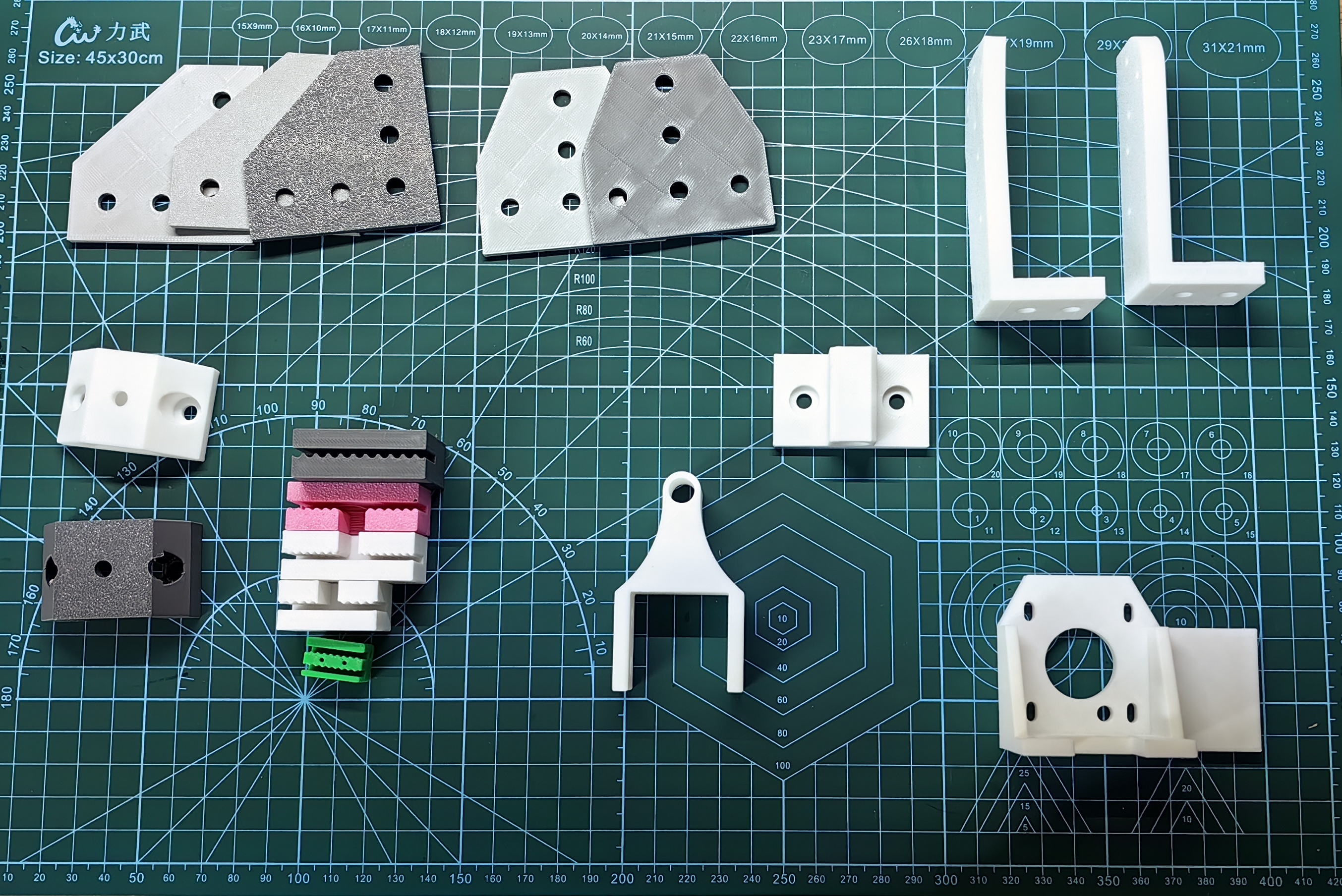
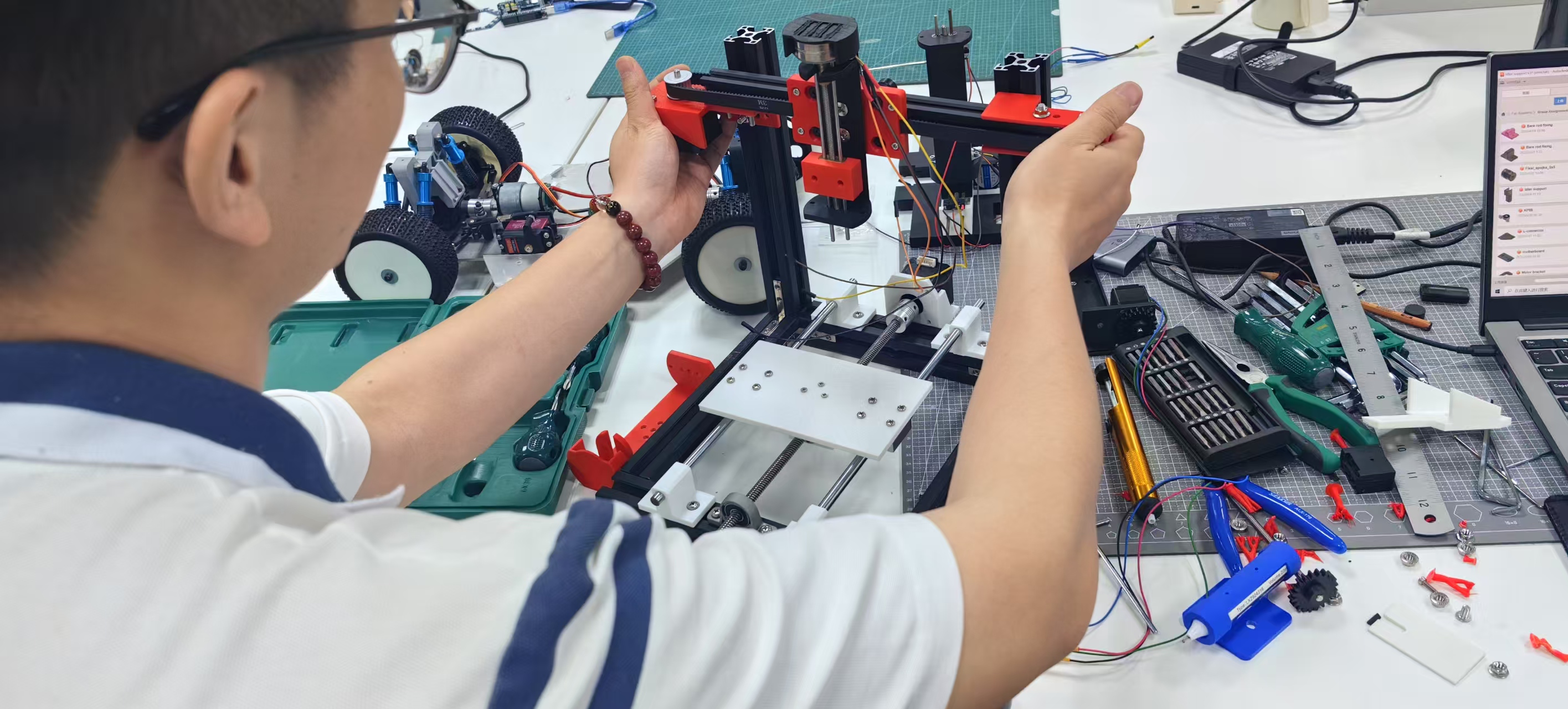
The following structural components are used in this design, including T-shaped brackets, L-shaped brackets, and various fasteners. Originally, all components were planned to be fixed using 3D-printed parts. However, testing revealed that the fixation was not satisfactory. Therefore, the aluminum profile frame has been modified to use standard hardware for connections and fixation. For special structures where standard parts cannot be used, 3D-printed components will continue to be used for auxiliary support.
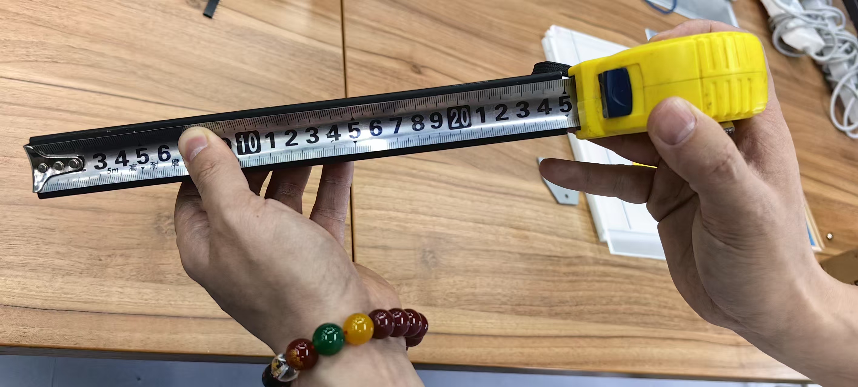
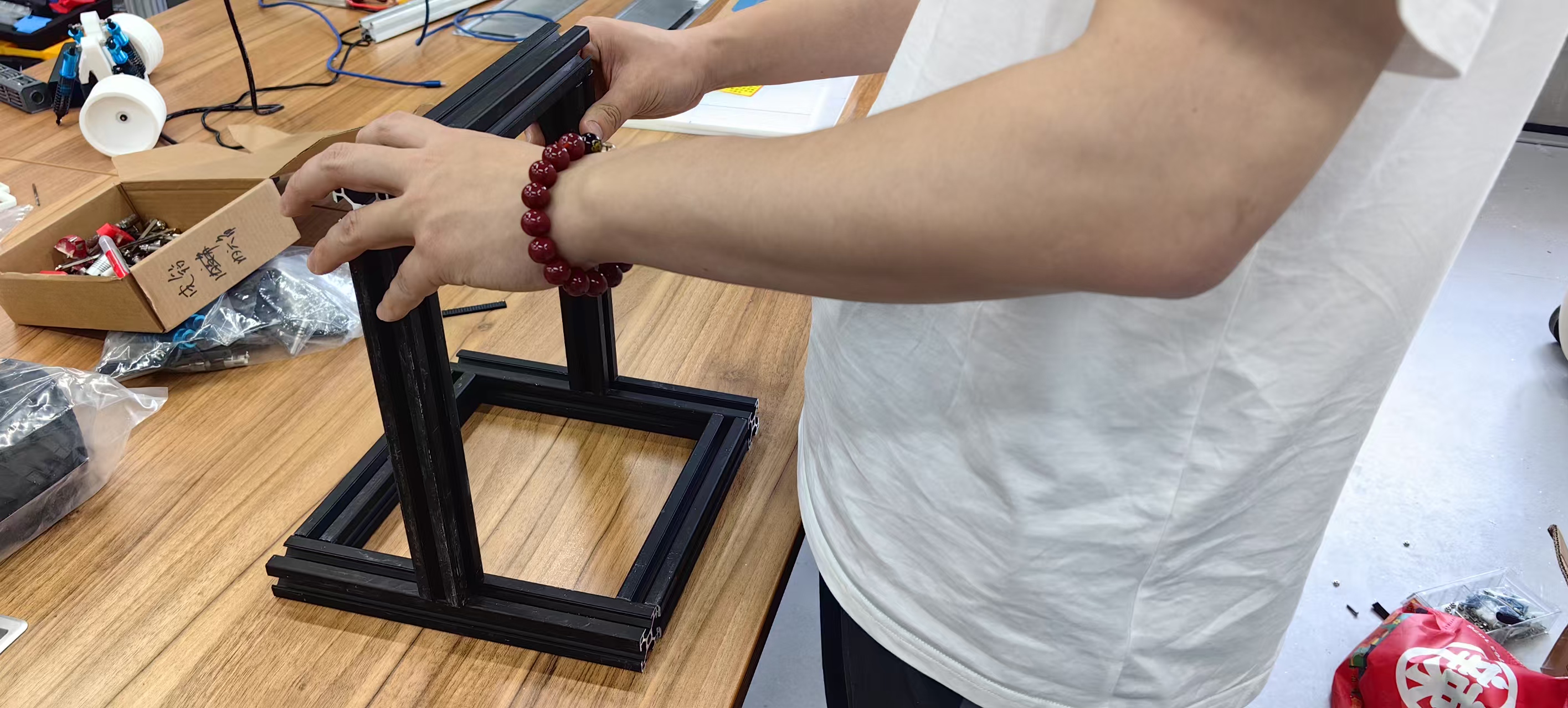
Aluminium Profile Preparation
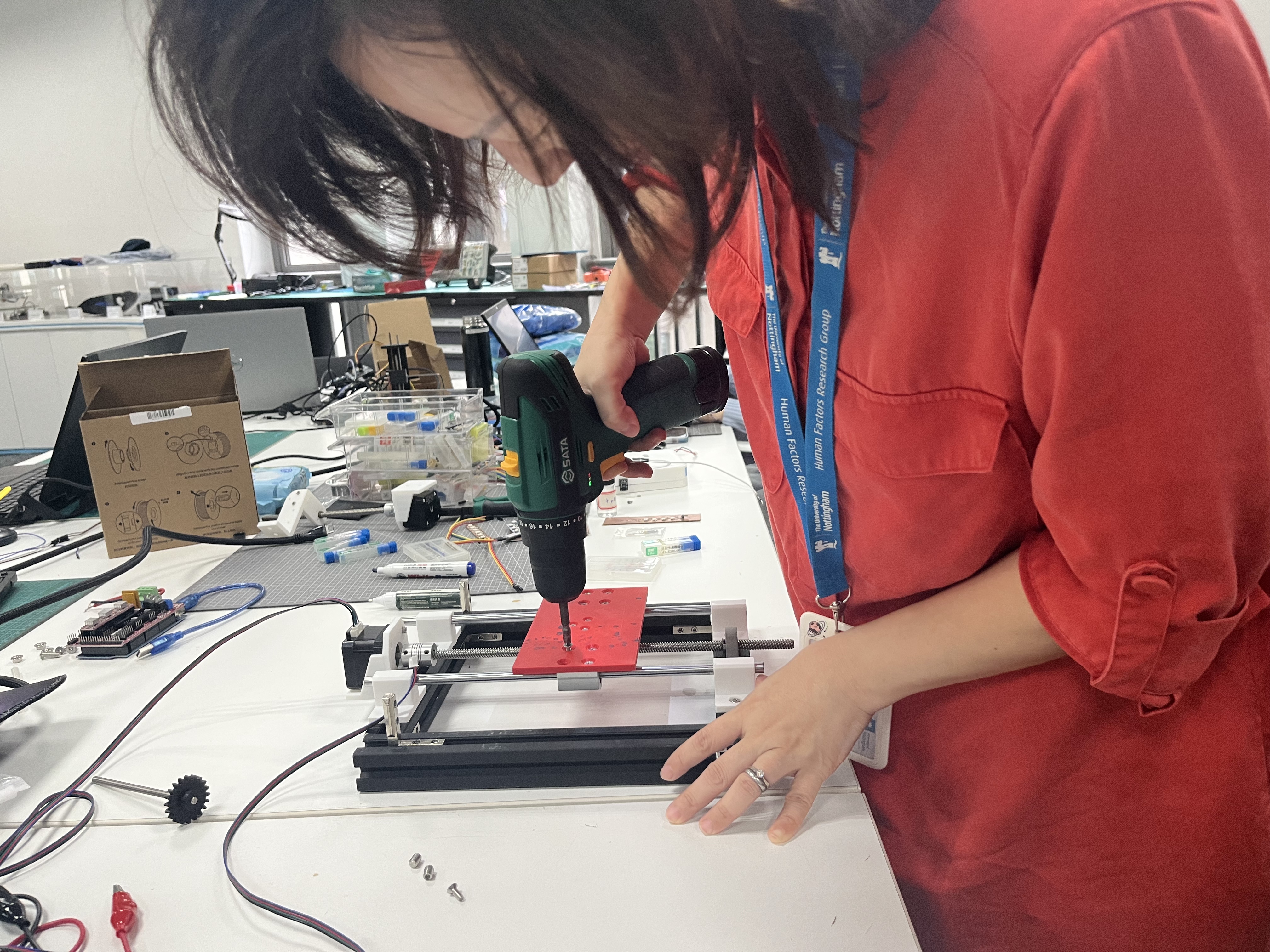
Based on the completed 3D model design, my teammate Yaorun Zhang and I jointly completed the aluminum profile processing work. We used measuring tapes to determine required dimensions and performed the cutting operations using a cutting machine. 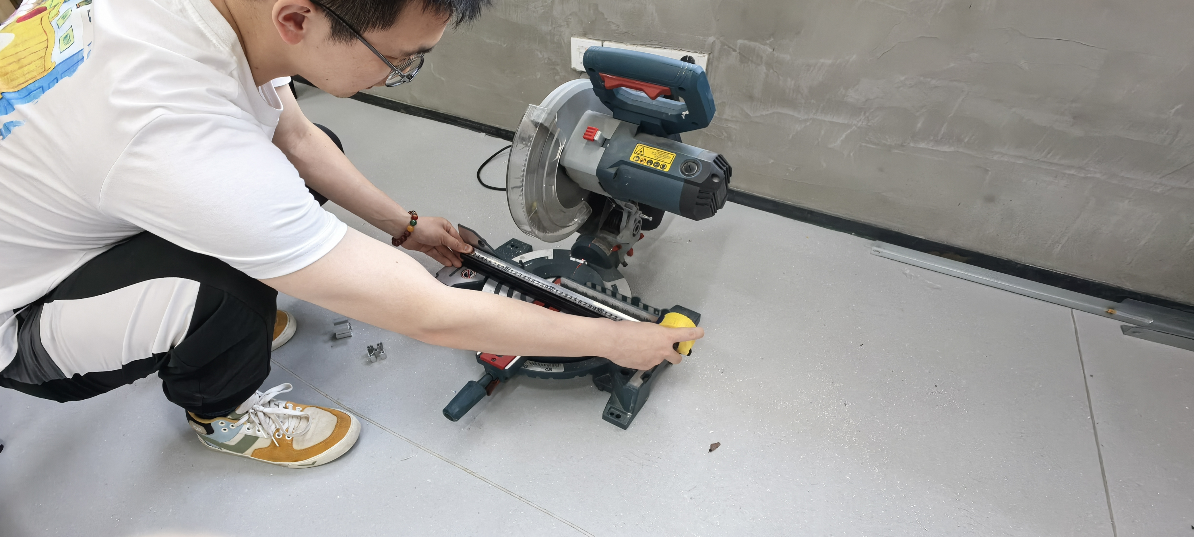
- Aluminum profile assembly
3D Printing
Here are some of the 3D printed components, including T-shaped and L-shaped brackets, whose mounting performance proved unsatisfactory, leading us to ultimately adopt standard hardware. For the timing belt fasteners, we designed several gear-clip structures, but during operation we observed belt slippage, prompting us to switch to screw-based fastening instead.
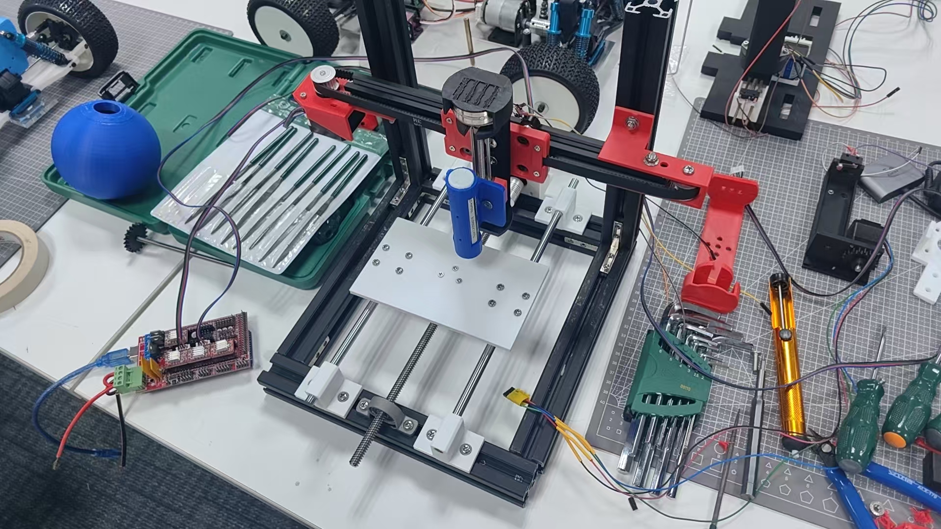
Assembled Printer Structure
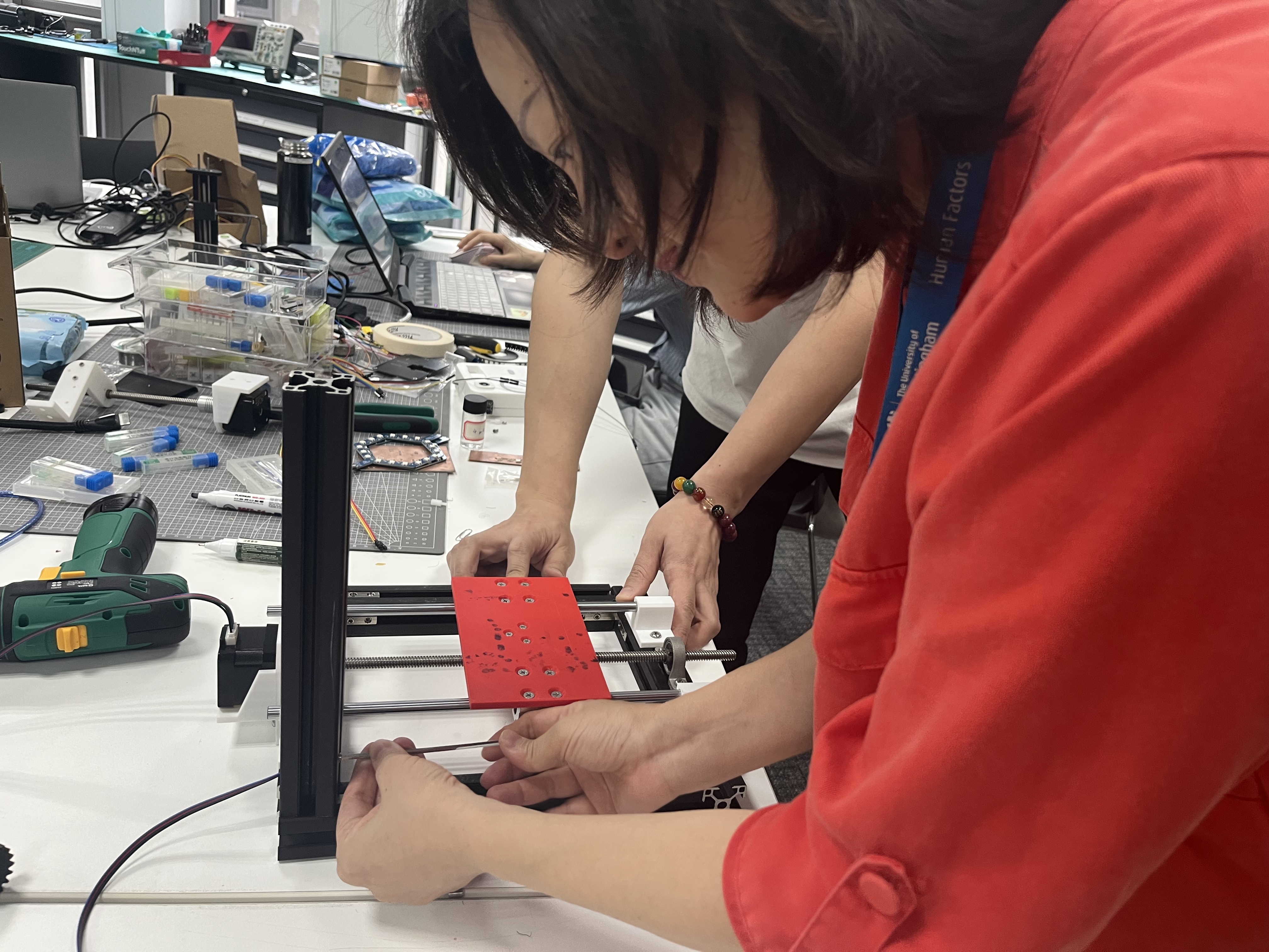
Software Debugging
Marlin Firmware
The software side utilizes Marlin firmware, which is flashed using Arduino IDE and debugged with a serial port assistant. Here's an introduction to Marlin firmware:
- Marlin firmware is an open-source 3D printer project from the RepRap series. It originated from the open-source Sprinter and grbl projects, becoming an independent open-source project on August 12, 2011, freely available to everyone. Using Marlin firmware allows customization of 3D printers (for functions like laser engraving, writing, CNC, etc.), with the firmware providing corresponding configuration interfaces for these features.
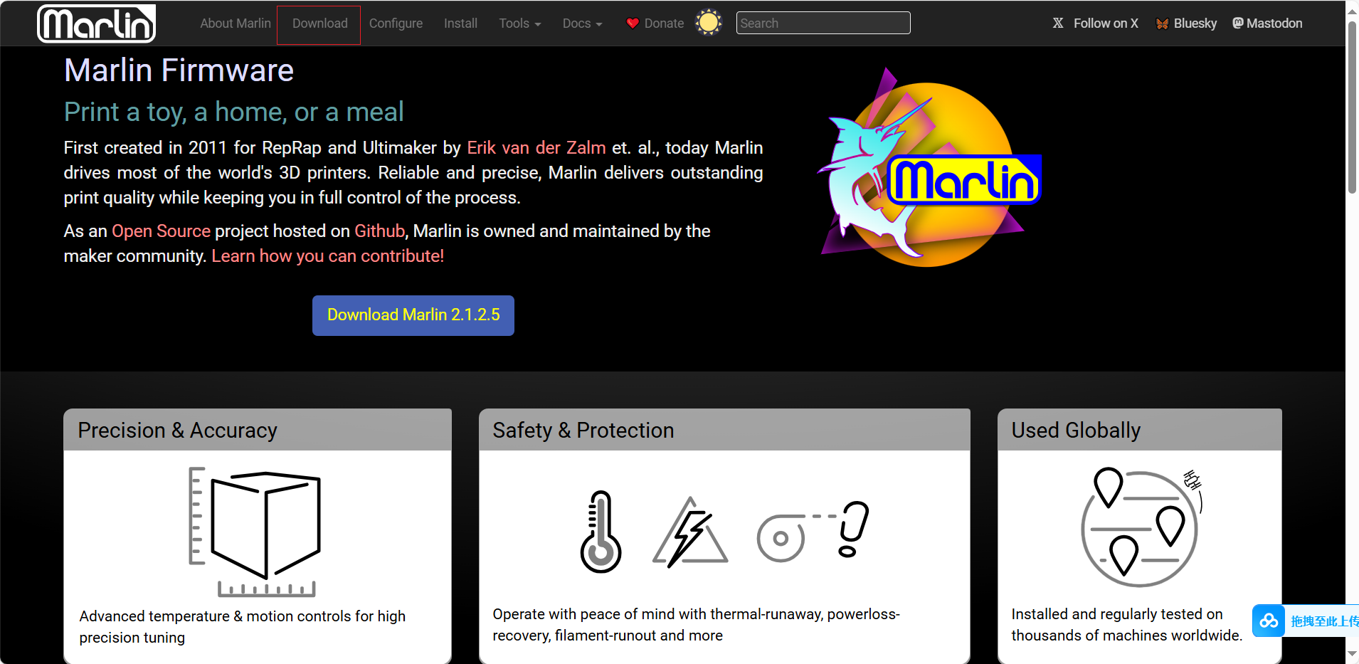
Visit the Marlin official website and click Download
Here I selected the current Marlin version, downloaded and extracted it
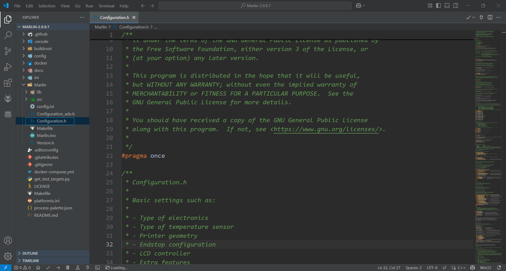
When configuring Marlin firmware, only a few configuration files need to be modified:
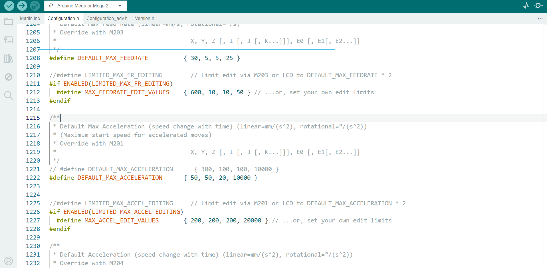
Configuration.h: Contains core settings for hardware, language and controller selection, as well as settings for the most common features and components.
Configuration_adv.h: Provides more detailed customization options, add-ons, experimental features and other deeper-level settings.
Marlin firmware configuration mainly includes the following aspects:
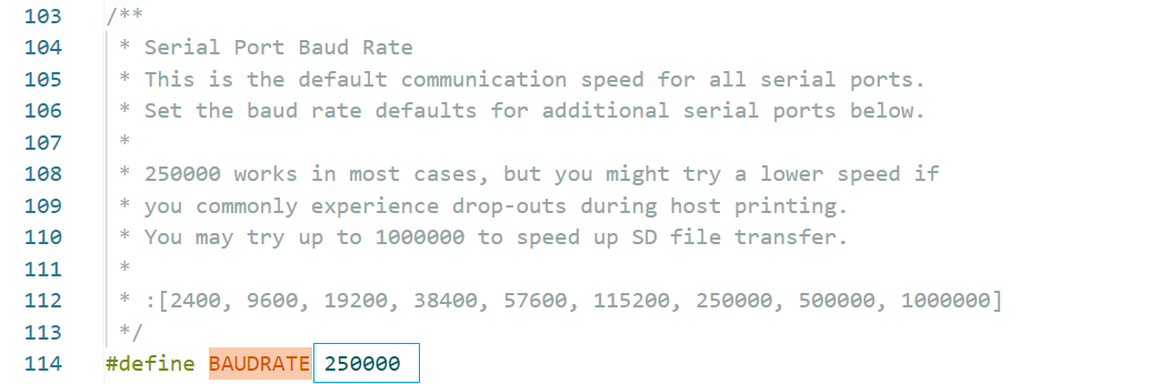
- Communication baud rate
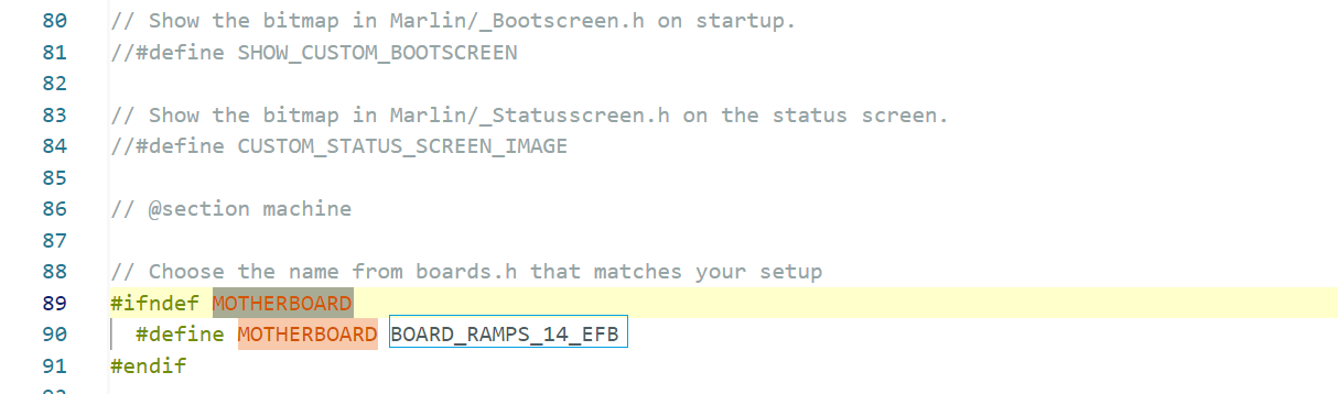
- Mainboard type (the specific board being used)
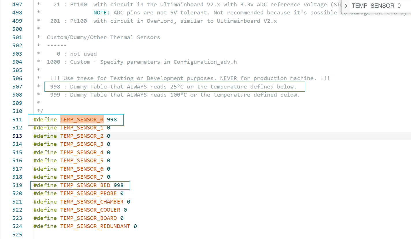
- Temperature sensor types (including extruder thermistor and heated bed thermistor)
- Temperature settings (including nozzle temperature and bed temperature)
- PID temperature control parameters (for both nozzle and bed temperature control)
- Endstop switches
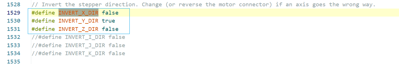
- Stepper motor directions for all 4 axes
- Initial positions for X/Y/Z axes
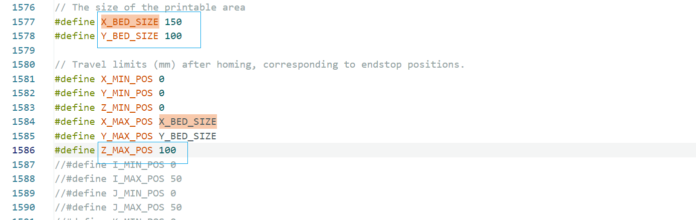
- Printer movement range
- Auto bed leveling
- Movement speeds
- Axis movement resolution
- Standalone controller
Before configuration, I need to confirm some information. We are using RAMPS 1.4 + Mega2560, with temperature control disabled, endstops disabled, LCD disabled. Step distance and direction will be calibrated via G-code, with full manual control: We can send G0 or G1 commands through serial port to control motor movement. Now let's begin the configuration:
Communication Baud Rate
Mainboard Type
- Compatible with RAMPS 1.4 + Mega2560, using 4 stepper interfaces (X/Y/Z/E0)
- Temperature Sensor Type
- Since no temperature sensors are connected, using virtual sensors to bypass thermal protection
- Temperature Configuration
- The heating function is not used and can be skipped. With virtual sensors, Marlin bypasses temperature checks and allows motor operation directly
- PID Temperature Control Parameters
- No hotend/heated bed used, no need to set PID parameters. Marlin will ignore PID control by default
- Endstop Switches
- Not using endstop switches, can be skipped
- Stepper Motor Directions
- Using default directions
- X/Y/Z Initial Positions
- Without endstops, we'll make it "pretend" to be ready at origin. Home command won't perform actual movement.
- Printer Movement Range
- XY area: 150mm x 100mm, Z-axis set to 50mm
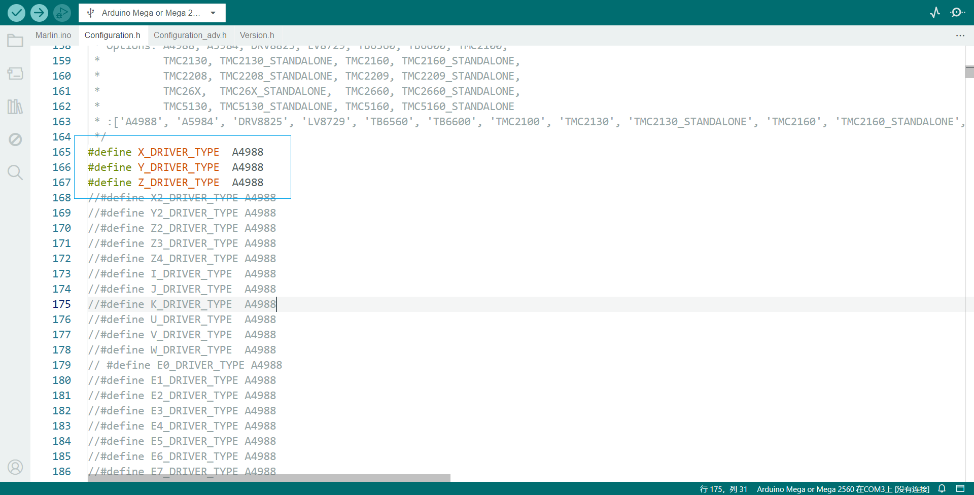
- Motor Drivers
- X, Y, Z motor drivers all set to A4988. Enabled second Z-axis motor (Z2), connected to Z2 driver (usually connected to E1 interface). Although extrusion function isn't used, Marlin requires definition - E0 interface can be left as default.
Next, it is necessary to configure the maximum movement speed and maximum acceleration of the motors. After multiple rounds of testing and adjustments, the following parameters were determined to be the most suitable for the current mechanical structure and operational requirements.
- After configuring the parameters, upload the firmware to the main control board. Once the upload is successful, you can send G-code commands via the serial port for debugging. At this stage, it is important to be familiar with some commonly used basic G-code commands.
Debugging commands:
- Control the device to move to the set origin position
G28- Set the current position to the specified coordinates
G92 X0 Y0 Z0- Move to the specified coordinate point in a straight line at the set speed
G1 X10 Y10 Z10Gcode Generation
Inkscape + G-code Plug-in
We use Inkscape combined with the G-code plug-in to export vector paths to G-code. The process is as follows:
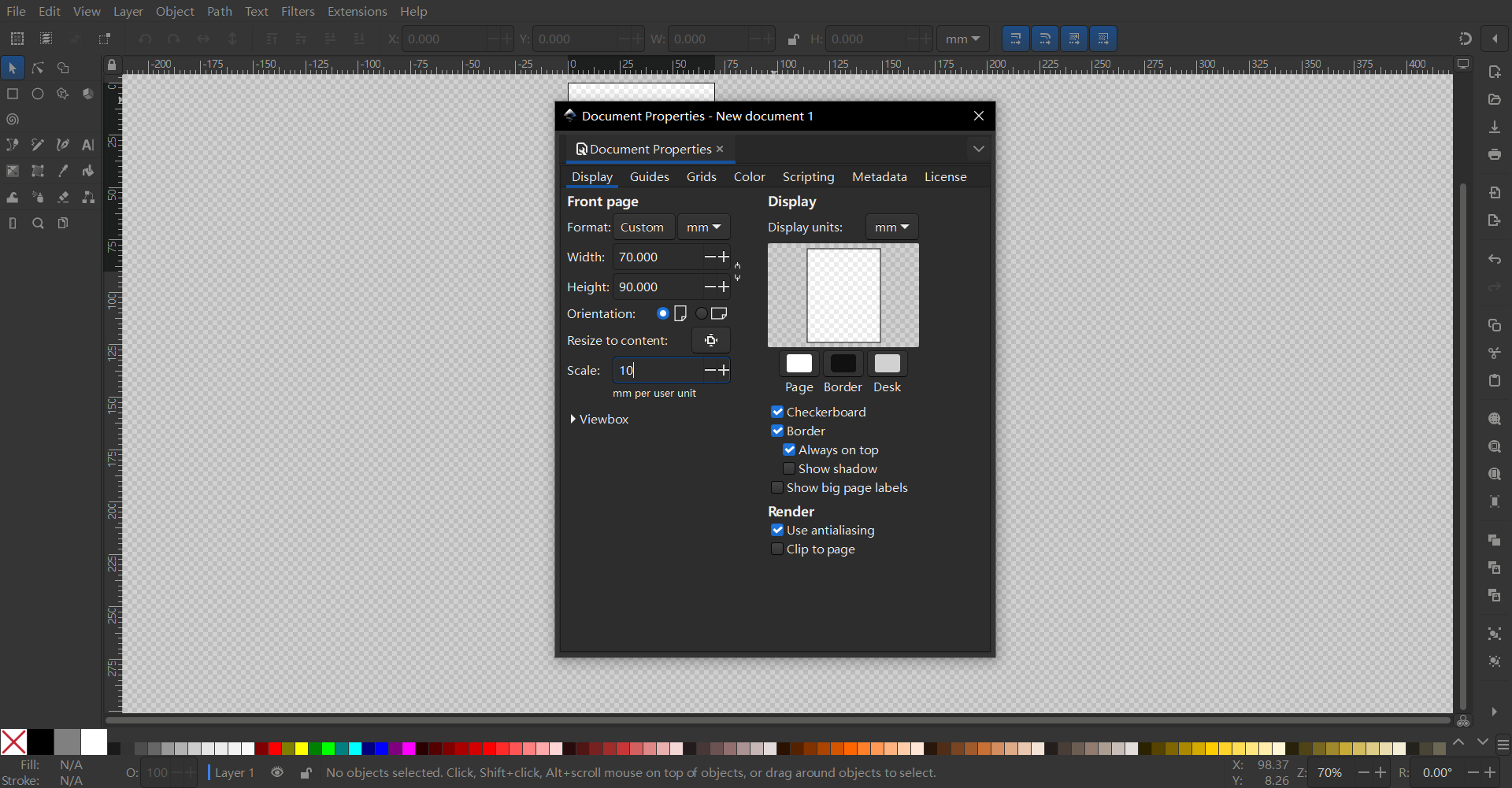
First set the canvas size to 70x90:
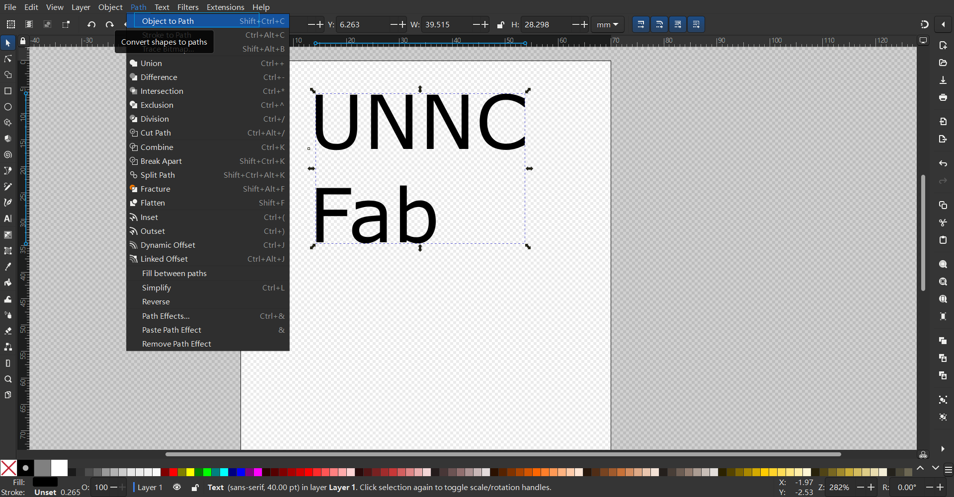
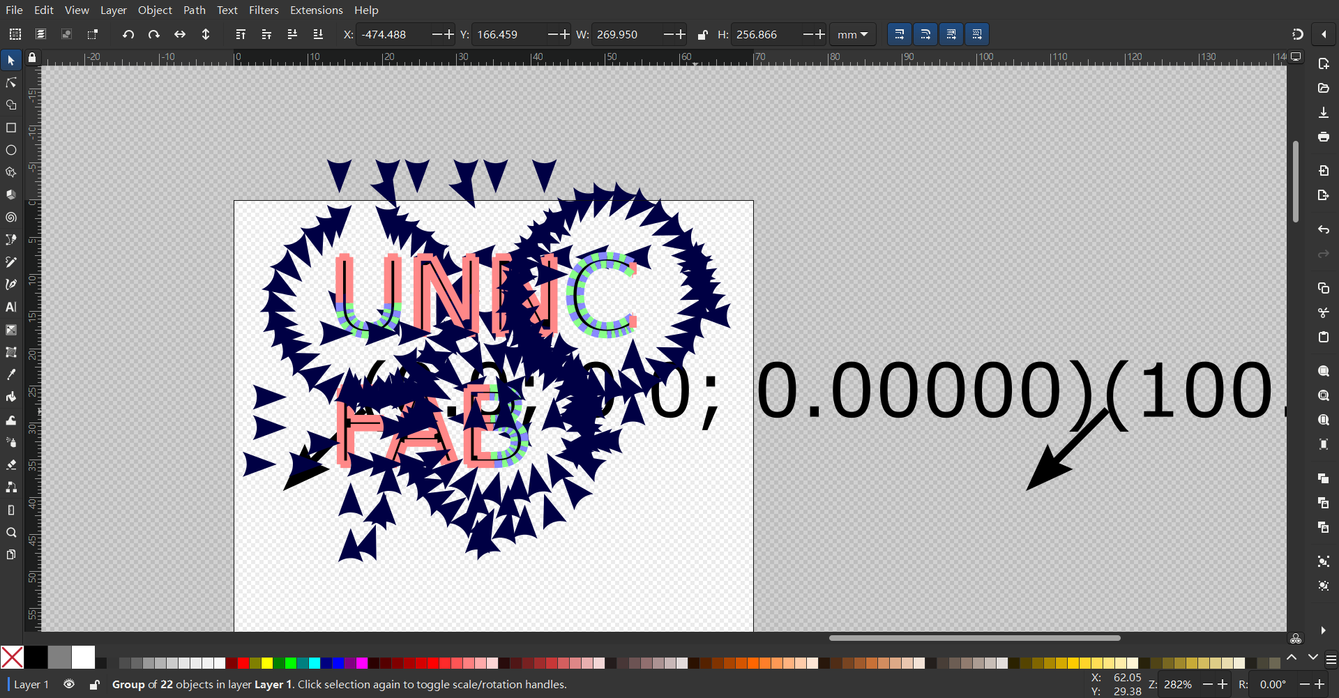
Enter the text we need to draw in Inkscape and convert it into a path
Select the path and choose Convert Object to Path
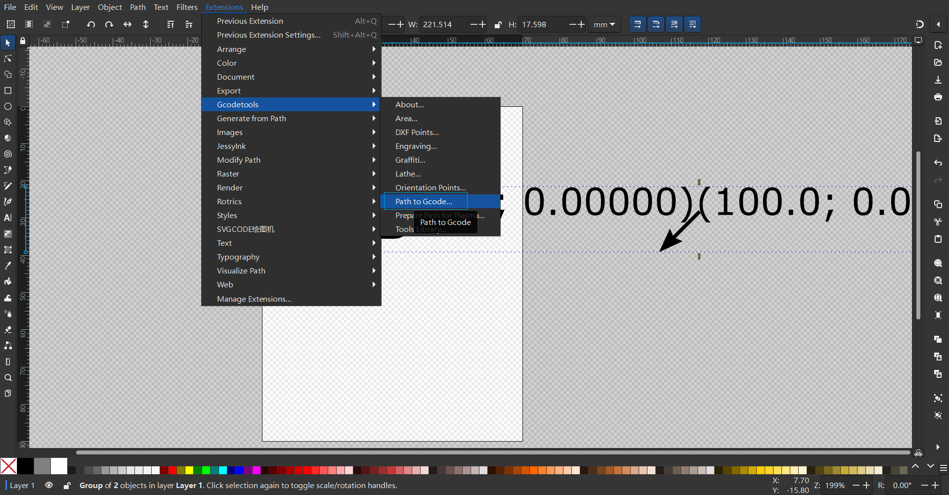
Click Extensions, select GcodeTools, then select Orientation Points
 Select Apply
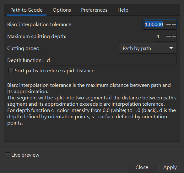
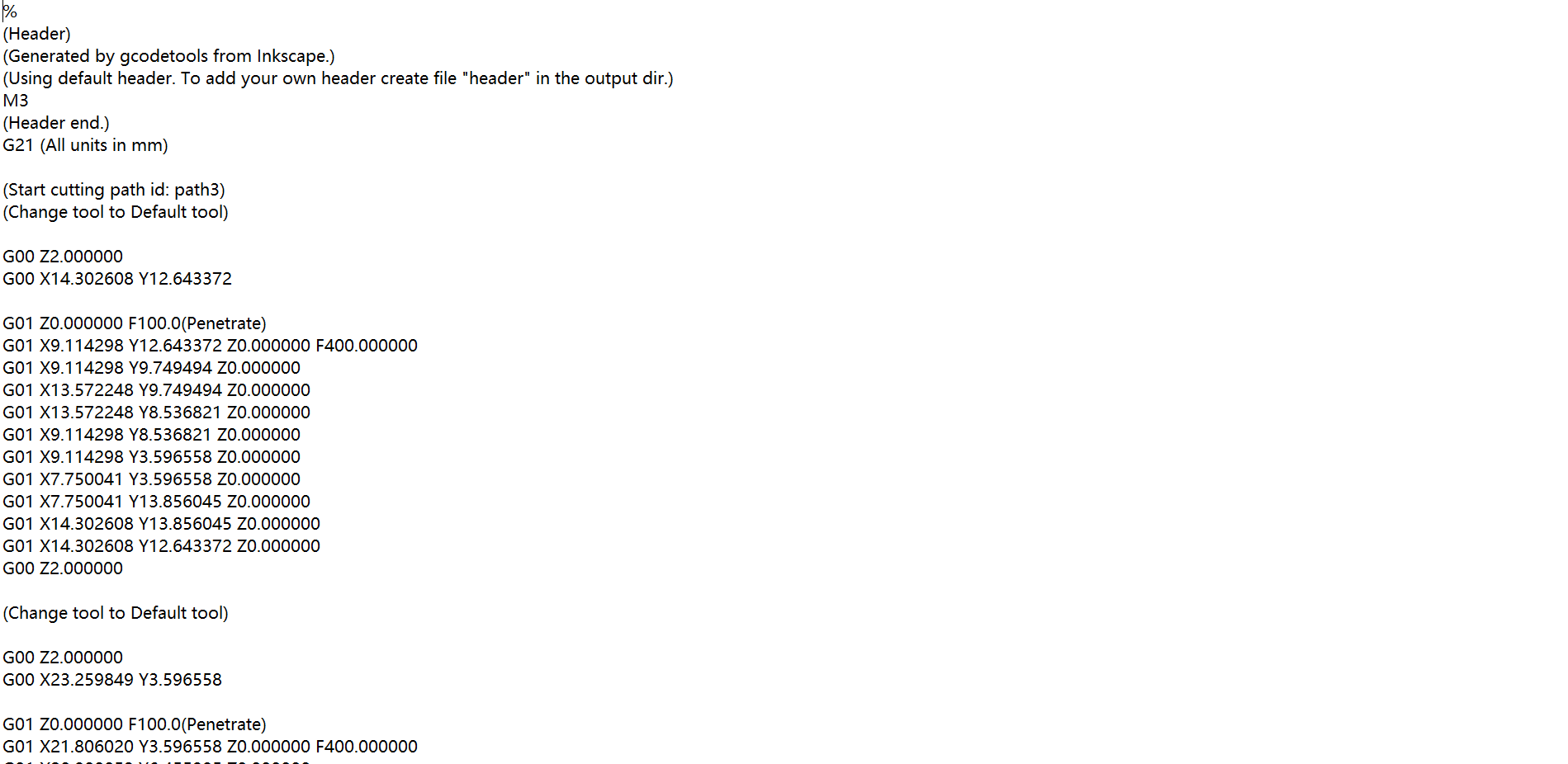
Generate the path and get the .gcode file, then send it to the control board for execution through Repetier-Host.
- Connect the printer, load the generated .gcode file, and start printing
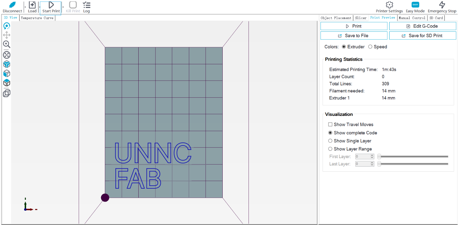 Final result:
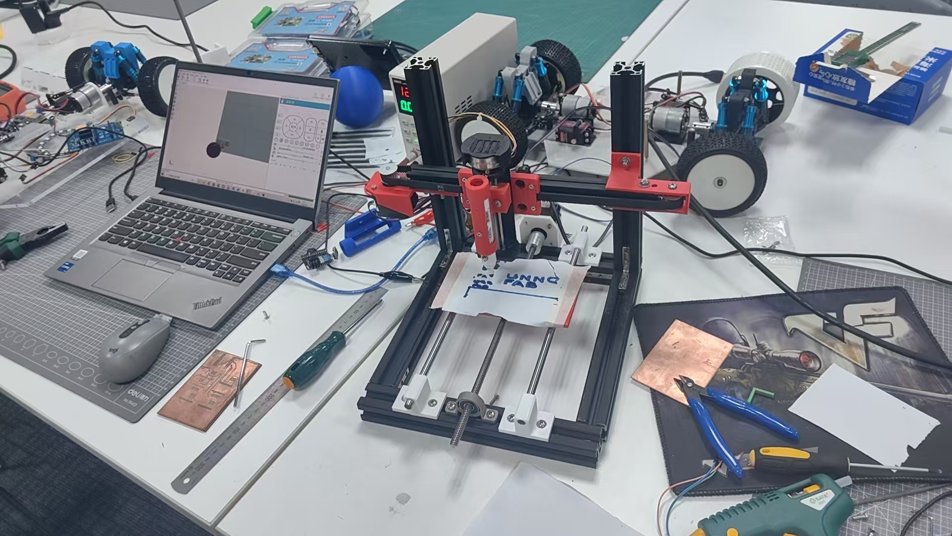
Reference
- The design files can be found in my repository:https://gitlab.fabcloud.org/academany/fabacademy/2025/labs/unnc/students/xu-sun/-/blob/main/docs/assignments/week12/resource-week12/printerv2+v12.f3z?ref_type=heads