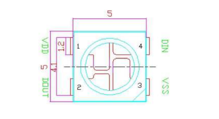
Appearance
Week 10 - Output Devices
Assignments
Group Assignment
- Measure the power consumption of an output device
Individual Assignment
- Add an output device to a microcontroller board you've designed, and program it to do something
Group Working
My group work is attached here: https://fabacademy.org/2025/labs/unnc/assignments/week9/week09.html
Individual Working
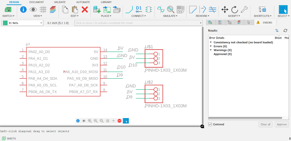
This week's assignment involves designing a simple PCB using Fusion 360 to test output devices such as servos and WS2812 LEDs. The PCB will then be processed using the Roland EGX-300
Fusion 360 Design
- Schematic:
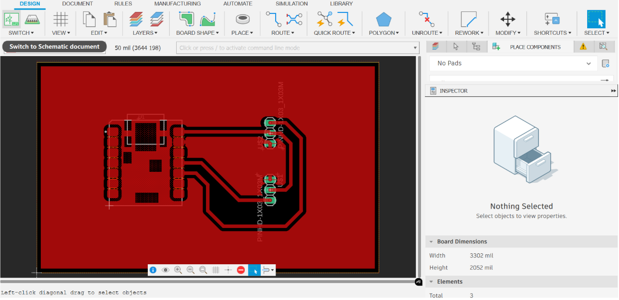
 2. PCB Document:
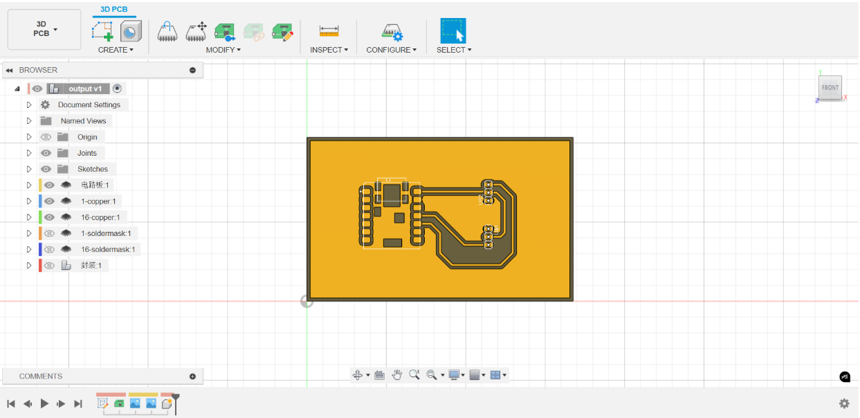
 3. 3D PCB:
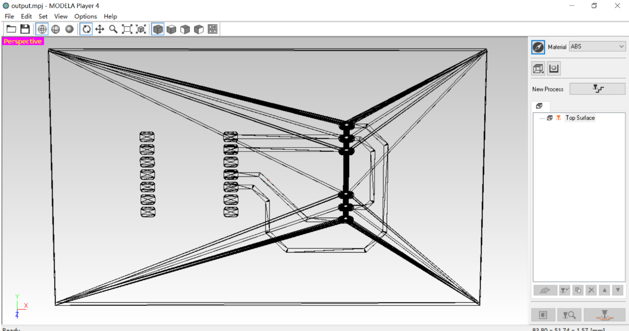
Manufacturing
- Import .stl file
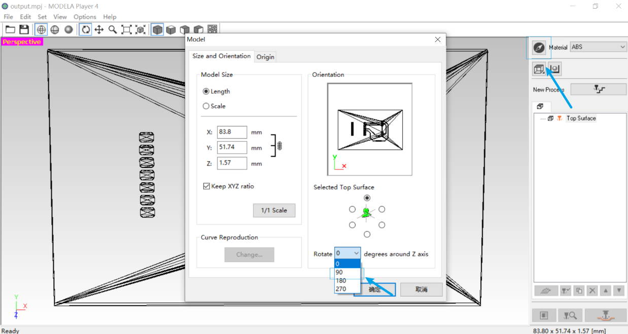
 2. Use the model function to rotate the angle by 90° to facilitate subsequent processing.
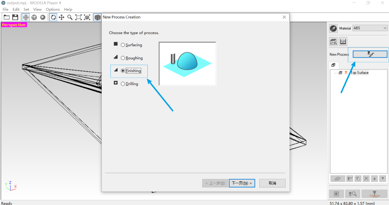
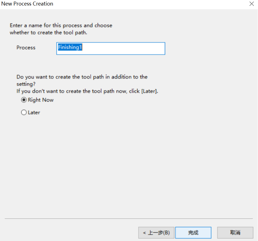
 3. Choose the type of process finishing
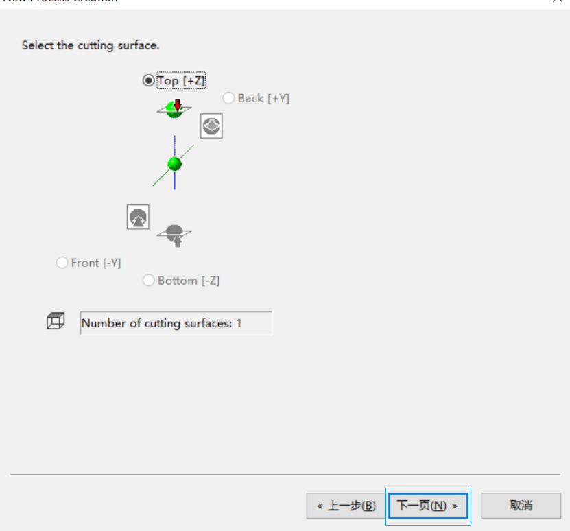
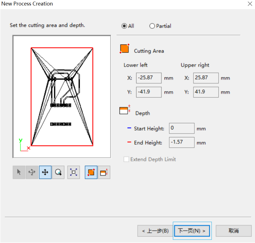
 4. Select cutting surface
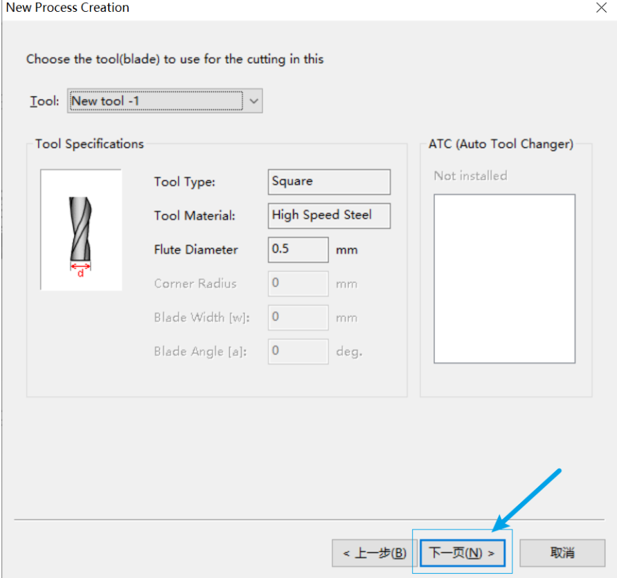
 5. Use a 0.5mm milling cutter
 6. Use the default processing area.
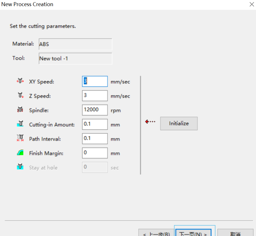
 7. Select and create the machining path type contour pitch.
8. Set the XY speed to 3mm/sec
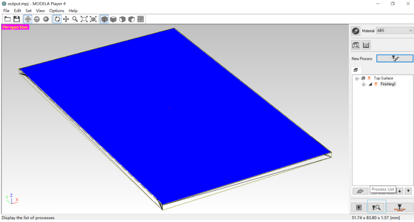
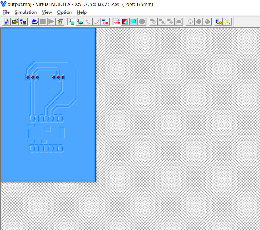
 9. Generate toolpath
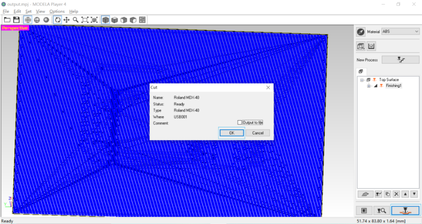
 10. Connect the computer to the Roland device and start uploading.
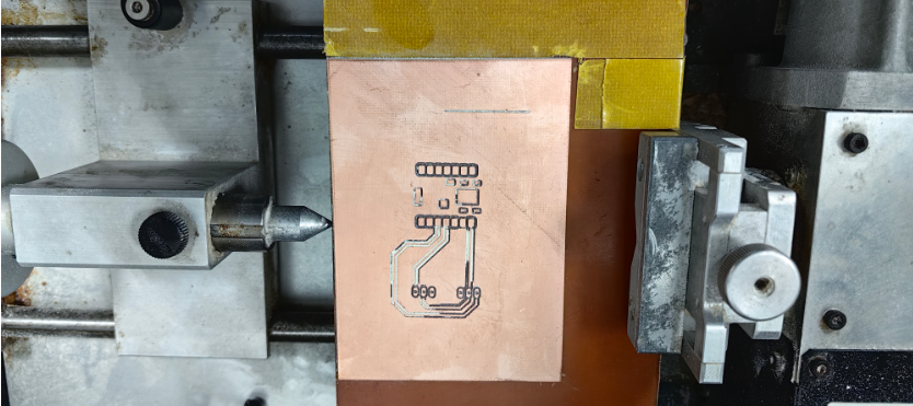
 11. Start machining
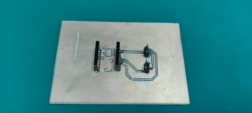
- The picture after completing the machining.
- The machined PCB has some issues where the holes and traces are not properly connected, although simulations indicate that these parts should be connected. It is speculated that this may be due to the use of an oversized milling cutter diameter or incorrect parameter settings. To verify and resolve this issue, we plan to attempt machining with a 0.2mm milling cutter.
 13. Picture after soldering completion
Functional Testing:
- Use XIAO ESP32 C3 to control WS2812 color change.
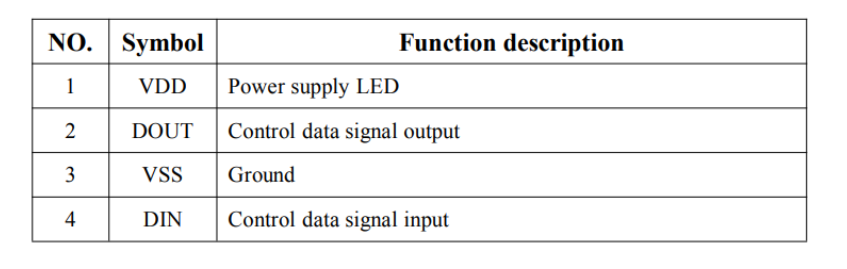
- PIN configuration
- PIN function
- Add the Adafruit_NeoPixel.h library.
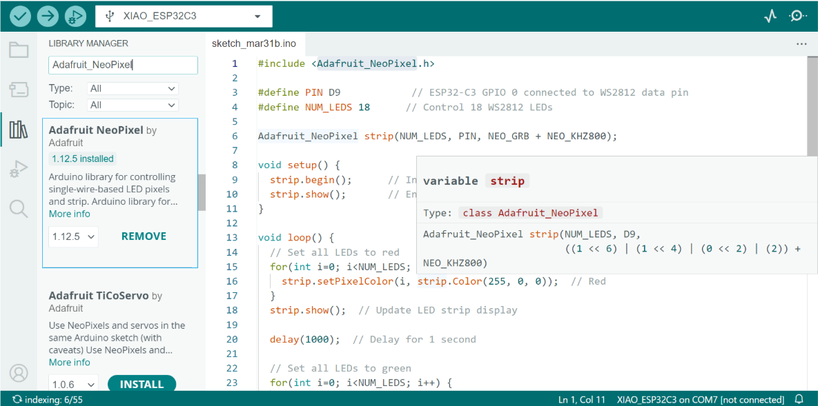
- The control code for the WS2812 LEDs is as follows:
cpp
#include <Adafruit_NeoPixel.h>
#define PIN D9 // ESP32-C3 GPIO 0 connected to WS2812 data pin
#define NUM_LEDS 18 // Control 18 WS2812 LEDs
Adafruit_NeoPixel strip(NUM_LEDS, PIN, NEO_GRB + NEO_KHZ800);
void setup() {
strip.begin(); // Initialize the NeoPixel strip
strip.show(); // Ensure all LEDs are off at startup
}
void loop() {
// Set all LEDs to red
for(int i=0; i<NUM_LEDS; i++) {
strip.setPixelColor(i, strip.Color(255, 0, 0)); // Red
}
strip.show(); // Update LED strip display
delay(1000); // Delay for 1 second
// Set all LEDs to green
for(int i=0; i<NUM_LEDS; i++) {
strip.setPixelColor(i, strip.Color(0, 255, 0)); // Green
}
strip.show(); // Update LED strip display
delay(1000); // Delay for 1 second
// Set all LEDs to blue
for(int i=0; i<NUM_LEDS; i++) {
strip.setPixelColor(i, strip.Color(0, 0, 255)); // Blue
}
strip.show(); // Update LED strip display
delay(1000); // Delay for 1 second
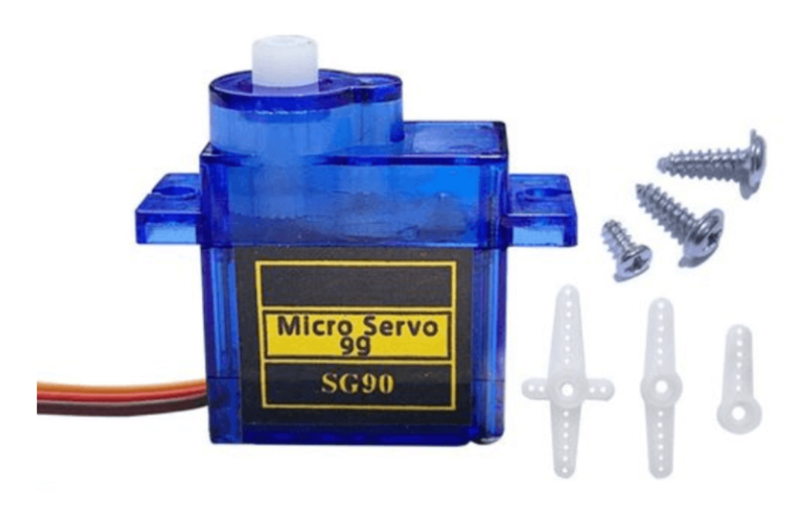
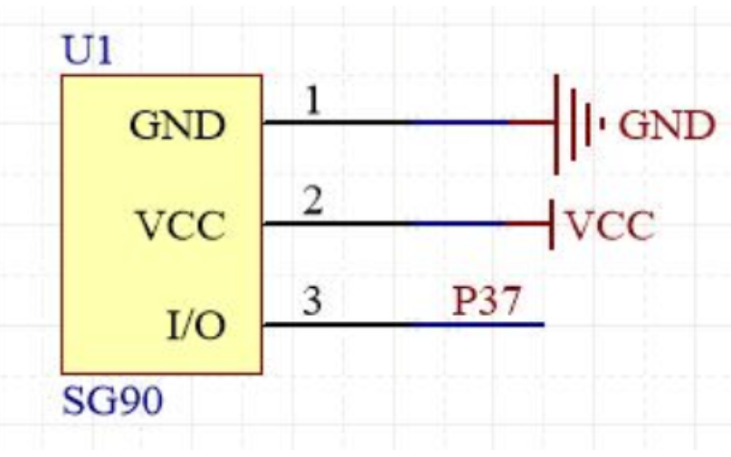
}- Use XIAO ESP32 C3 to control servo motor movement.
- Servo model: SG90
- Schematic Diagram
- The rotation angle of the servo is achieved by adjusting the duty cycle of the PWM signal. The standard PWM signal has a fixed period of 20ms, with pulse widths typically ranging from 0.5ms to 2.5ms, corresponding to a rotation angle range of 0° to 180°.
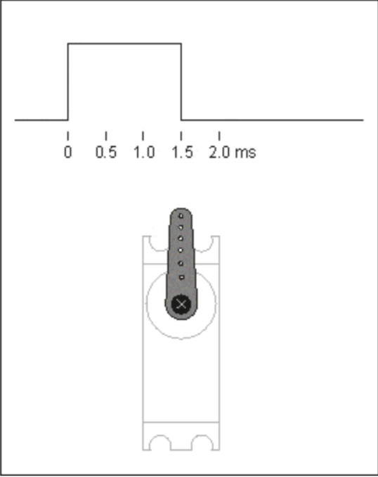
- When the servo motor moves back and forth between 0° and 180°, the following demonstrates the operational effect.
- Test Code
cpp
#include <ESP32Servo.h>  // Use the ESP32Servo library

Servo myservo;  // Create a Servo object to control a servo motor

#define SERVO_PIN D10  // Set the pin to control the servo, connected to D10

void setup() {
  myservo.attach(SERVO_PIN);  // Attach the servo to the specified pin
  Serial.begin(115200);  // Initialize serial communication for debugging
}

void loop() {
  // Move the servo from 0 degrees to 180 degrees
  for (int pos = 0; pos <= 180; pos++) {
    myservo.write(pos);  // Move the servo to the specified angle
    delay(15);           // Delay 15 milliseconds to ensure smooth motion
  }

  delay(1000);  // Pause for 1 second

  // Move the servo back from 180 degrees to 0 degrees
  for (int pos = 180; pos >= 0; pos--) {
    myservo.write(pos);  // Move the servo to the specified angle
    delay(15);           // Delay 15 milliseconds to ensure smooth motion
  }

  delay(1000);  // Pause for 1 second
}
Reference:
The reference and design files are listed below:
The .3mf file for the PCB is available in my respository:https://gitlab.fabcloud.org/academany/fabacademy/2025/labs/unnc/students/xu-sun/-/blob/main/docs/assignments/week10/resource-week10/week10-pcbboard.3mf?ref_type=heads
The toolpath files for CNC machining are available in my repository:https://gitlab.fabcloud.org/academany/fabacademy/2025/labs/unnc/students/xu-sun/-/blob/main/docs/assignments/week10/resource-week10/week10-cnc.mpj?ref_type=heads
The .ino code file for the WS2812 is available in my repository:https://gitlab.fabcloud.org/academany/fabacademy/2025/labs/unnc/students/xu-sun/-/blob/main/docs/assignments/week10/resource-week10/week10-ws2813Demo.ino?ref_type=heads
The .ino code file for the servo is available in my repository:https://gitlab.fabcloud.org/academany/fabacademy/2025/labs/unnc/students/xu-sun/-/blob/main/docs/assignments/week10/resource-week10/week10-servoDemo.ino?ref_type=heads