Individual assignments
For Wildcard Week, I chose CAM-based metal laser cutting because I was particularly interested in learning how to fabricate metal parts using computer-aided manufacturing tools. My goal was to understand the workflow of converting a digital design into precise metal cuts. This process included preparing designs in CAD software, generating toolpaths in CAM, and executing the cutting using a metal laser cutter. It gave me hands-on experience with material-specific settings, safety protocols, and the technical capabilities of high-precision metal cutting systems.
Computer-Aided Manufacturing (CAM) refers to the use of software and computer-controlled machinery to automate the manufacturing process. CAM systems take digital designs created using Computer-Aided Design (CAD) software and generate toolpaths and machine instructions to control tools such as CNC mills, laser cutters, and 3D printers.
CAM enhances precision, reduces human error, and allows for complex geometries to be produced efficiently.
It plays a vital role in modern manufacturing by enabling rapid prototyping, mass production, and customization with high accuracy and repeatability. CAM is widely used in industries such as automotive, aerospace, electronics, and metal fabrication.
Metal laser cutting is a precise and efficient manufacturing process that uses a high-powered laser beam to cut through various types of metal sheets, such as steel, aluminum, or brass. This non-contact method produces clean edges and allows for intricate designs with minimal material waste. It is widely used in industries like automotive, aerospace, and fabrication for its accuracy, repeatability, and speed. The laser melts, burns, or vaporizes the material along a pre-defined path, controlled by computer-aided design (CAD) files. Metal laser cutting is ideal for both prototyping and mass production.
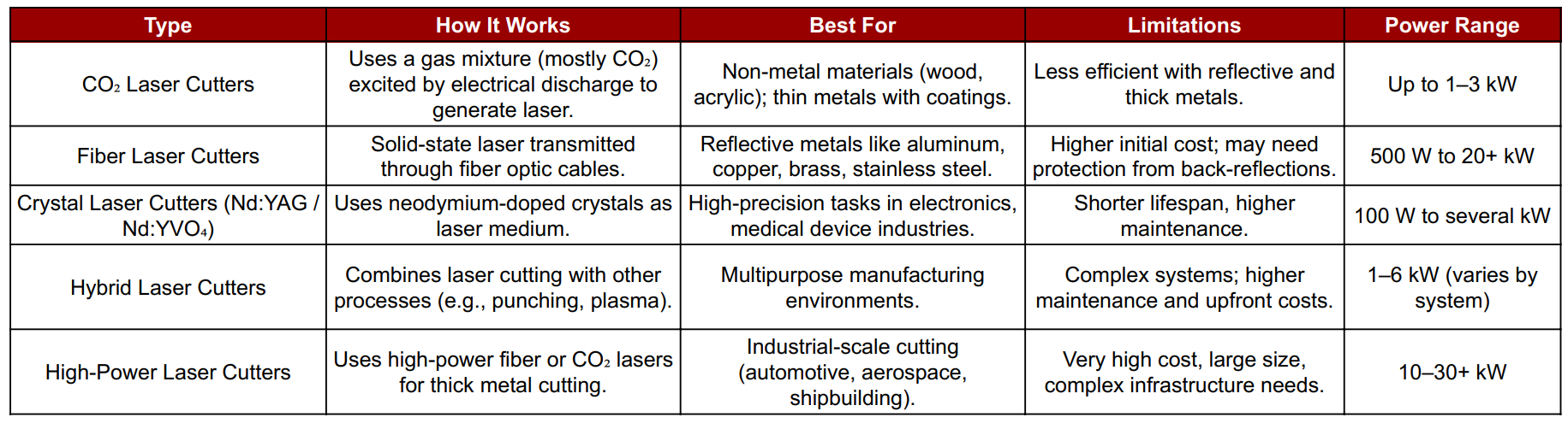
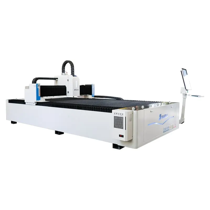
The WILA 3015 from WILA CNC Machine Tools Inc. is a high-performance metal laser cutting machine designed for precision and efficiency. It supports a wide range of metal materials and utilizes fiber laser technology to deliver clean and accurate cuts. With a spacious cutting bed (typically 3000 mm x 1500 mm), it’s ideal for both industrial-scale and custom fabrication work. The WILA 3015 integrates seamlessly with CAM software, allowing users to convert digital designs into precise, repeatable cuts, making it perfect for prototyping, production, and educational applications.
For the first step of my Wild Card Week project, I looked online for inspiration by downloading free 2D butterfly images. These images helped me visualize different design styles, shapes, and patterns. I used platforms like Freepik and Pixabay to find high-quality resources that matched my creative vision for the project.
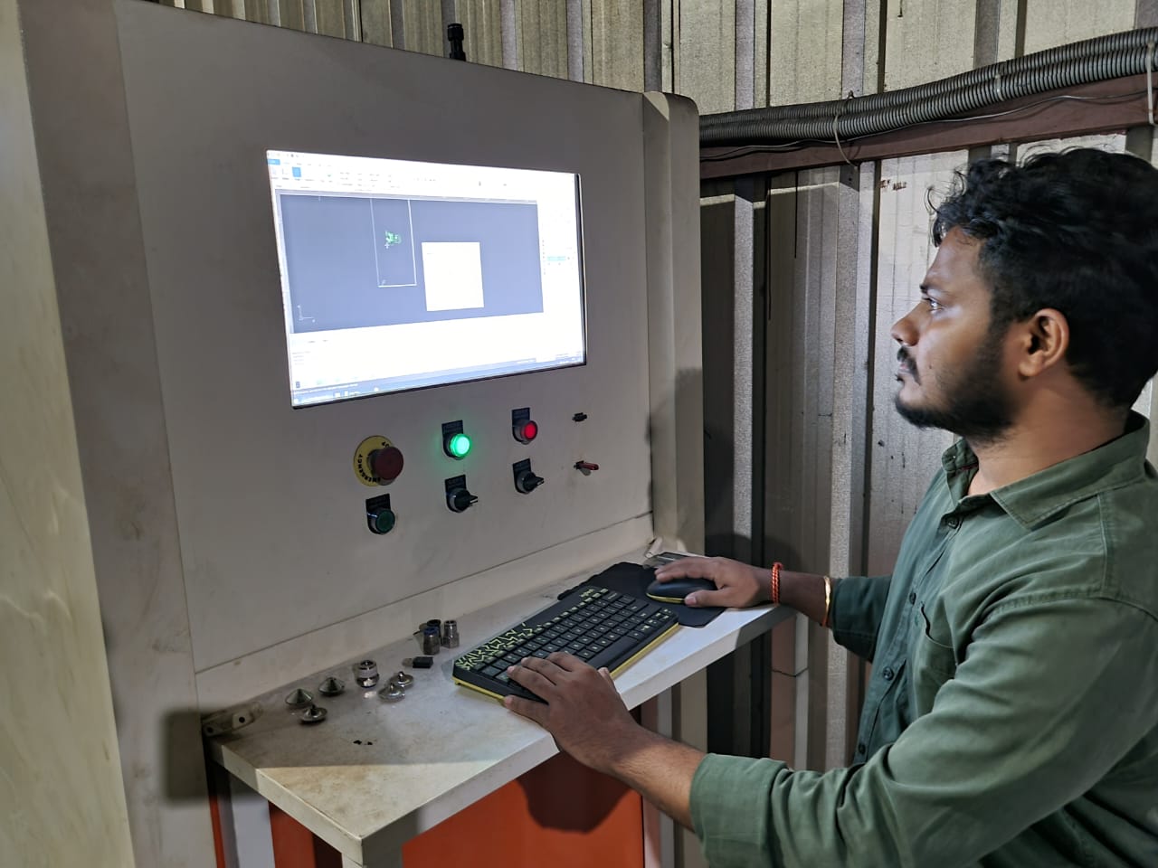
Next, I converted the downloaded 2D butterfly image into a DXF file format using vector design software. This format is compatible with laser cutting machines. After conversion, I transferred the DXF file to the laser cutter’s system, preparing it for accurate cutting by ensuring the paths and outlines were properly aligned.
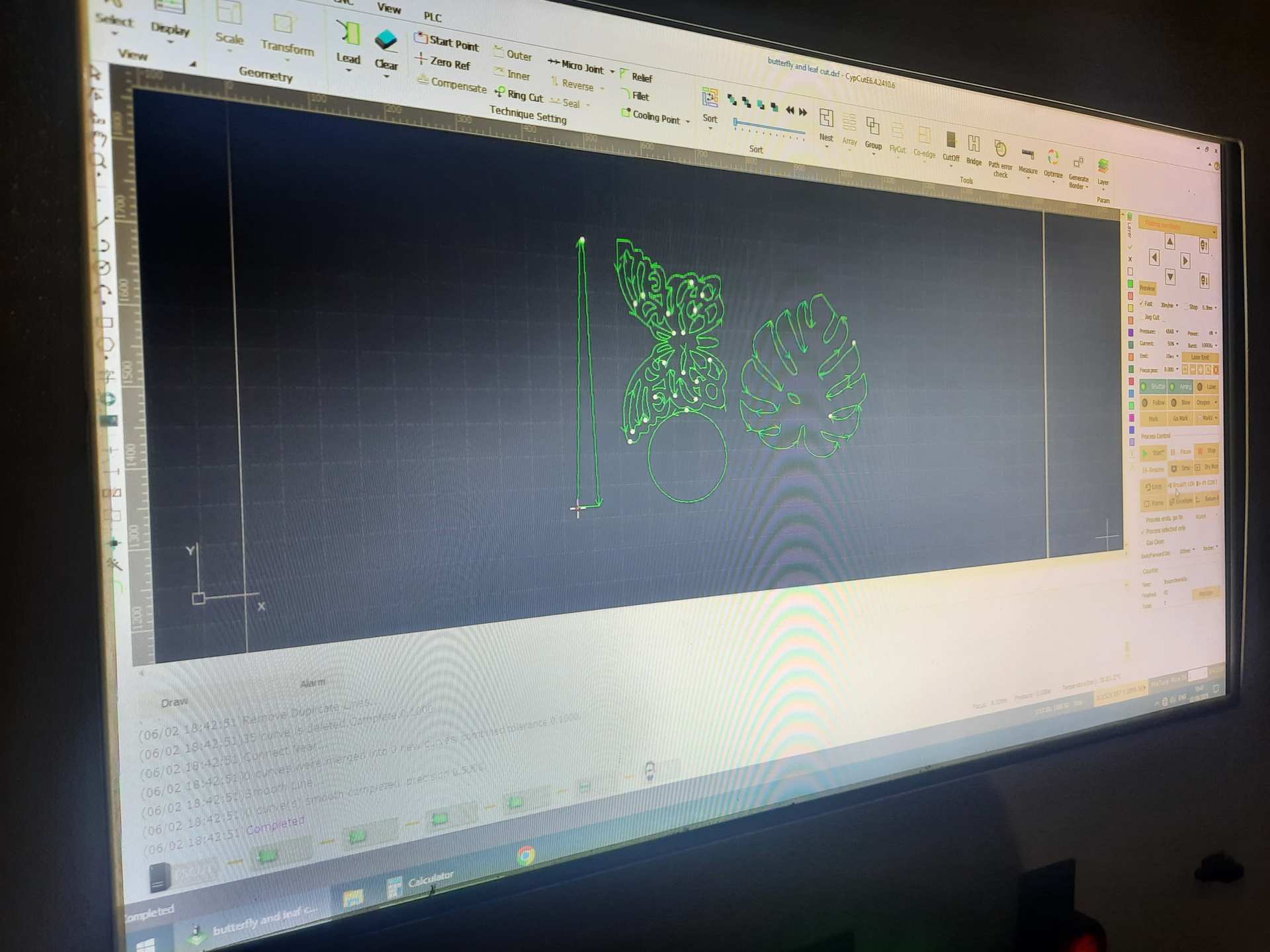
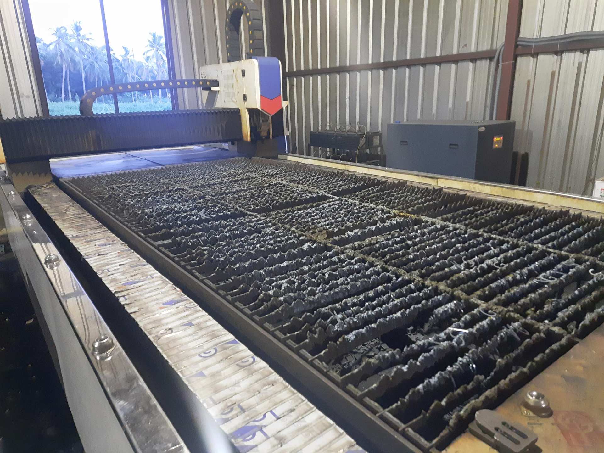
After transferring the DXF file to the laser cutter, I adjusted the cutting path to ensure smooth and precise outlines. I also configured key machine settings such as laser height, power, and speed according to the material type and thickness. These adjustments were crucial for achieving clean and accurate cuts.
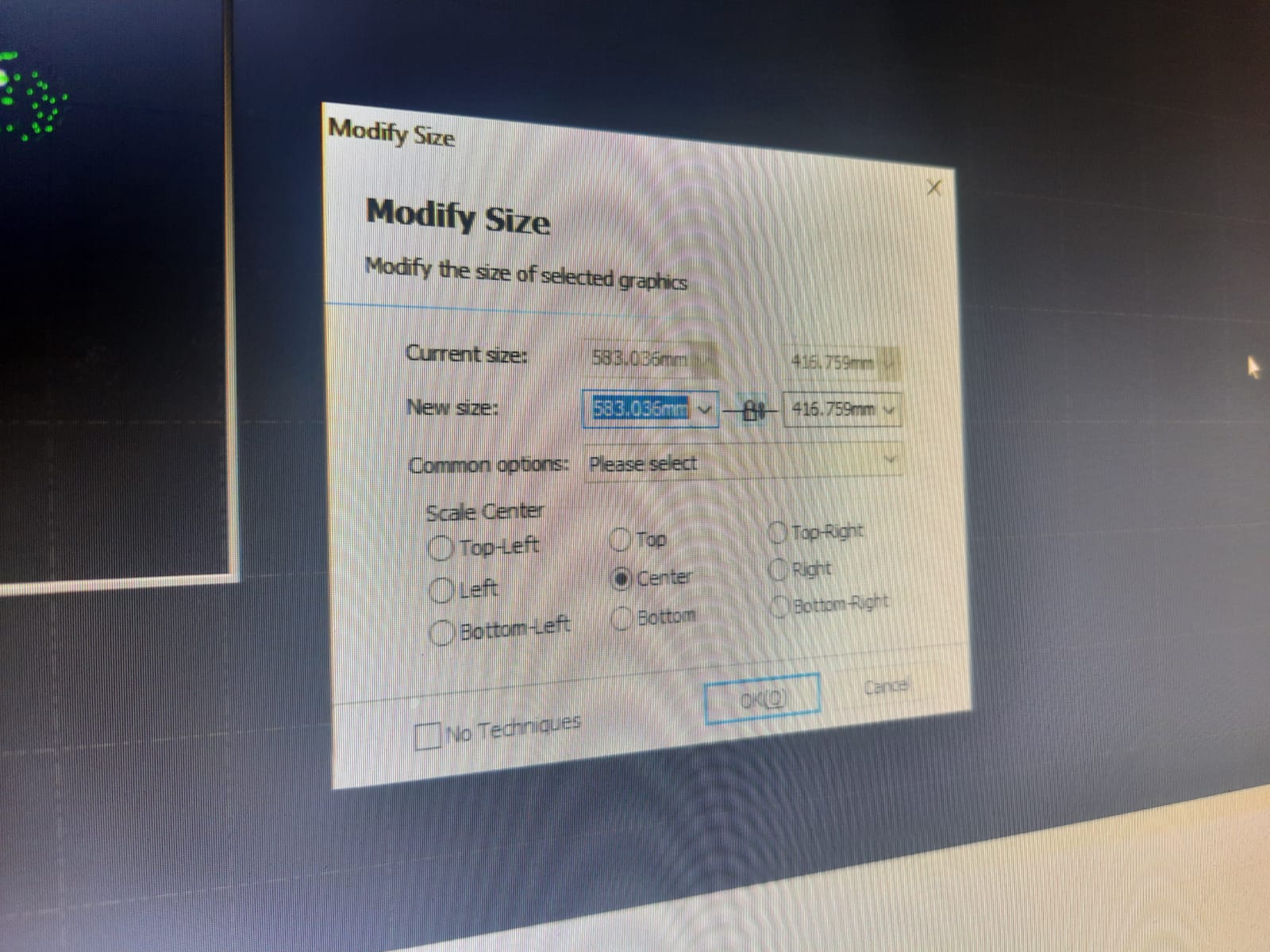
Once the cutting paths and settings were adjusted, I finalized the overall dimensions by setting the X and Y sizes to fit my design requirements. For this project, I chose a 0.8 mm thick CBR aluminum sheet as the material, which offers durability and a smooth surface ideal for precise laser cutting and detailed finishes.
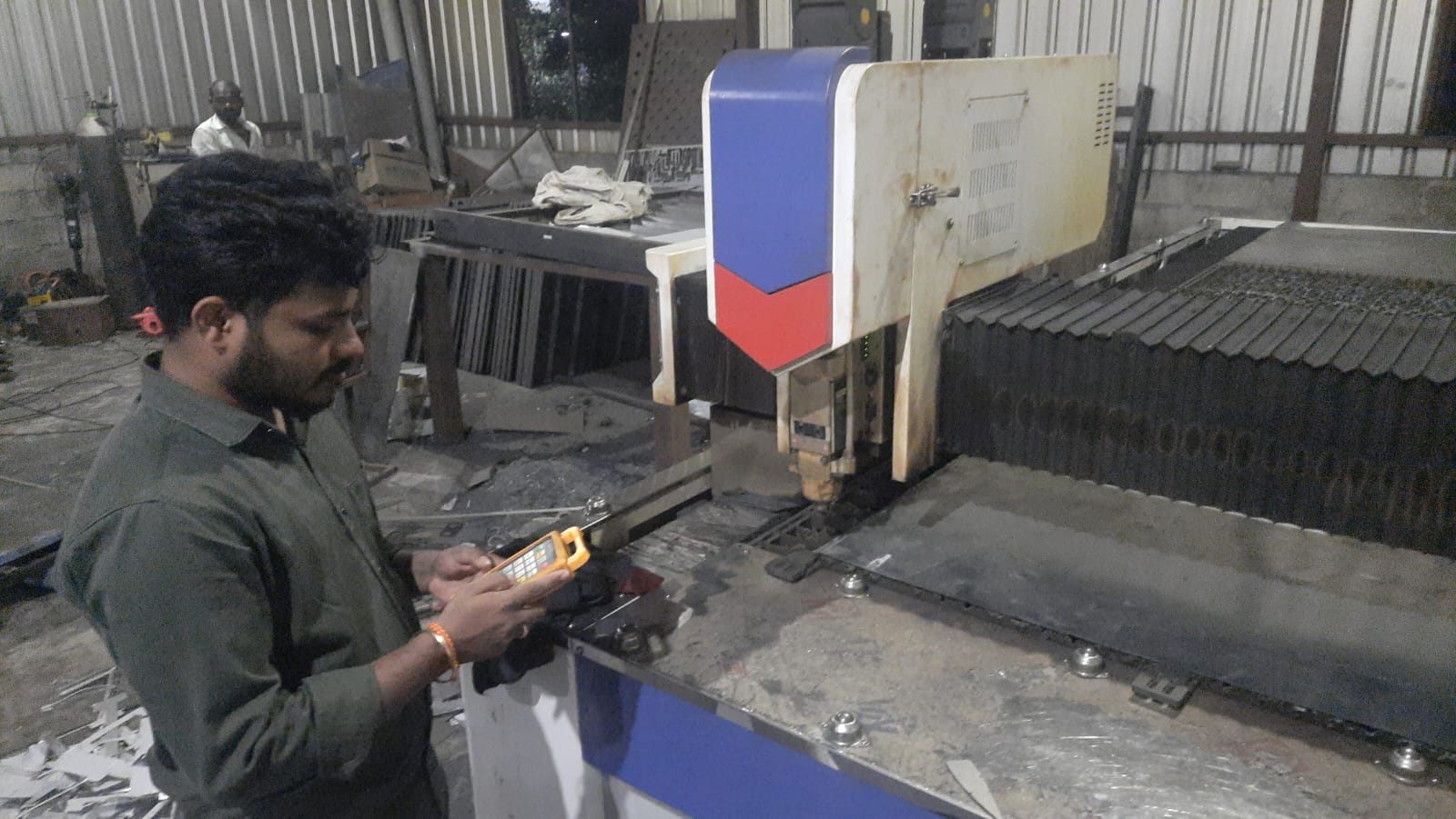
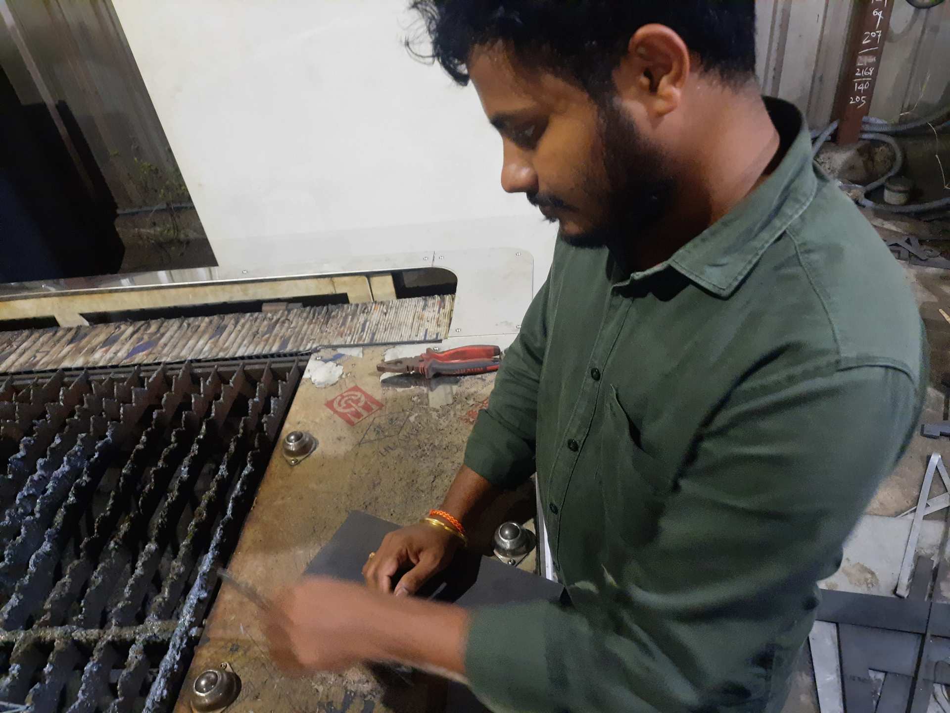
Next, I carefully fed the 0.8 mm CBR aluminum sheet into the laser cutting machine. I then set the origin point to define where the cutting would start. Before beginning the operation, I thoroughly checked the workspace to ensure the material was correctly positioned and that the cutting area aligned perfectly with the design.
After setting up everything, I executed the cutting process by starting the laser machine. I closely monitored the operation to ensure the laser followed the designated paths accurately, making clean cuts without damaging the material. This step required careful attention to achieve the desired quality and precision in the final butterfly design.
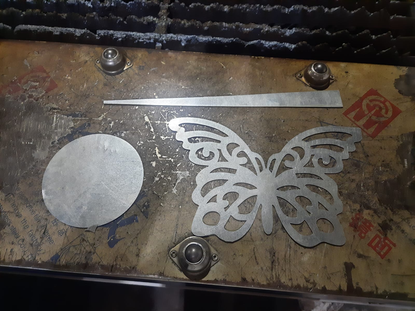
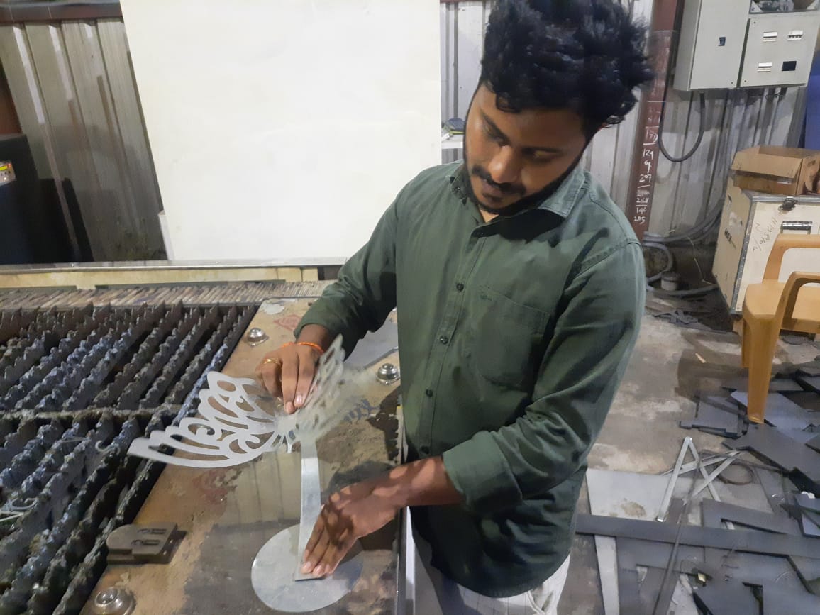
Here is the final output of the machined butterfly design. The laser cutting process precisely shaped the 0.8 mm CBR aluminum sheet, showcasing clean edges and intricate details. This finished piece reflects the careful planning, accurate settings, and effective execution throughout the entire fabrication process.
After the laser cutting was complete, I carefully removed the machined parts from the machine. I then thoroughly verified the dimensions to ensure they matched the design specifications accurately. This quality check was essential to confirm that the final piece met all the required measurements and maintained the intended precision.
Here, I simply held the finished piece to see how it looks in real life. This hands-on inspection helped me appreciate the design’s details, the smoothness of the cuts, and the overall craftsmanship. It’s an important moment to connect the digital work with the physical outcome before any further finishing or assembly.
Finally, I welded the individual parts together to complete the assembly. Since the material thickness is just 0.8 mm, the structure has a slight wobble, which unexpectedly gives the butterfly a lively and dynamic feel. After welding, I carefully inspected the final piece for alignment and finish. The result is a fully assembled and visually appealing 3D butterfly form.