Group assignment
Individual assignments

NEW TO 3D PRINTING?
THAT’S OKAY. LET’S GET YOU UP TO SPEED.
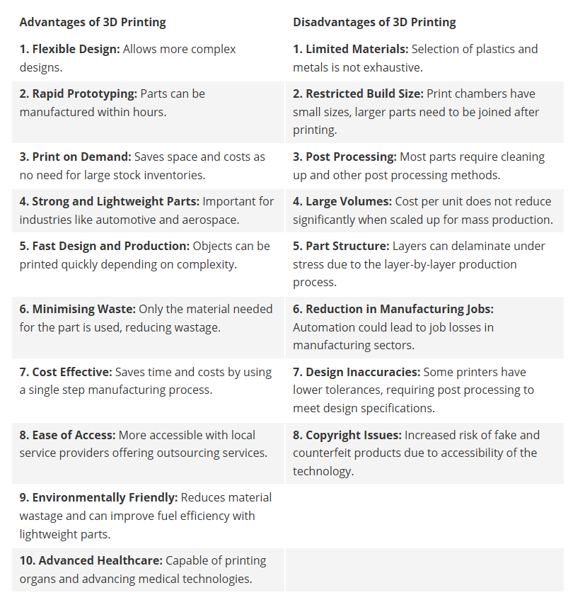
What is 3D Printing?
3D printing, also called additive manufacturing, is a process of creating three-dimensional solid objects from a digital file. Unlike traditional subtractive manufacturing (cutting/milling from a block), 3D printing adds material layer by layer, hence the term "additive."
Stages of 3D Printing
First, a digital 3D model of the object is created using computer-aided design (CAD) software such as Fusion 360, Tinkercad, or Blender. This design is then exported in a format like STL or OBJ. Next, slicing software processes this model and converts it into G-code. This code instructs the printer on how to move, where to extrude material, and how fast to print each layer. The 3D printer then reads this G-code and begins printing layer by layer until the object is complete.
Types of 3D Printing Technologies
Fused Deposition Modeling (FDM) is the most common technique. It works by heating and extruding thermoplastic filament through a nozzle onto the print bed. Common materials include PLA, ABS, and PETG.
Stereolithography (SLA) uses a UV laser or light projector to cure liquid resin layer by layer. It offers high resolution and is popular for dental models, jewelry, and detailed prototypes.
Selective Laser Sintering (SLS) fuses powdered materials such as nylon using a laser. It does not require support structures and is used in industrial and mechanical applications.
Other technologies include Digital Light Processing (DLP), Multi Jet Fusion (MJF), Binder Jetting, Electron Beam Melting (EBM), and Direct Energy Deposition (DED), which are more specialized and often used in high-end or industrial applications.
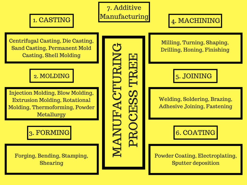
Manufacturing is defined as the conversion of raw materials into the finished goods on a large scale using man and machine whereas manufacturing processes are defined as the methods used for conversion of raw materials into finished products. Based on the product requirement there different types of manufacturing processes which are used to get the required output.
Some websites mention four types of manufacturing processes while some mention five types of manufacturing processes. Although, Wikipedia lists 7 main types of manufacturing processes which we are going to discuss below.
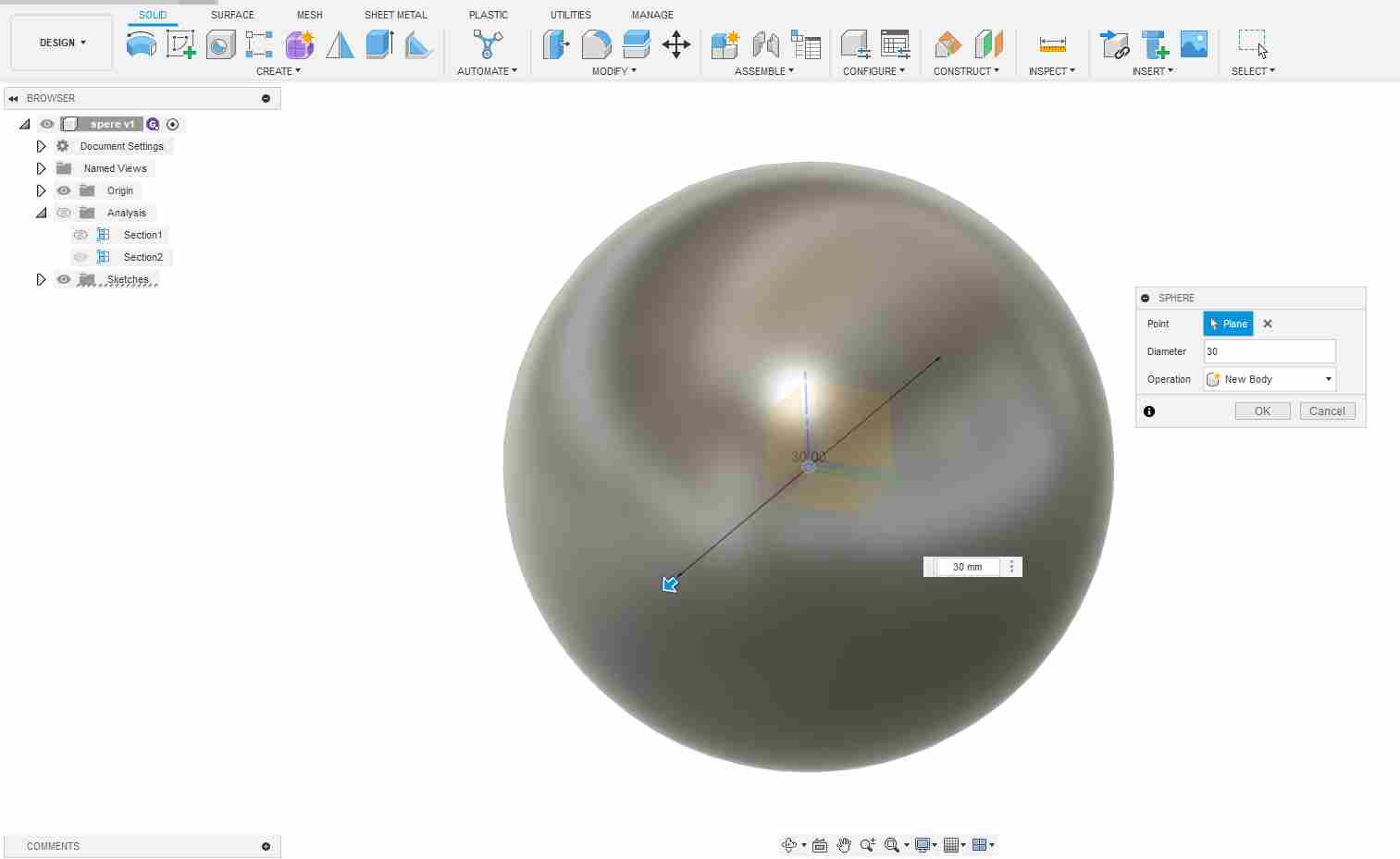
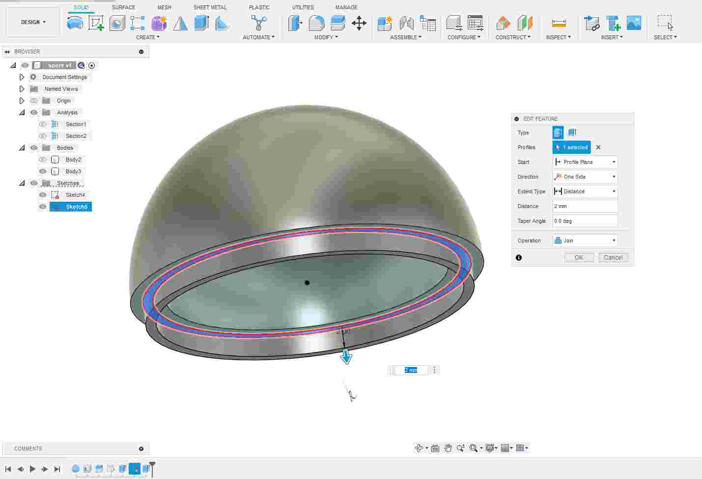
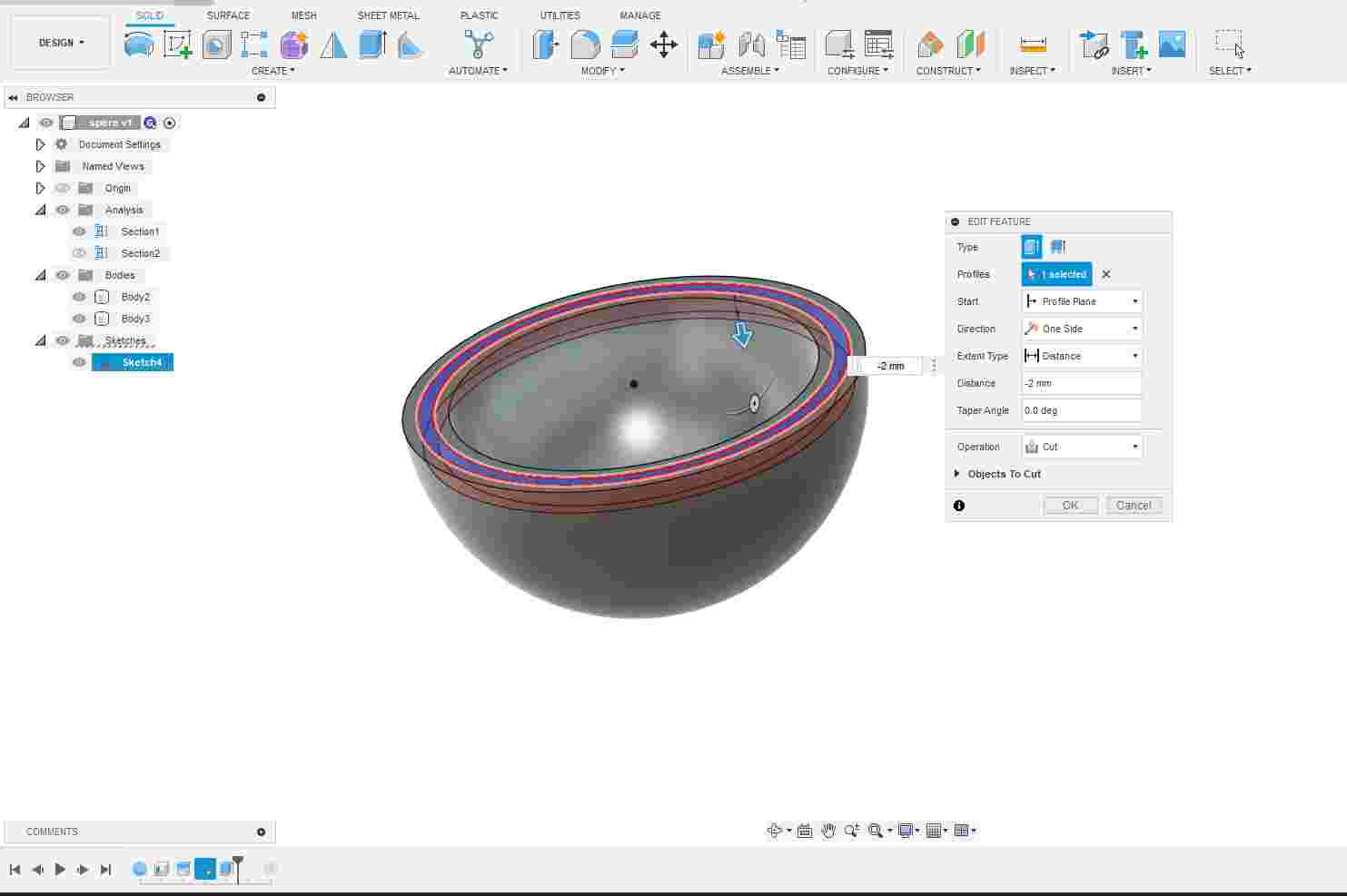
For this week's assignment, I explored various resources on the web and Thingiverse to find a suitable 3D-printable model. However, I couldn’t find an exact match, so I decided to design my own model for our final project. The main component I focused on is the outer shell. Additionally, for the Computer-Controlled Cutting assignment, I experimented with laser cutting a spherical shape.
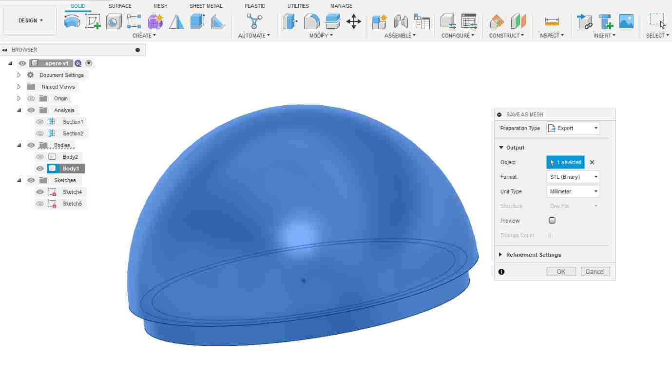
I exported the model as an STL file. This file format is commonly used for 3D printing, as it accurately represents the surface geometry of the model in a mesh of triangles. Exporting in STL allowed me to seamlessly import the design into slicing software like FlashPrint for 3D printing preparation.
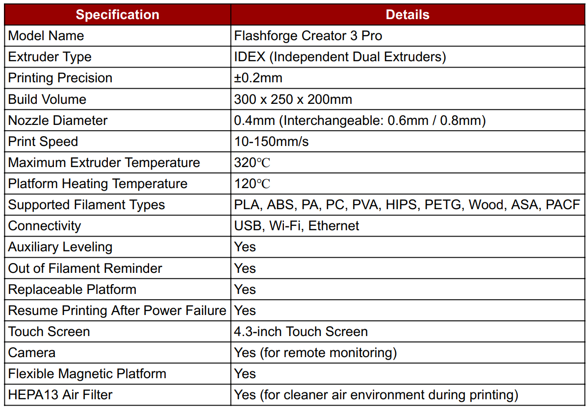
FlashPrint is the official slicing software developed by FlashForge for preparing 3D models for printing. It is user-friendly and supports both beginners and advanced users. With FlashPrint, you can import 3D models (STL, OBJ, 3MF), adjust settings like layer height, infill density, support structure, temperature, and slicing speed. It also provides features like model repair, auto-layout, and preview modes to simulate the final print. FlashPrint is optimized for FlashForge 3D printers and ensures seamless workflow from model design to final printing.
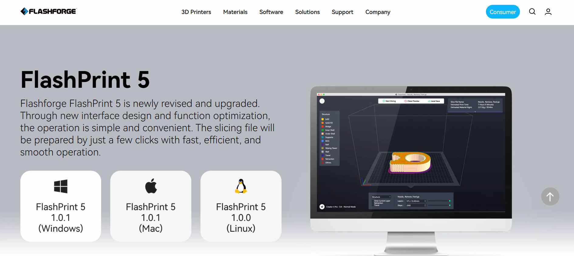
Flash Print 5 software File Link
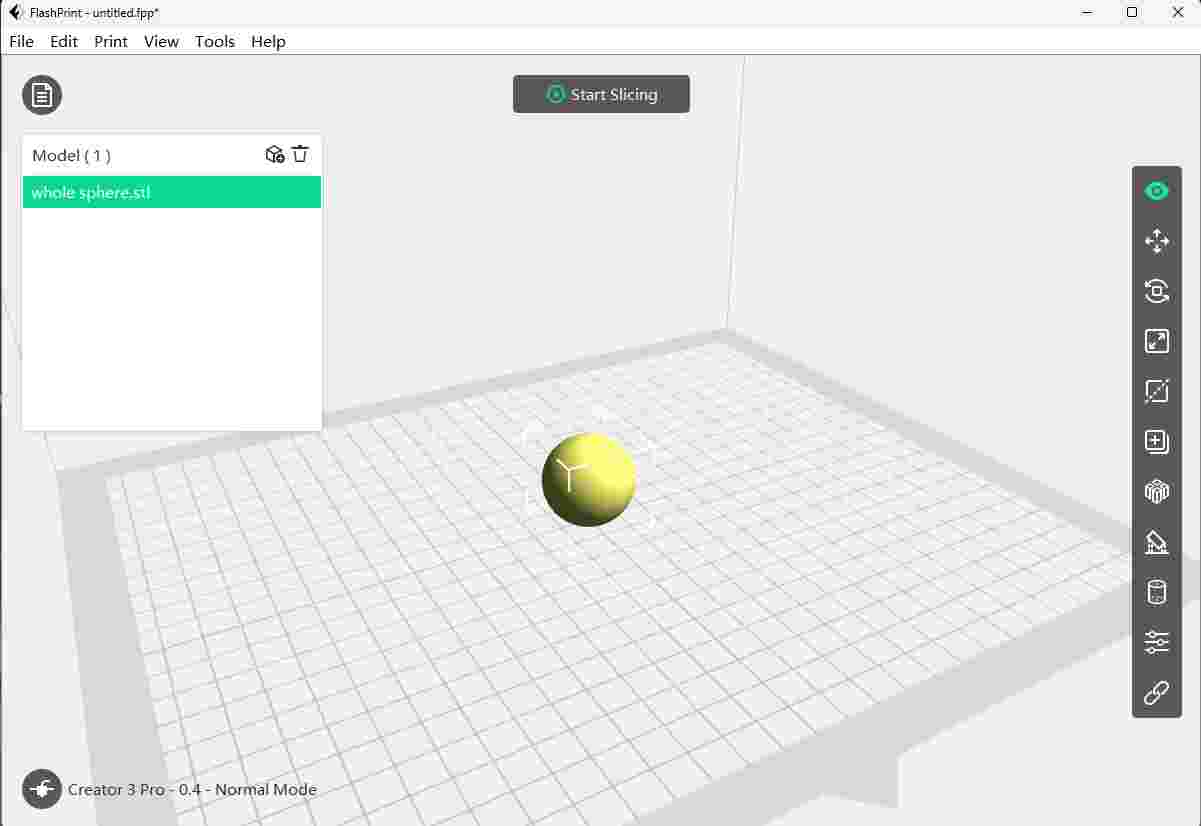
To begin 3D printing, I opened FlashPrint, the slicing software for the SIP Tracker 2025. I imported my 3D model by selecting the “Load” option and choosing the .STL file. The model appeared in the workspace, ready for orientation, scaling, and slicing based on printer settings.
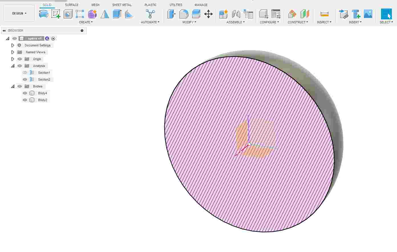
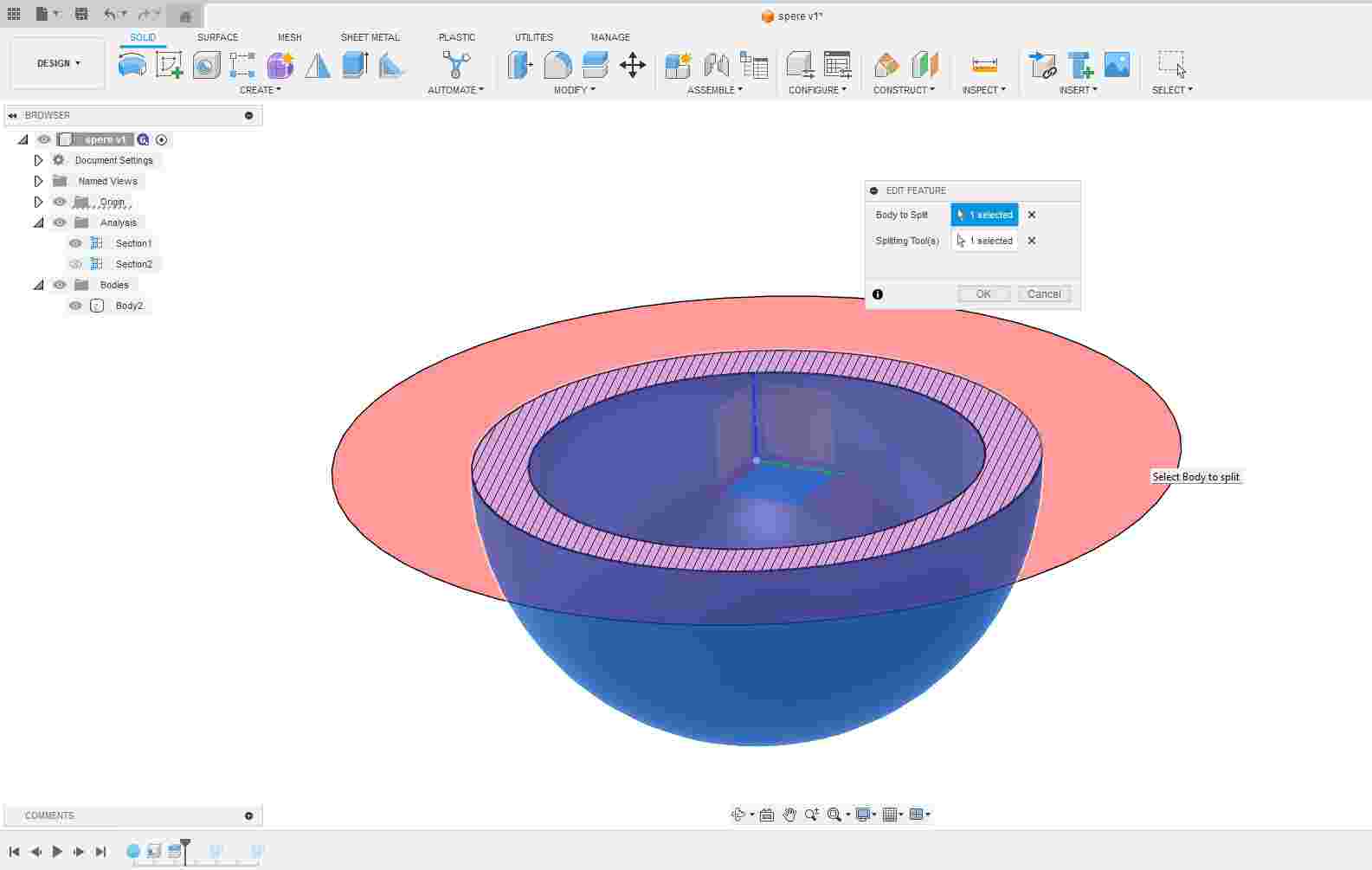
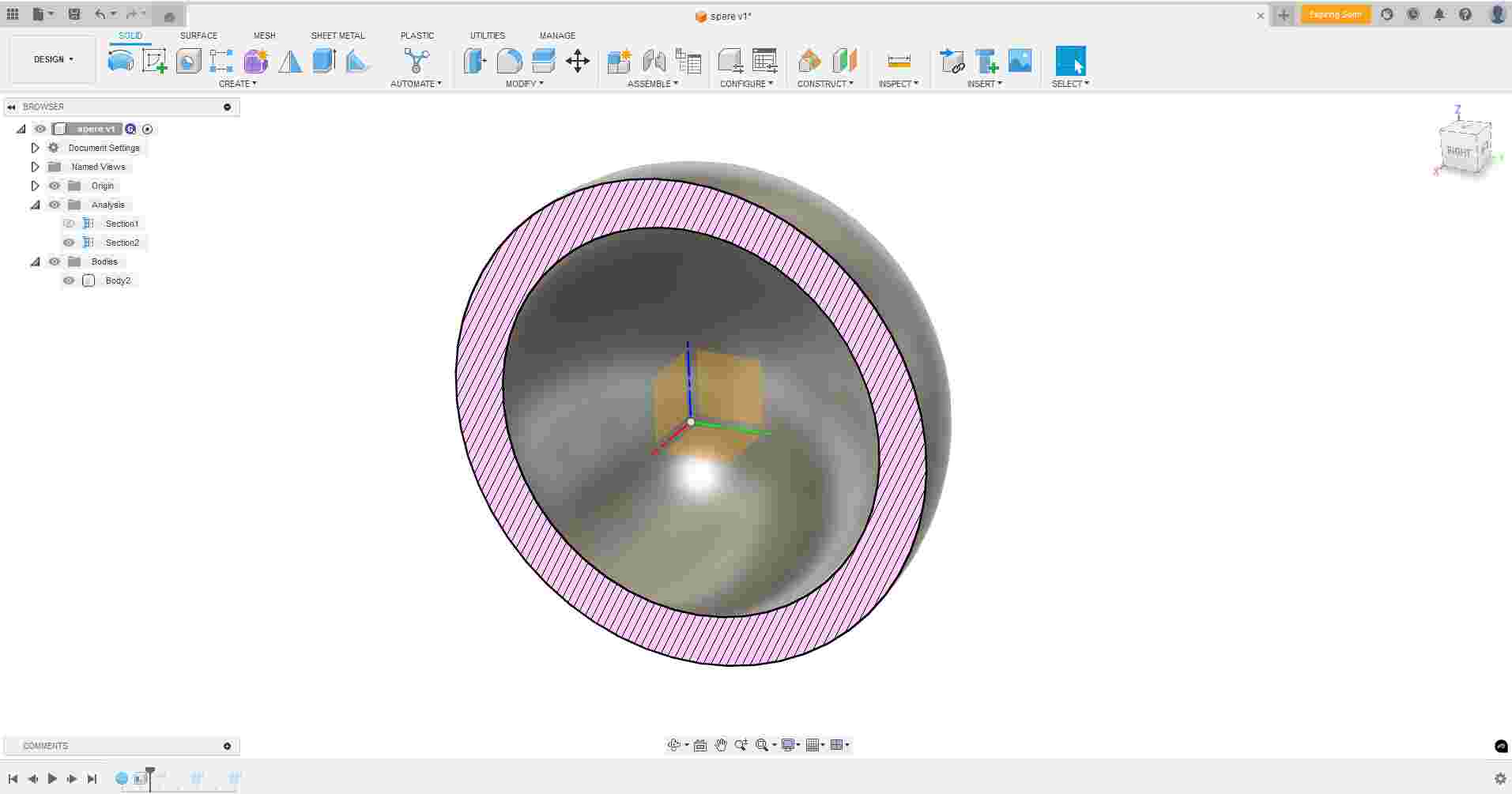
Creating a hollow sphere with uniform 2.5 mm wall thickness is not practical in subtractive manufacturing due to
For Your Information
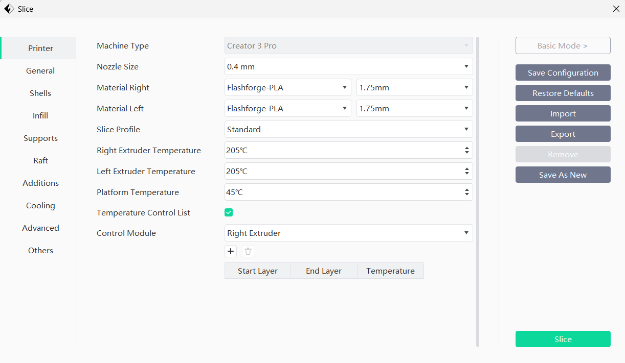
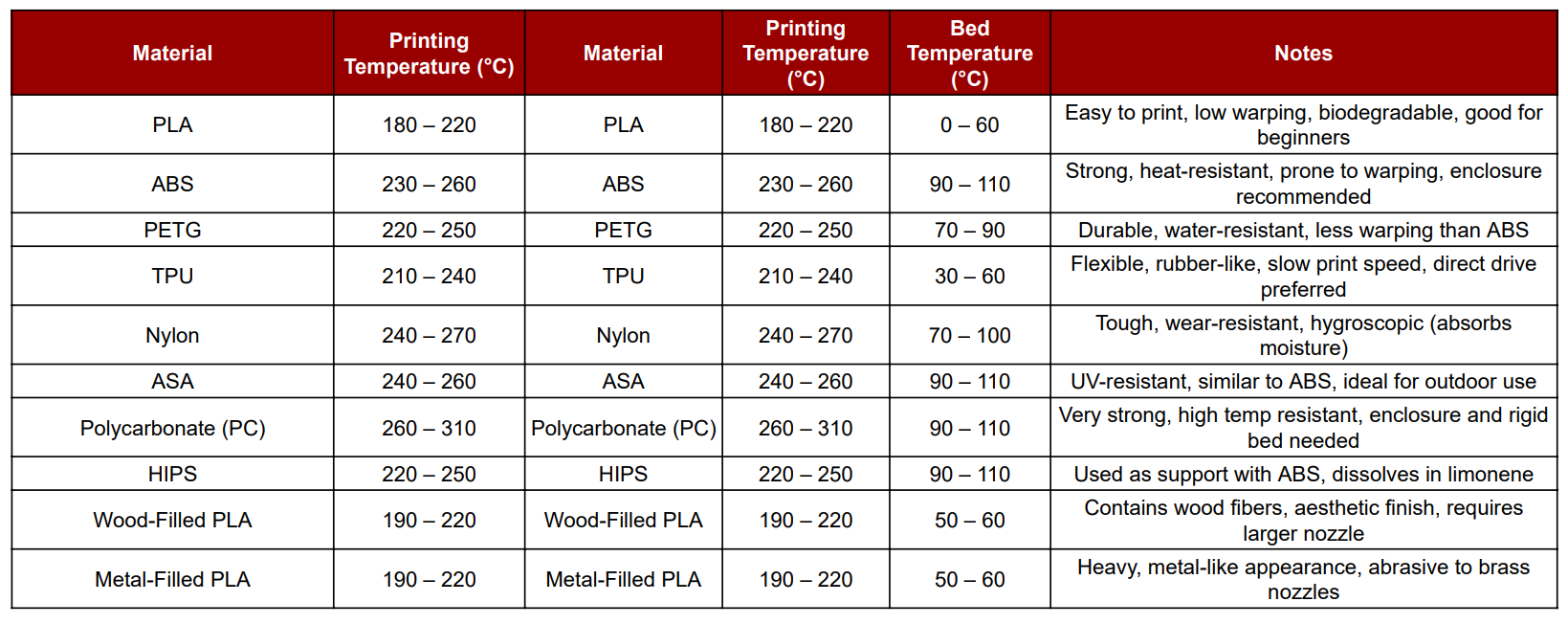
In FlashPrint, I selected PLA (Polylactic Acid) as the printing material, which is commonly used due to its ease of printing and eco-friendliness. Based on this choice, I adjusted the basic temperature settings: Nozzle Temperature: 200°C (typical for PLA)
Bed Temperature: 60°C (to ensure good first layer adhesion) These settings help in achieving optimal print quality and minimizing warping or detachment during the print process.
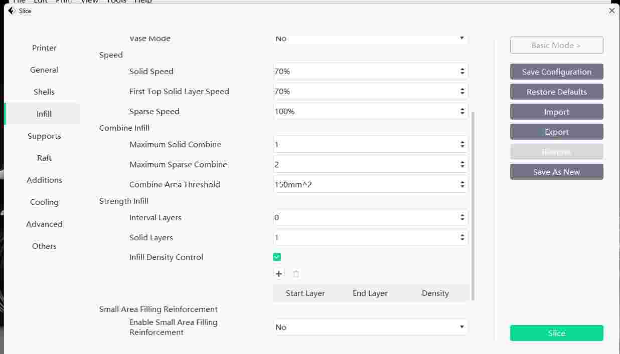
In FlashPrint, I customized several print parameters to optimize quality and strength. I adjusted the infill density for structural strength, print speed for precision, bed temperature to ensure adhesion, nozzle temperature for proper extrusion, and selected an appropriate infill pattern such as grid or honeycomb.
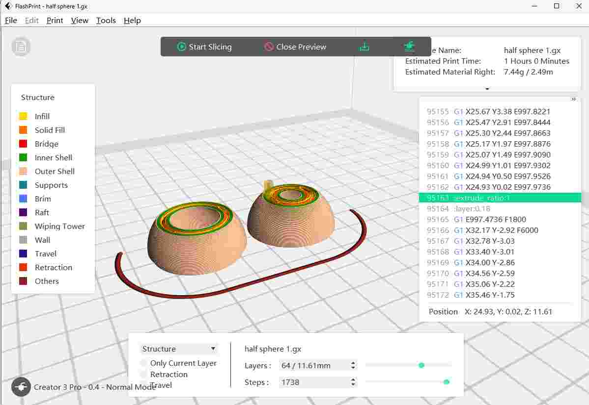
verify with preview options After configuring all the print settings, I used the Preview option in FlashPrint to simulate the print process. This allowed me to visually inspect the layer-by-layer path, estimated time, and material usage, ensuring that the model was properly sliced and ready for error-free 3D printing.
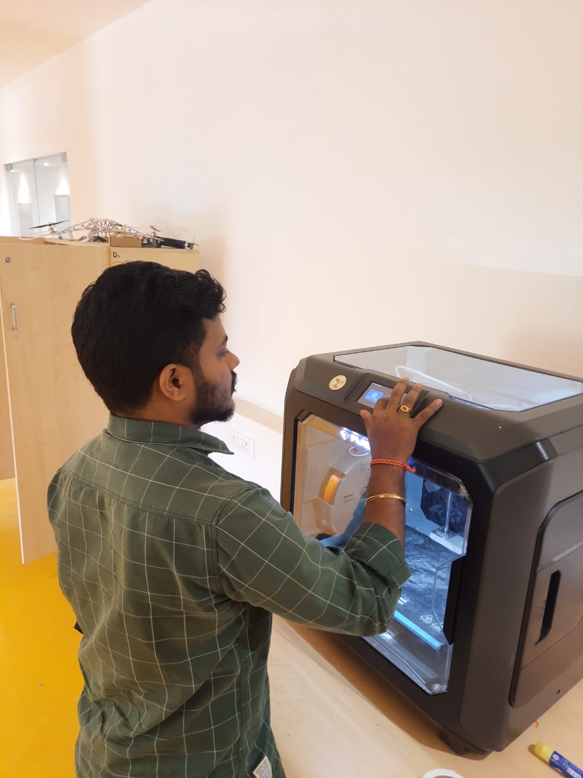
In the FlashForge machine, I loaded PLA material in orange color. I ensured the filament was properly fed into the extruder, checked that the nozzle was clean, and confirmed that the material flowed smoothly before starting the print. This setup prepared the printer for accurate and vibrant 3D printing.
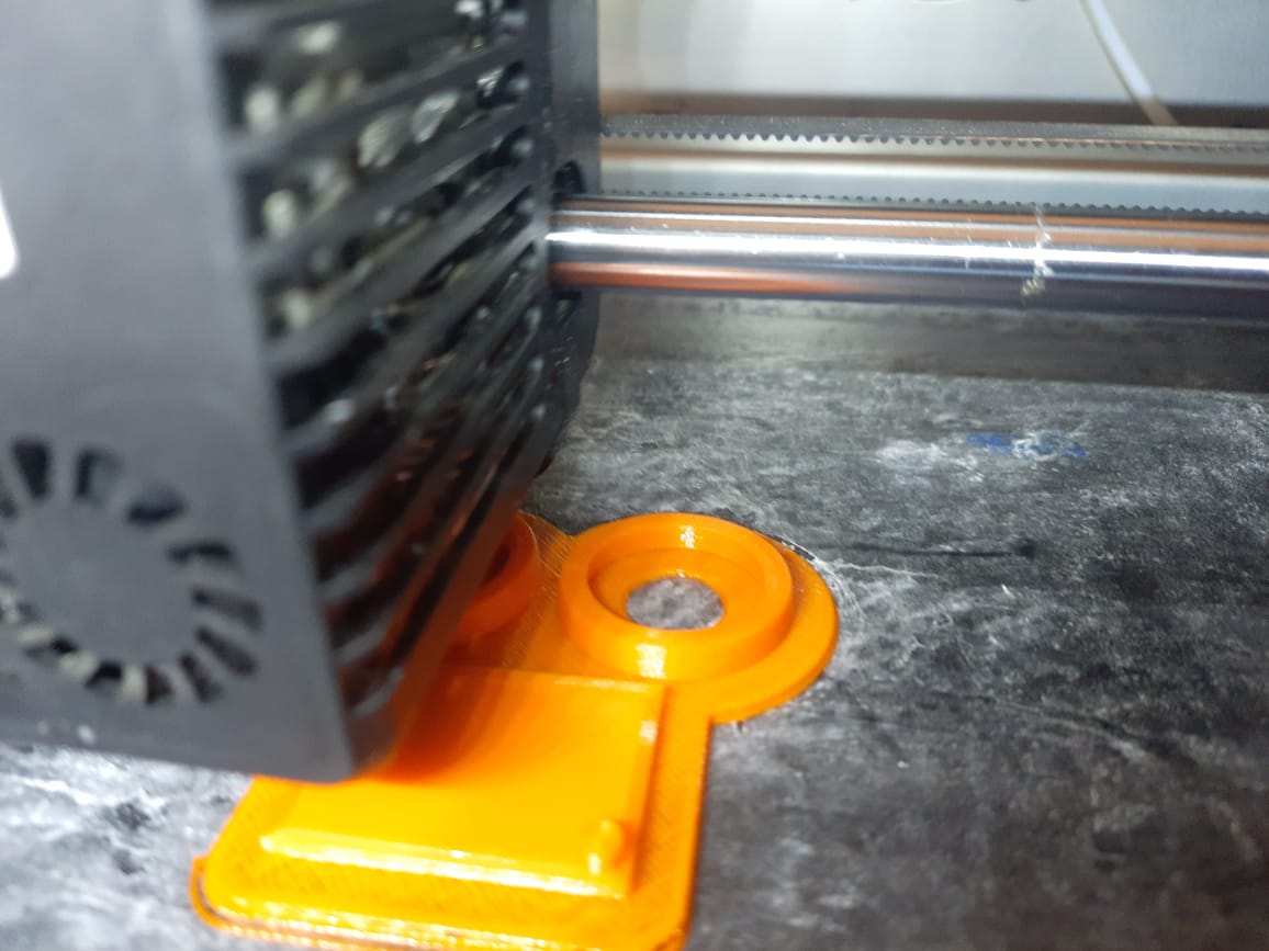
Once the slicing was complete, I transferred the G-code file to the FlashForge 3D printer via USB. The printer began building the model layer by layer. I closely monitored the initial layer adhesion, extrusion consistency, and temperature stability to ensure the print was progressing smoothly without issues like warping or shifting.
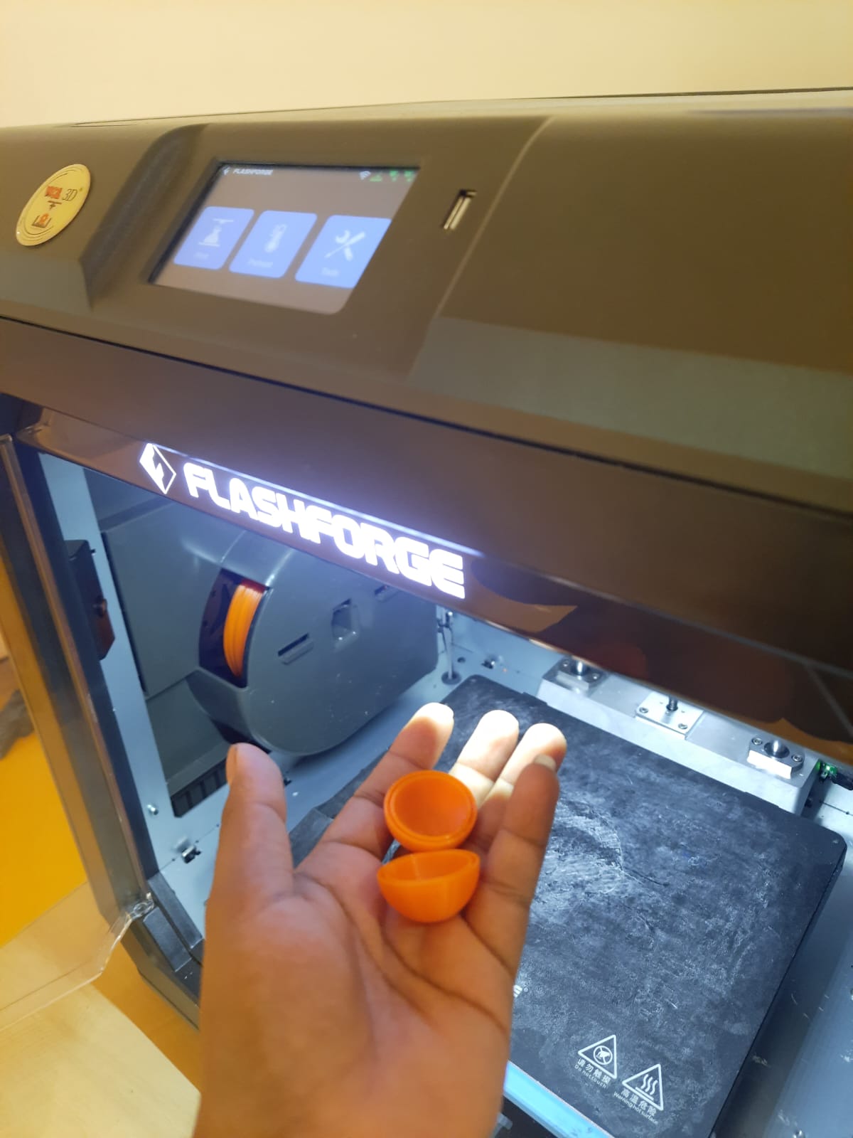
After the printing process was complete, I carefully removed the 3D printed part from the printer bed. The final model had clean edges and accurate dimensions as designed. I inspected the part for quality, verifying the layer finish, structural strength, and overall fit for its intended application.
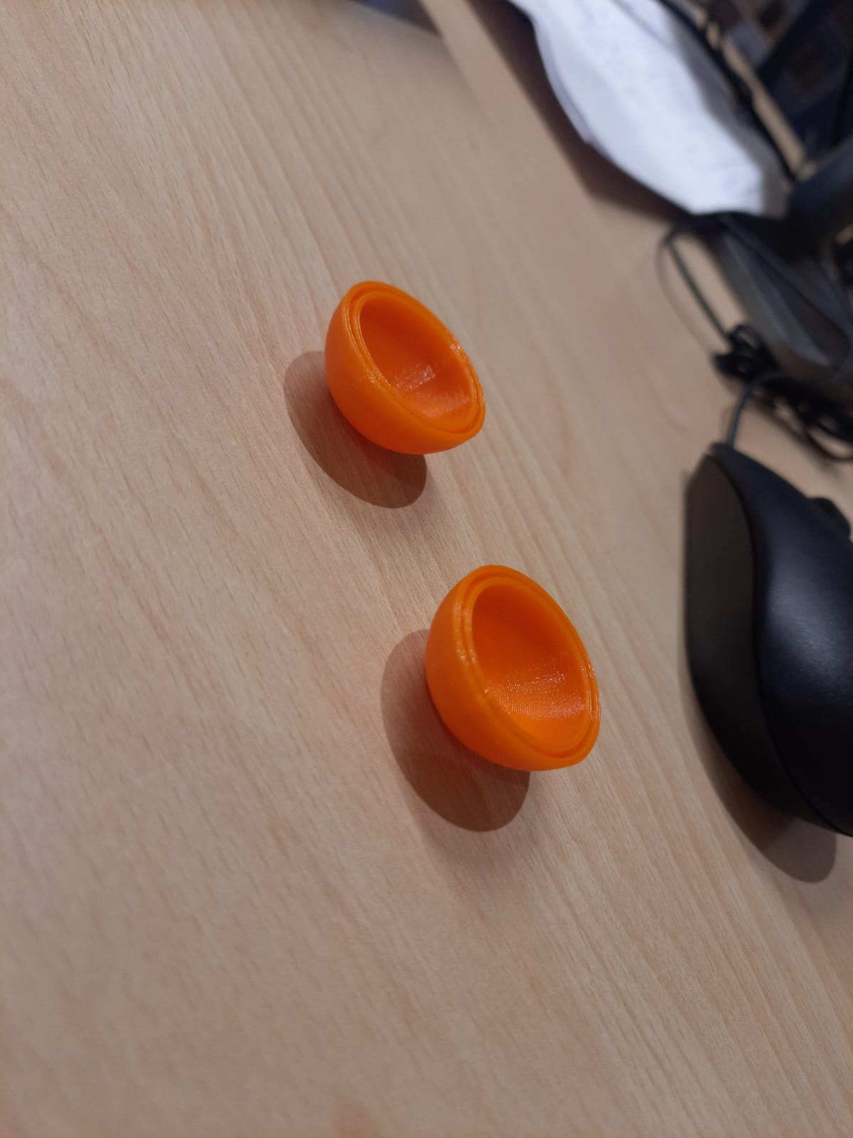
After 3D printing two components, I attempted to fit them together. However, I noticed that the parts did not align as expected due to tight tolerances. This revealed the need for additional clearance in the design. I decided to adjust the CAD model and reprint the parts for proper fitting.
3D scanning is the process of analyzing a real-world object or environment to collect three dimensional data of its shape and possibly its appearance (e.g. color). The collected data can then be used to construct digital 3D models. A 3D scanner can be based on many different technologies, each with its own limitations, advantages and costs. Many limitations in the kind of objects that can be digitized are still present. For example, optical technology may encounter difficulties with dark, shiny, reflective or transparent objects while industrial computed tomography scanning, structured-light 3D scanners, LiDAR and Time Of Flight 3D Scanners can be used to construct digital 3D models, without destructive testing. Collected 3D data is useful for a wide variety of applications. These devices are used extensively by the entertainment industry in the production of movies and video games, including virtual reality.
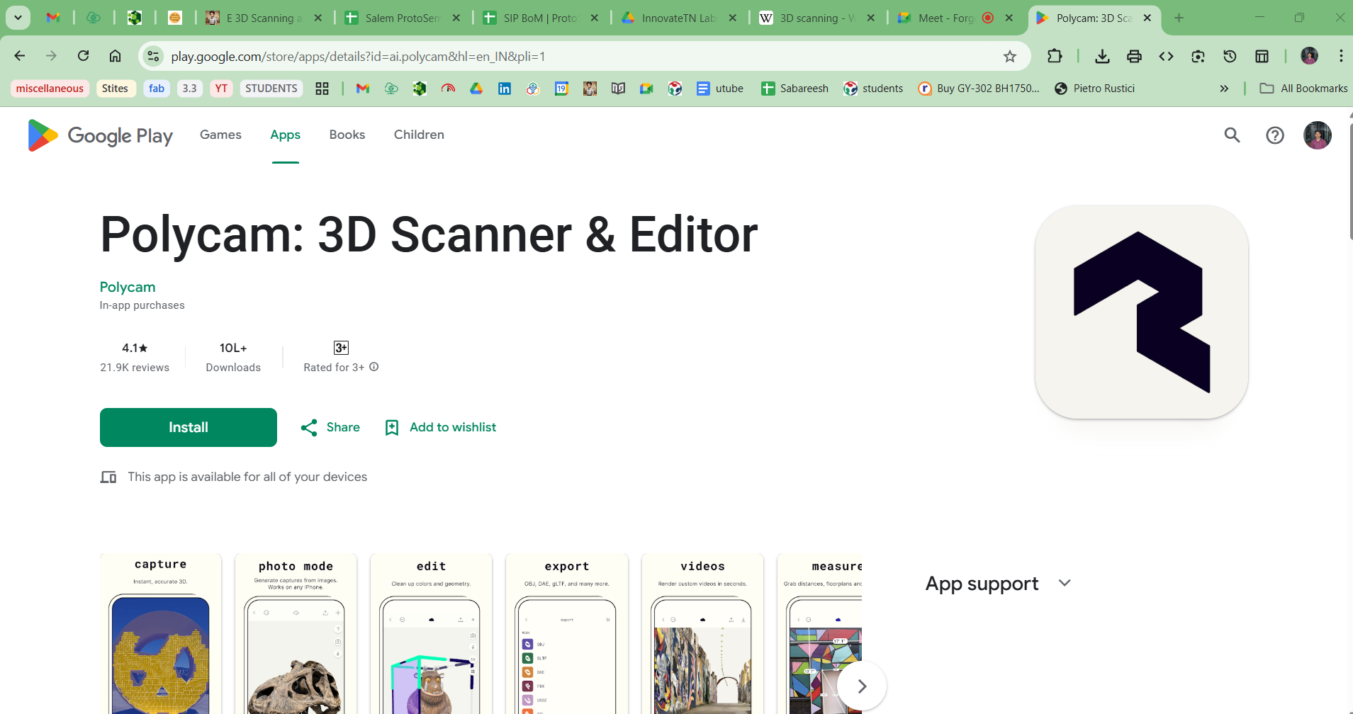
For my 3D scanning assignment, I chose to work with the Polycam application. It’s a user-friendly mobile scanning software that uses LiDAR or photogrammetry to generate accurate 3D models. I selected it for its ease of use, high-quality output, and compatibility with different export formats for further processing.
Polycam: 3D Scanner & Editor Play Store Link
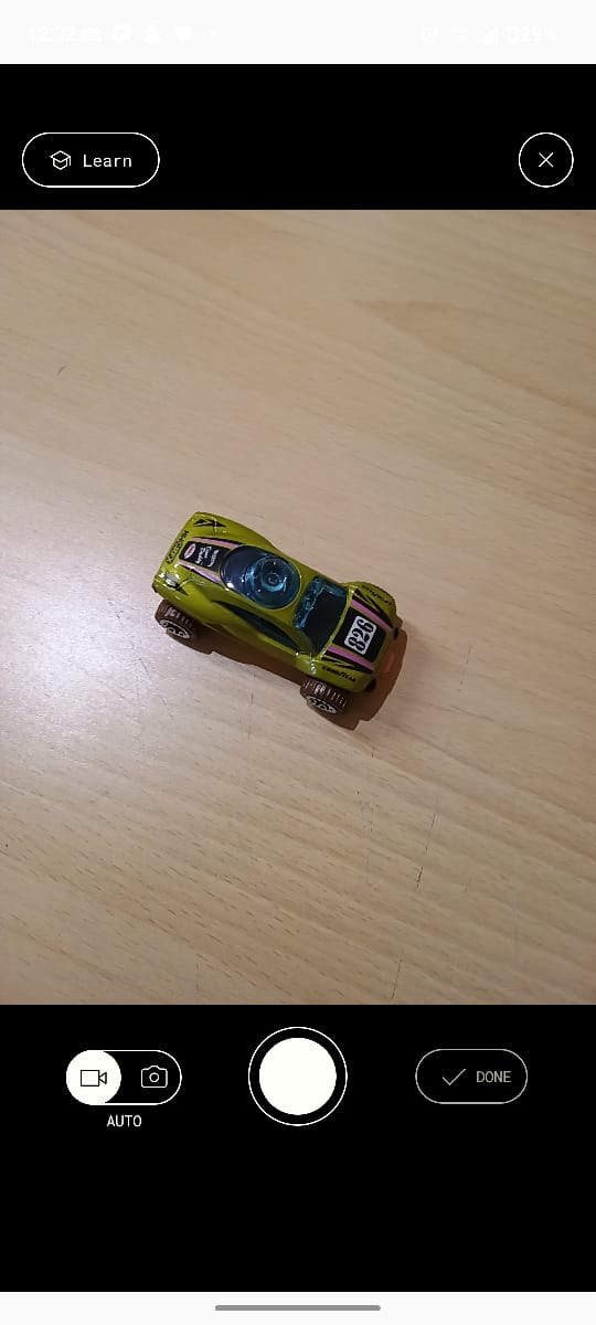
For the first step in the 3D scanning process, the object must be captured from multiple angles using the camera. I slowly moved around the object to ensure all sides, including top and bottom views, were covered. Capturing multiple perspectives helps the software accurately reconstruct a complete 3D model.
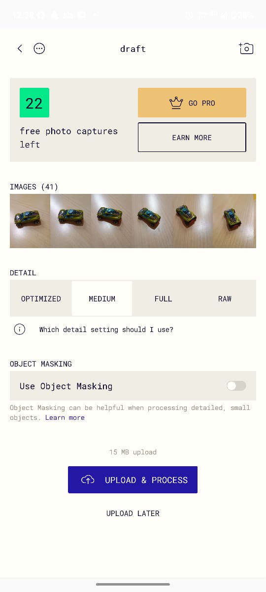

I captured a total of 41 images of the object from different angles to ensure complete coverage. After completing the photo capture, I selected the output quality as "Medium" to balance processing time and detail. Then, I proceeded to upload the images and initiated the 3D model processing in Polycam.
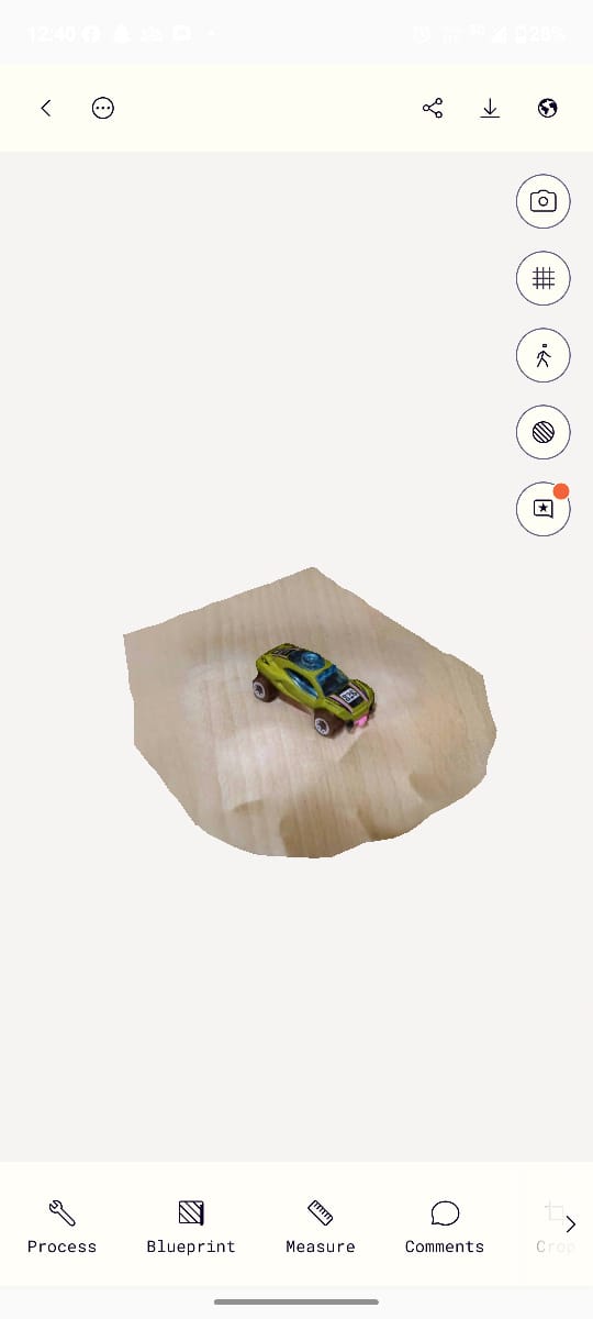
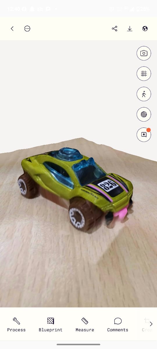
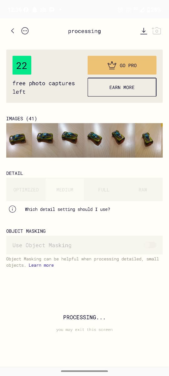
After uploading and processing the captured images in Polycam, I received the final output as a fully processed 3D model file. The software successfully reconstructed the object’s geometry and texture from the photos, resulting in a detailed 3D file that I can now use for viewing, editing, or exporting purposes.
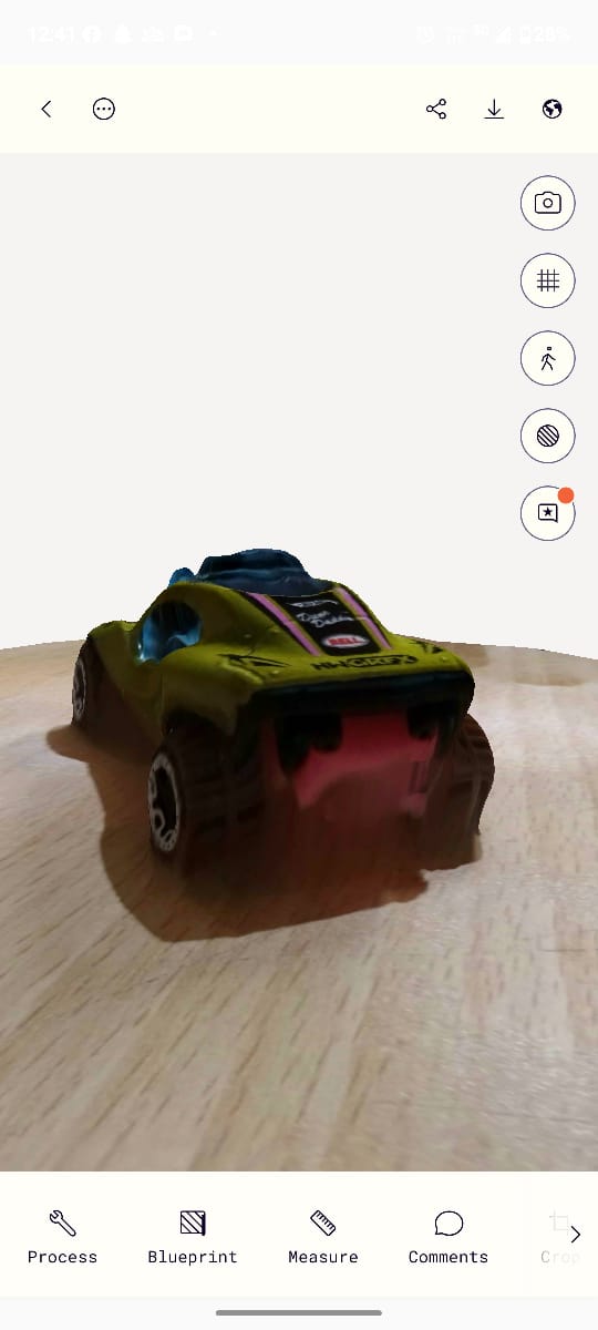
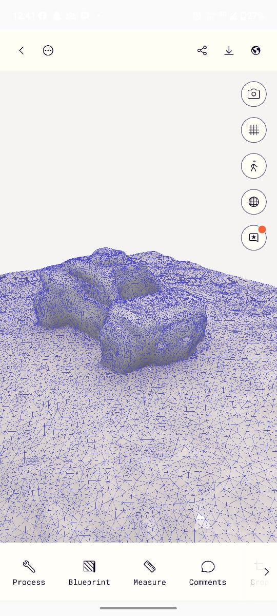
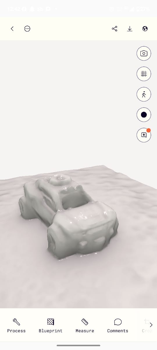
After receiving the processed 3D model in Polycam, I explored the multiple output formats available, such as mesh, textured, and point cloud models. Each format offered a different level of detail and use-case suitability, allowing me to analyze the object from various perspectives and select the best version for my needs.
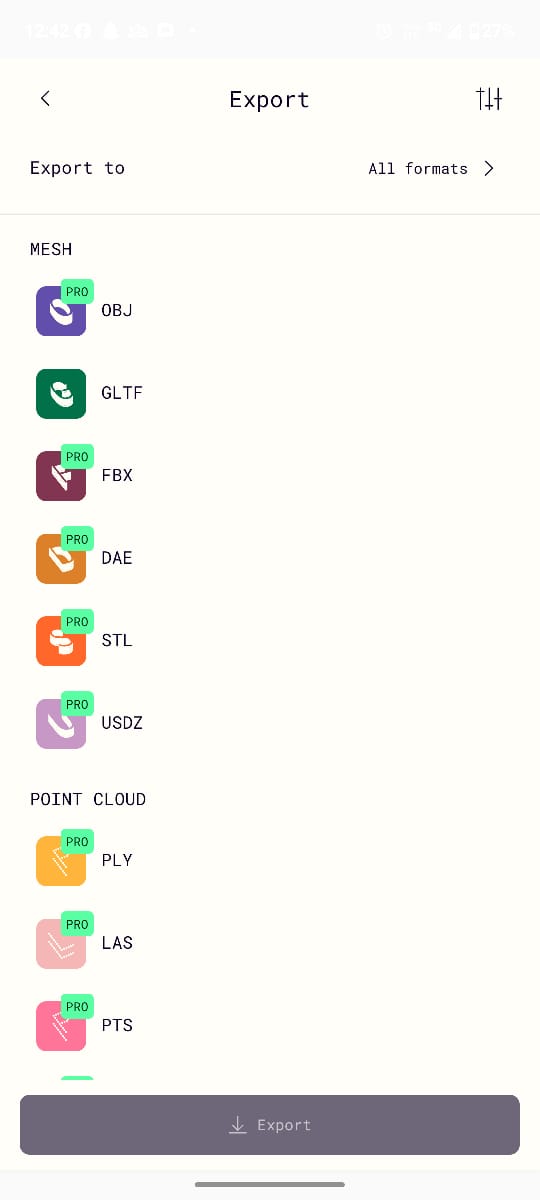
Although Polycam is a paid software, it allows limited free exports. I was still able to export the processed 3D model in .glb (GL Transmission Format), which is widely compatible with various 3D tools. I’ve attached the exported file, which includes detailed geometry and texture information from the scanned object.