Week 2
Computer-Aided Design
Inkscape is a free and open-source vector graphics editor used for creating and editing illustrations, logos, diagrams, and complex drawings. It supports the SVG (Scalable Vector Graphics) format, making it ideal for precise and scalable designs. Inkscape is widely used in digital fabrication, graphic design, and educational projects.
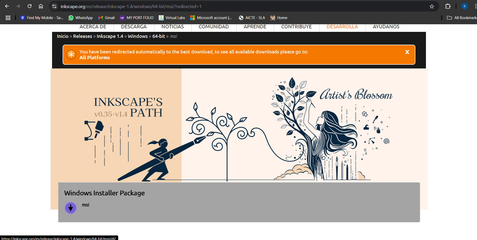
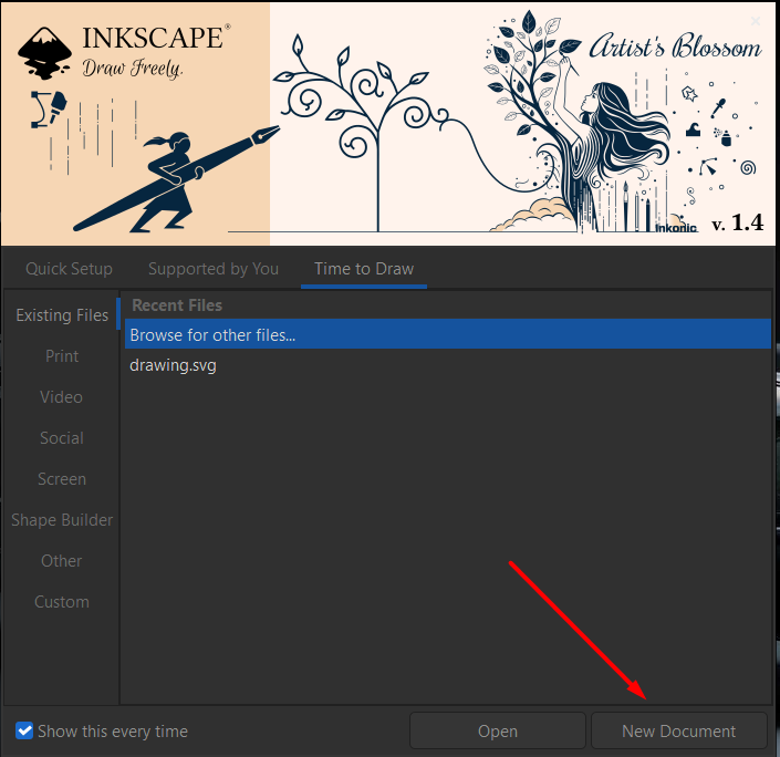
After downloading and installing Inkscape, I launched the software and opened a new document to begin designing. The interface provided a blank canvas with various drawing tools and settings, allowing me to start creating vector-based graphics right away for my project needs.
Once the new document was open, I explored the Inkscape interface, including the toolbars, menus, and working area. I familiarized myself with the drawing tools, object manipulation options, and alignment features. Understanding the workspace layout helped me navigate and use Inkscape more efficiently for vector design.
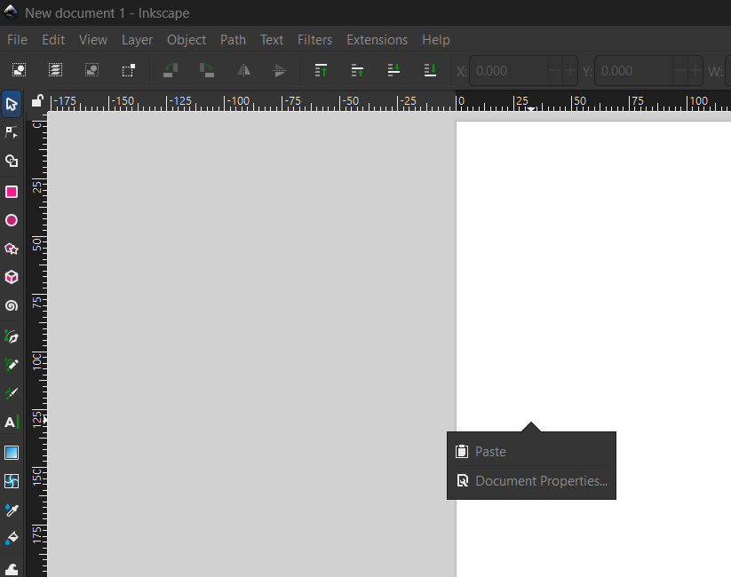
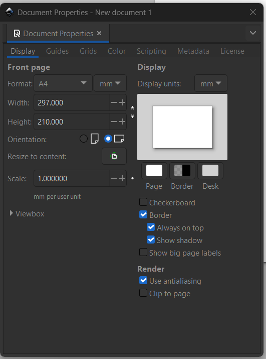
To better suit my design layout, I accessed the Document Properties in Inkscape and changed the page size to A4. I then switched the orientation from portrait to landscape. This provided a wider canvas, making it more convenient to arrange and work on my vector design elements.
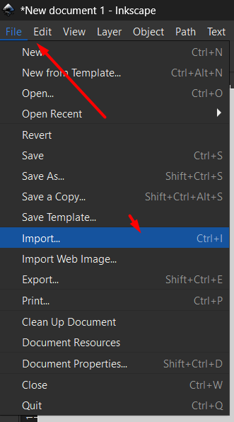
I selected File > Import and chose a JPEG image from my system. Inkscape prompted options for how to handle the image; I kept the default settings and clicked OK. The image was successfully imported into the canvas, ready for editing, tracing, or further design work.
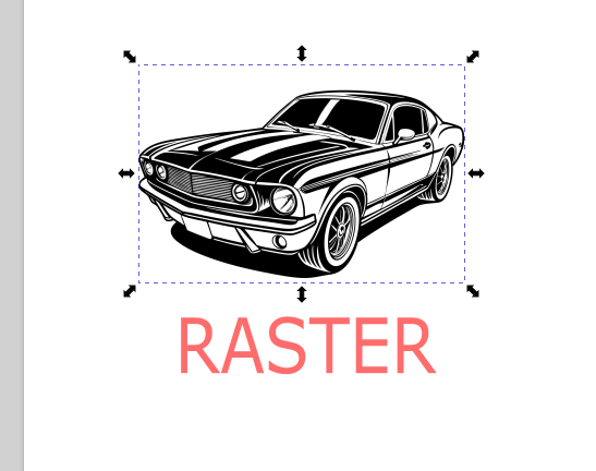
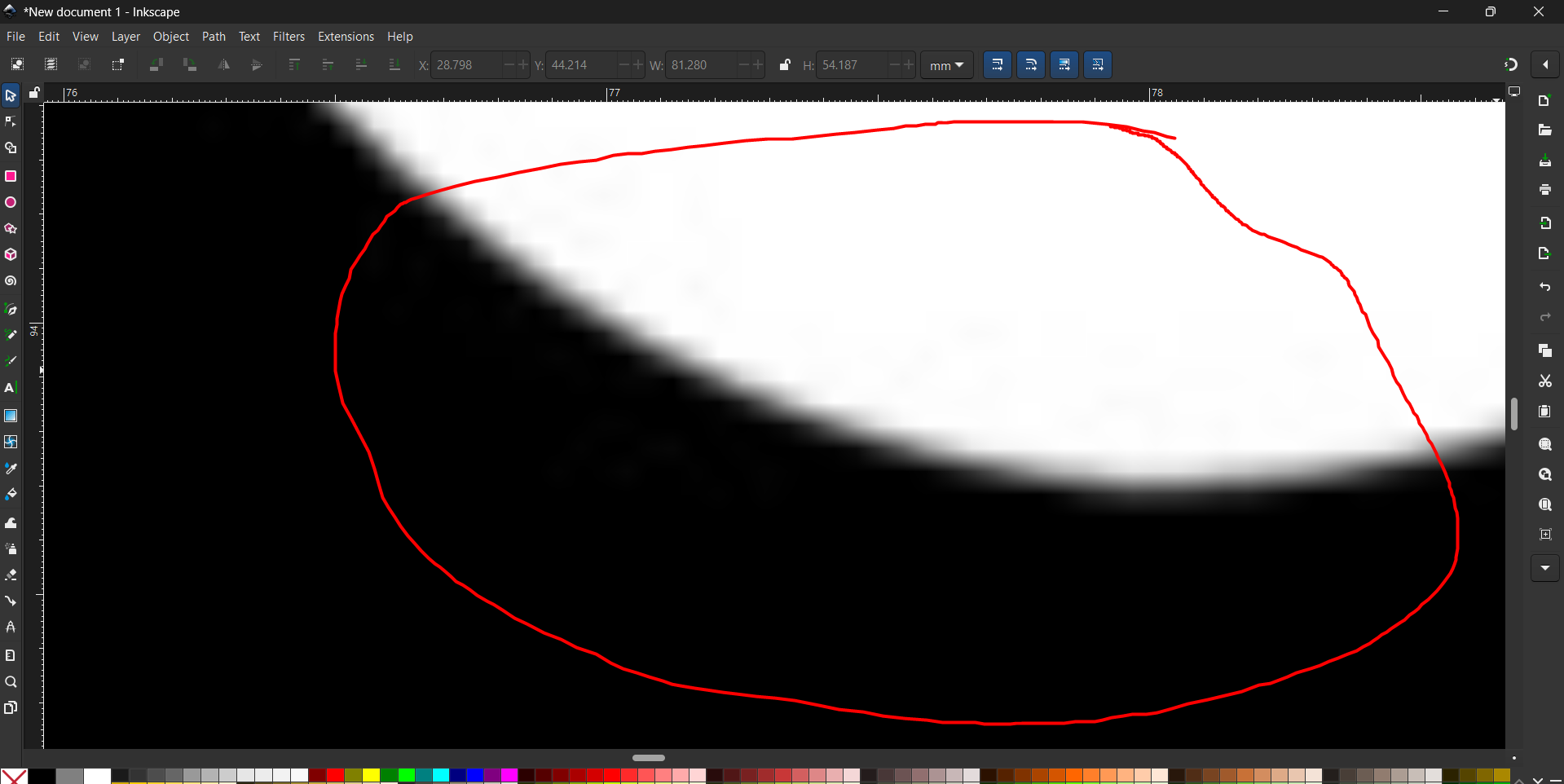
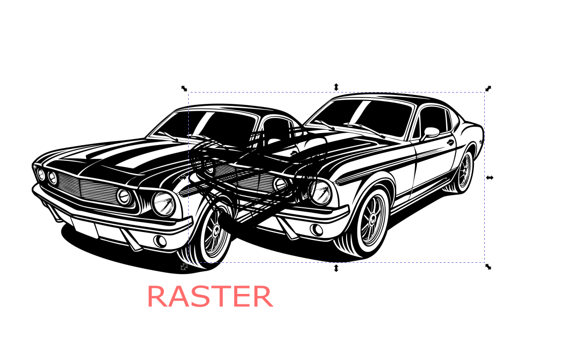
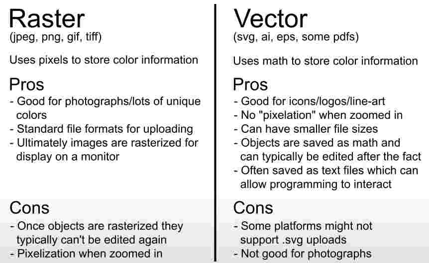
Since I imported a raster (JPEG) image, it appeared pixelated when scaled. Raster images are made of pixels and lose clarity when enlarged. This highlighted the difference between raster and vector graphics, where vector images remain sharp at any size, making them more suitable for precise design work.
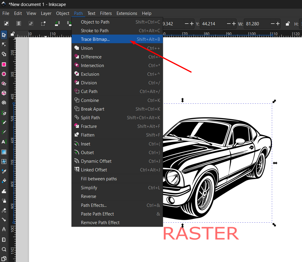
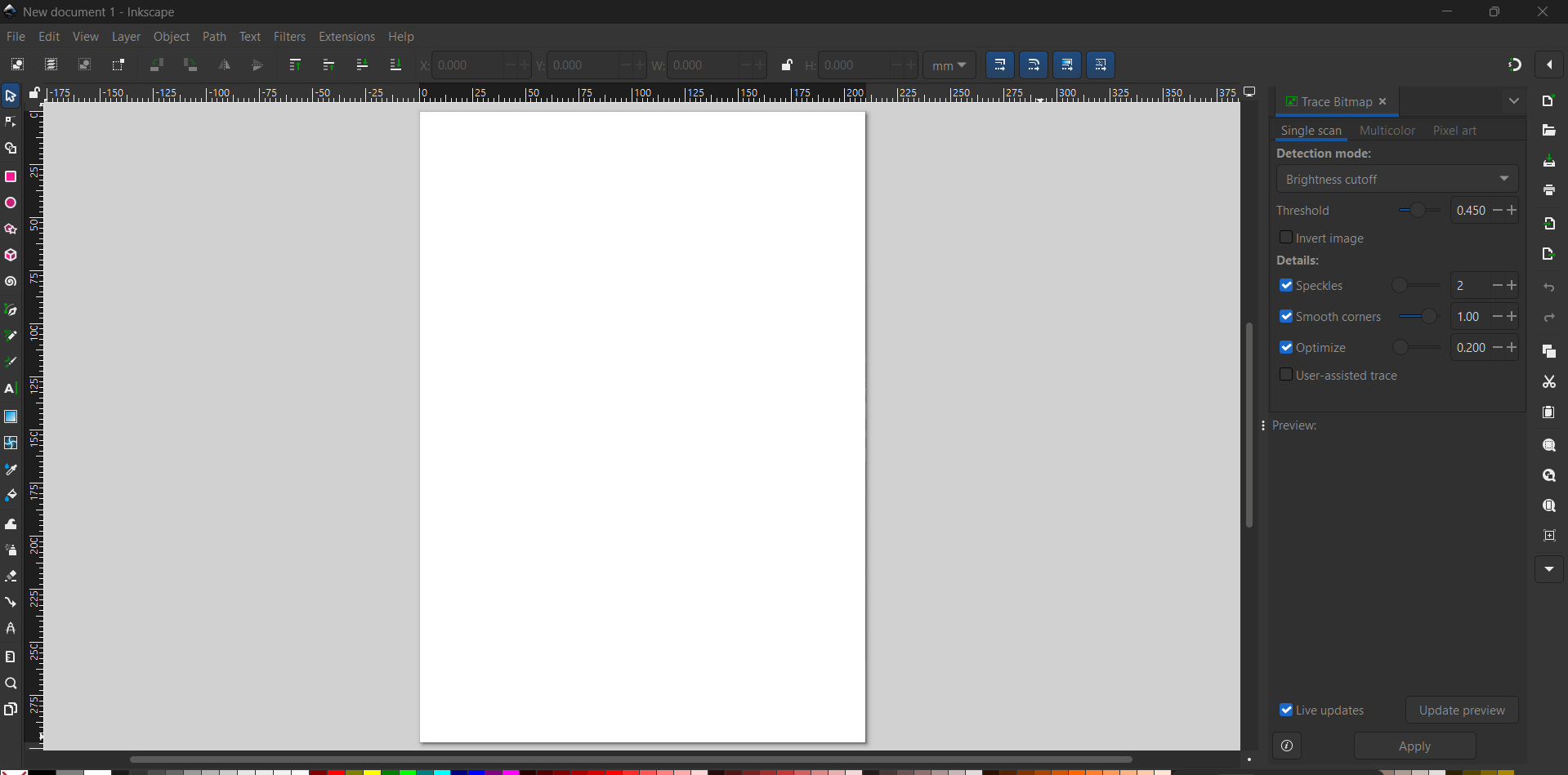
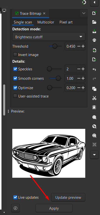
To convert the pixelated raster image into a clean vector graphic, I selected the image and went to Path > Trace Bitmap in Inkscape. This feature generated a vector version of the image by tracing its outlines, allowing me to scale it without losing quality.
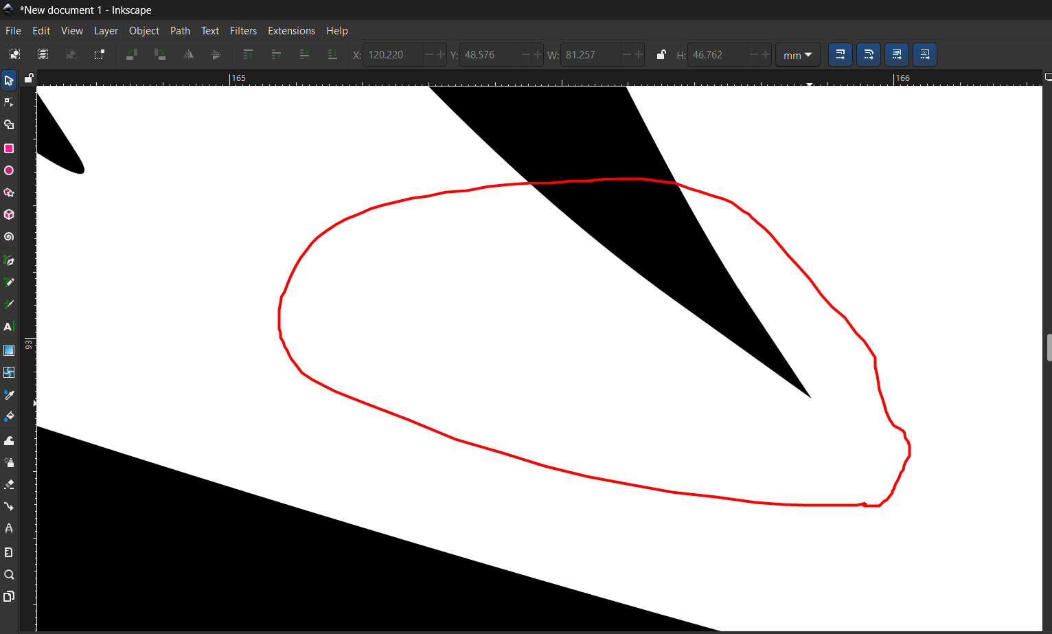
After generating the vector image using the Trace Bitmap tool, I zoomed in closely to inspect the result. Unlike the original raster version, the vector image remained sharp and clear, with no pixelation. This confirmed that the image was now fully vectorized and suitable for precise design or fabrication.
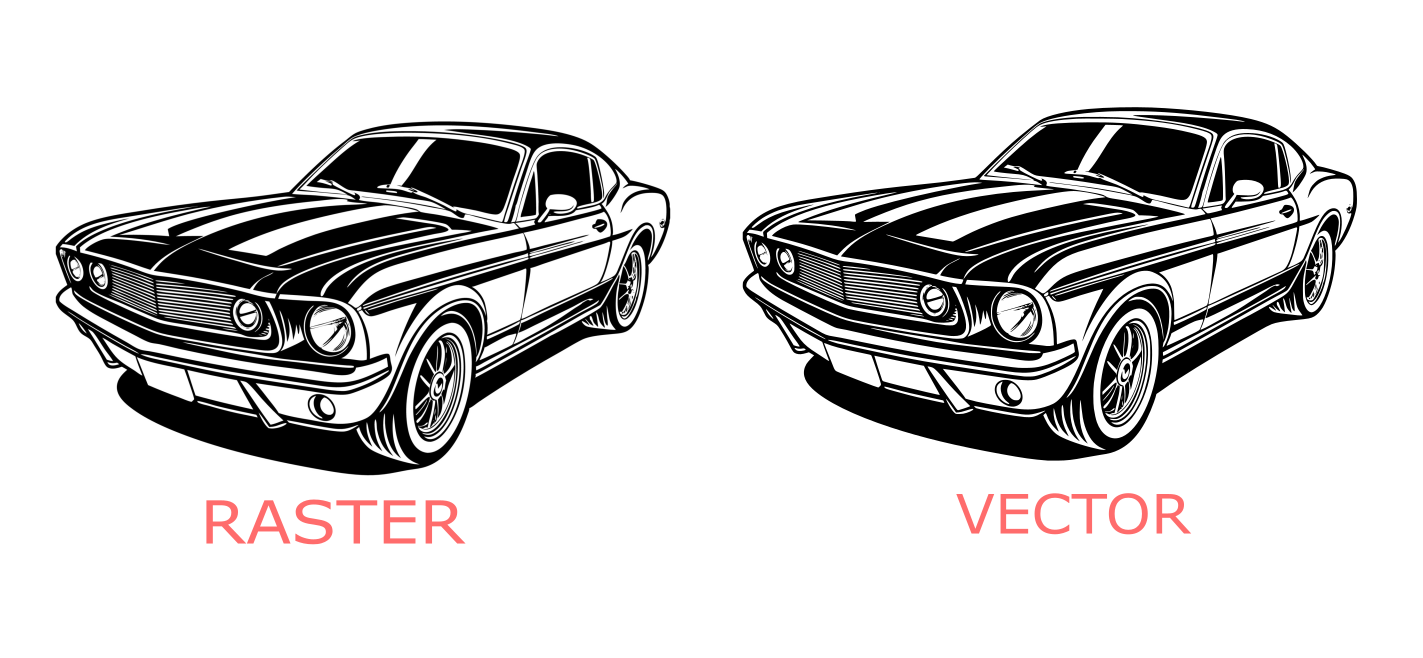
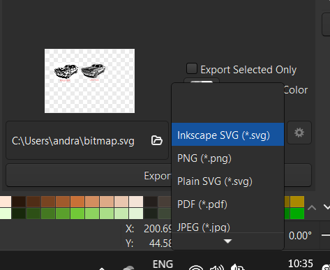
Comparing Raster vs Vector and Saving the File To highlight the difference, I compared the raster image (which became pixelated when zoomed) with the vector version (which remained crisp at all zoom levels). Finally, I saved the vector graphic in SVG format, which preserves scalability and is ideal for digital fabrication and design.
I used the default Windows Photos application. It offers a simple and user-friendly method to resize images without needing any external software.
The image size before compression was around 1 MB.
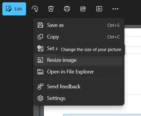
In the Windows Photos application, I clicked on the “See More” option (three dots) located at the top-right corner. From the dropdown menu, I selected “Resize”. This opened the resizing options, allowing me to easily adjust the image dimensions to reduce the file size as needed.
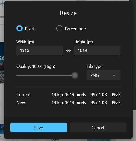
When I entered the Resize option in Windows Photos, it initially displayed the settings in pixels, showing the width (W) and height (H) values. It also allowed me to choose the file type, such as JPEG, helping me control both the image size and format efficiently.
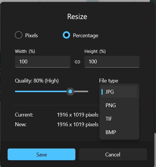
Inside the Resize option, I switched the unit from pixels to percentage for easier scaling. I also changed the file type to JPEG. By default, it set the size to 80%, providing high-quality compression. If needed, I could adjust the percentage further to control the file size.
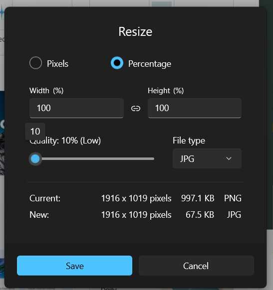
Since Fab Academy limits a single Git push file size to 10 MB, I compressed the image further by setting the resize percentage to 10%. After this compression, the final image size was approximately 67.5 KB, making it well within the allowed limit for uploading.
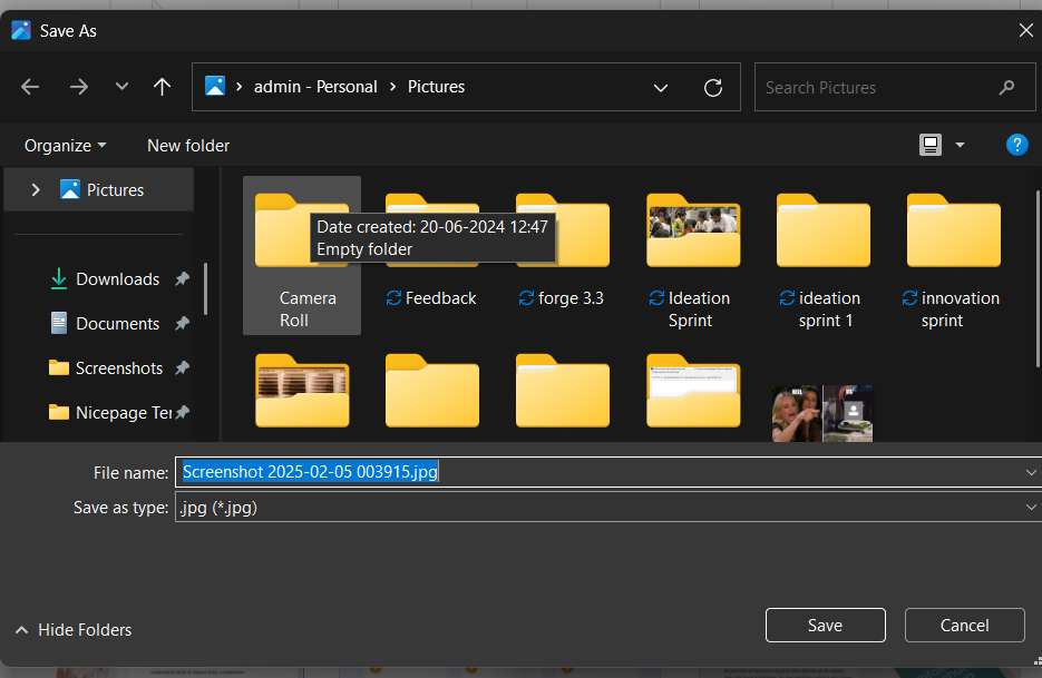
After resizing and compressing the image, I saved it according to my requirements. I selected the appropriate file name and specified the location on my computer for easy access. This ensured the image was ready for upload and stored in a convenient folder for future reference.
In this section, I explored video processing techniques to reduce file size and optimize video quality for uploading. For this task, I used HandBrake is a free and open-source video transcoder used for converting and compressing video files. It supports a wide range of input formats and offers tools to adjust video quality, resolution, and file size. HandBrake is especially useful for preparing videos for web uploads and limited storage environments.
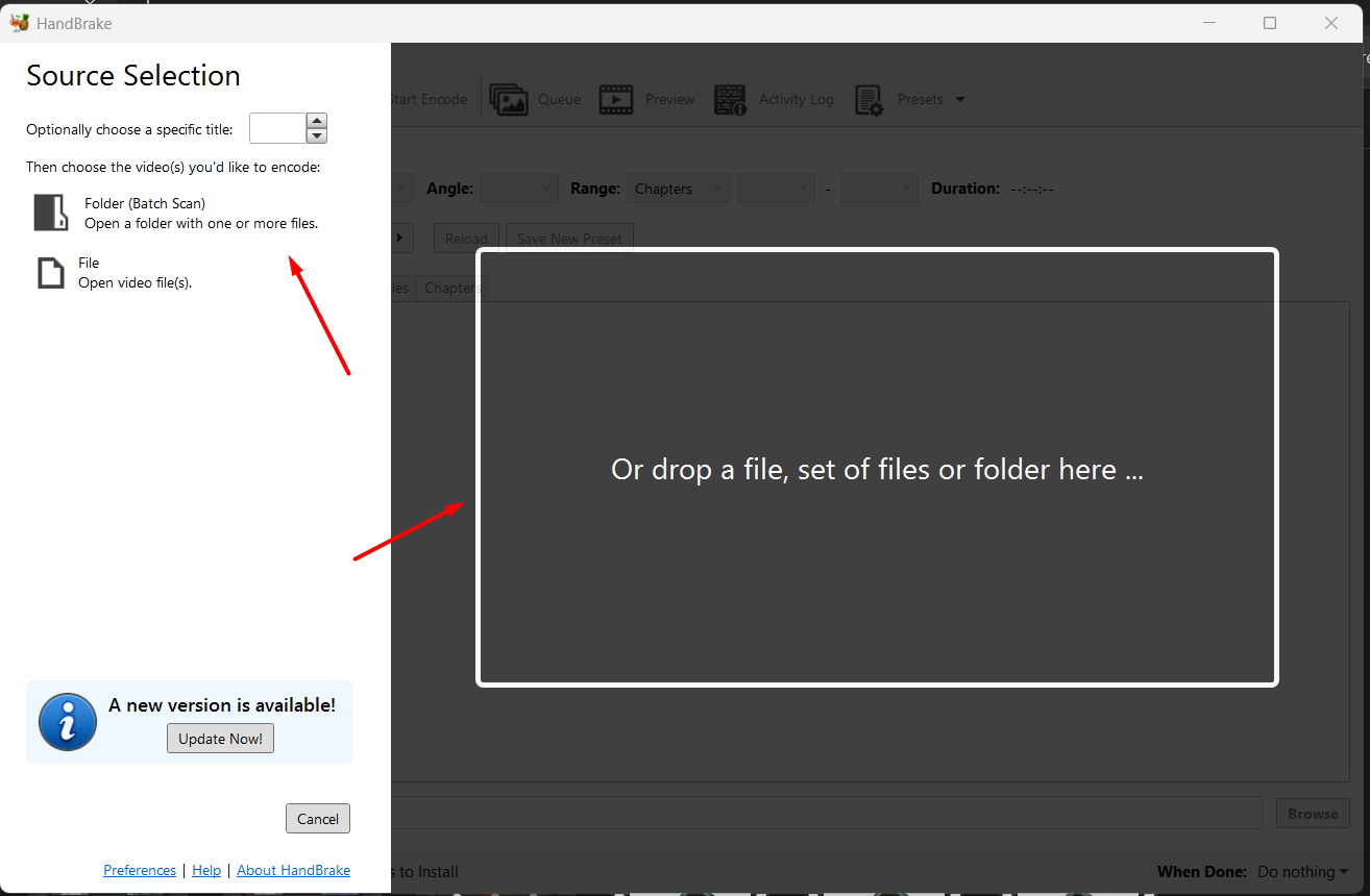
Uploading Video in HandBrake Once HandBrake is opened, the first step is to upload the video file you want to process. There are two simple options: you can either drag and drop the video file directly into the interface, or use the “File” option to browse and select the desired video manually.
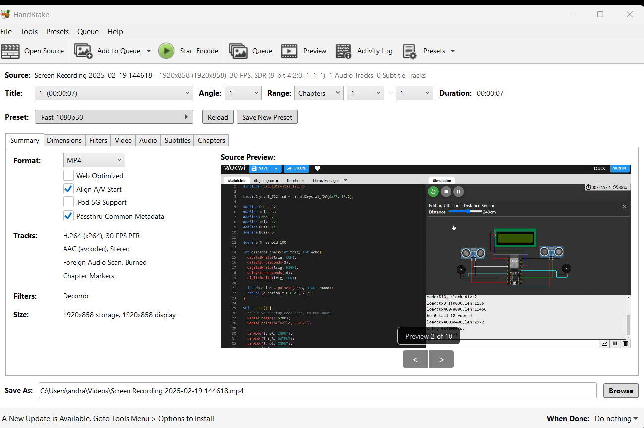
For testing, I selected a 25-second video file with an initial size of 25 MB. The video had a frame width of 1920 pixels and a frame height of 878 pixels, which corresponds to high-definition resolution. These values were displayed in HandBrake upon loading the video file.
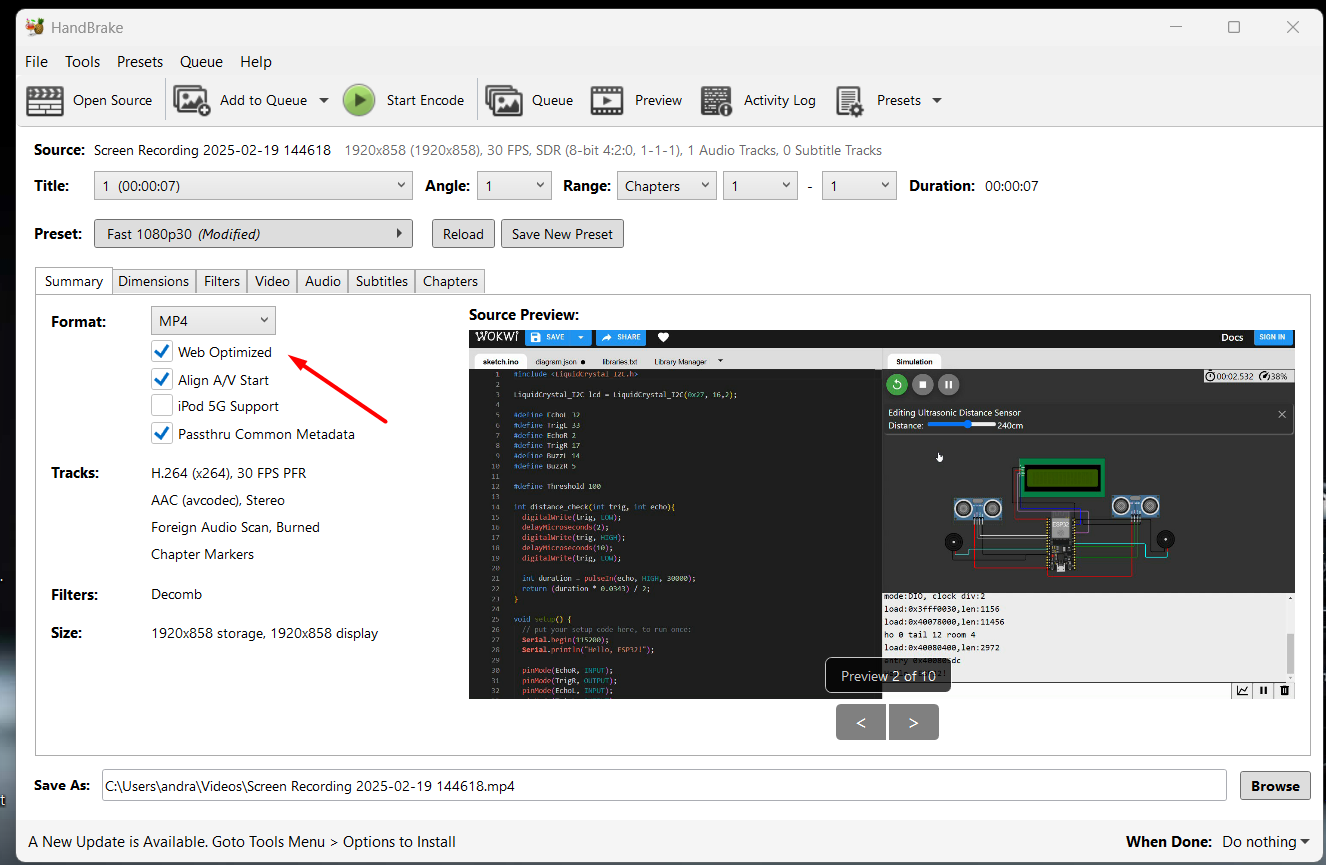
After loading the video, I selected the default preset: Fast 1080p30, which maintains good quality while ensuring quicker processing. I chose the MP4 format for wide compatibility and enabled the “Web Optimized” option to make the video better suited for online streaming and faster loading on web platforms.
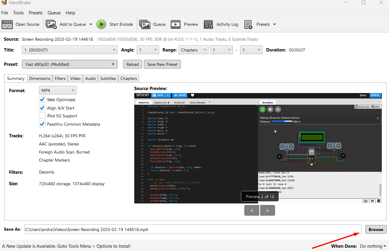
After selecting the desired settings and format, I set the output location to save the processed video file. Once the destination was confirmed, I clicked the “Start Encode” button. HandBrake began compressing the video based on the selected preset, optimizing it for size and web compatibility
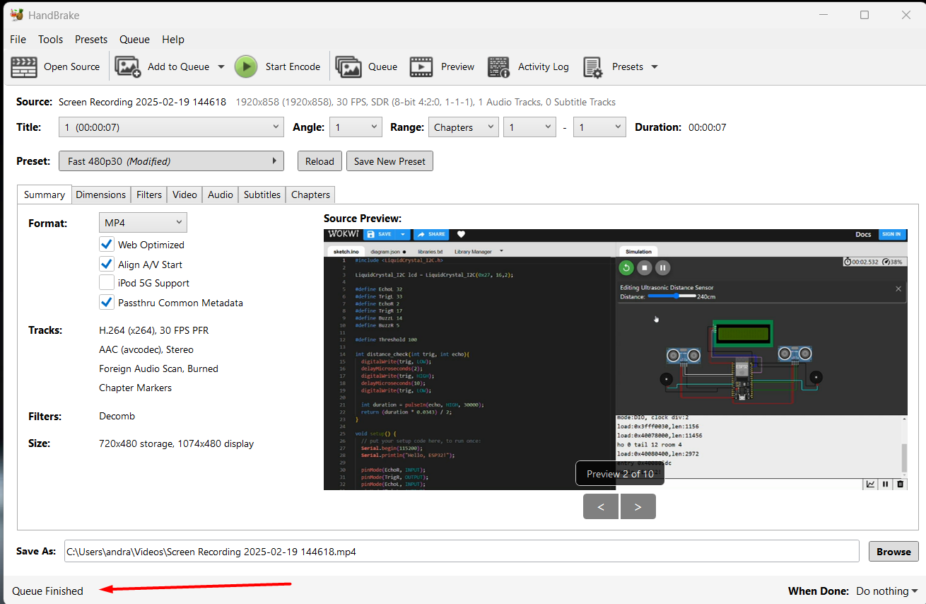
Once the encoding process was complete, HandBrake displayed a “Queue Finished” message at the bottom of the window. This confirmed that the video had been successfully processed and saved to the specified location. The new file was now optimized in size and ready for uploading or sharing.
The final processed video had a reduced file size of just 1 MB, while maintaining the same frame dimensions of 1920 × 872 pixels. This shows how effective HandBrake is at compressing video without significant quality loss, making it ideal for storage-efficient and web-friendly video sharing.
For the Computer-Aided Design (CAD) week, I chose to work with Fusion 360 and Onshape. Both are powerful 3D modeling tools. Fusion 360 offers strong design and simulation capabilities, while Onshape provides cloud-based modeling. Exploring both platforms helped me understand different workflows and design environments.
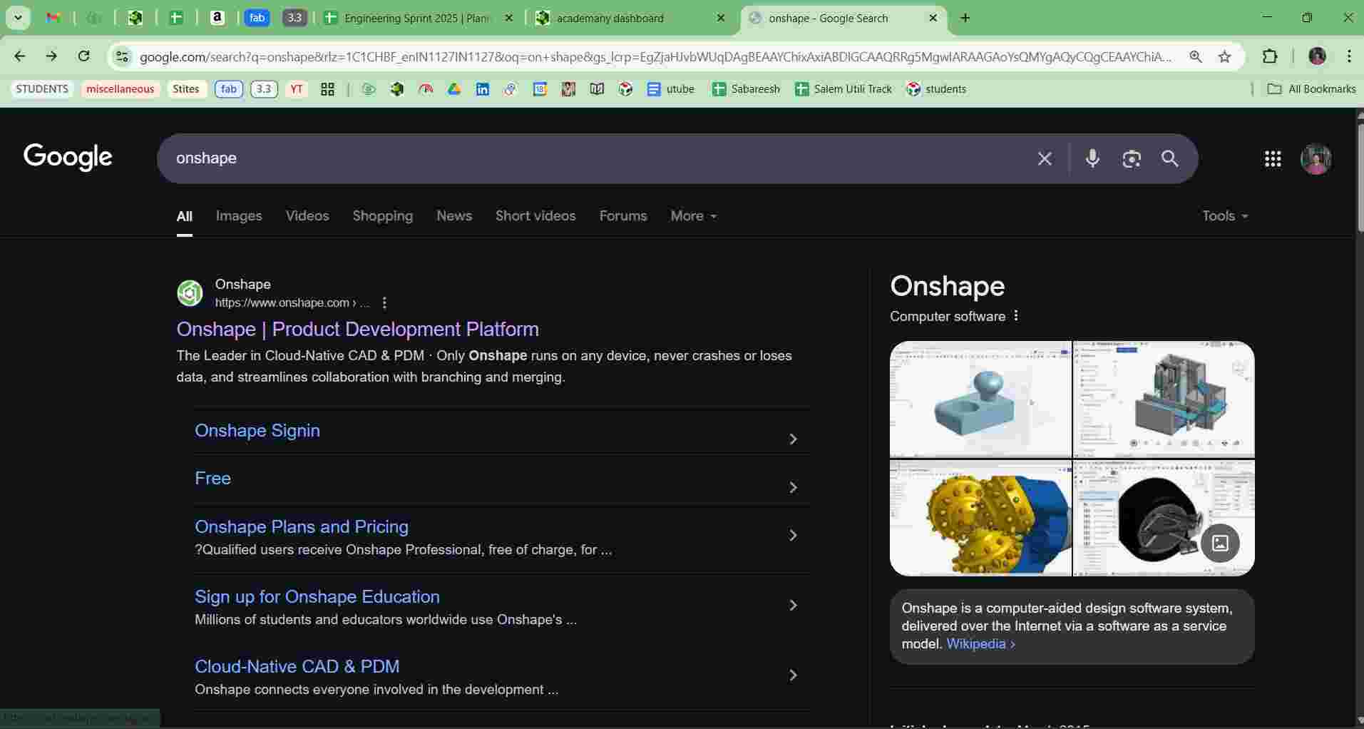
Accessing Onshape via Google Search and Logging In
To access Onshape, I performed a Google search for "Onshape" and clicked on the official website link. On the homepage, I selected the “Sign In” option. I then entered my login credentials to access the Onshape dashboard, where I could start creating and managing my CAD projects.
Selecting 2D Sketch and Choosing Planes
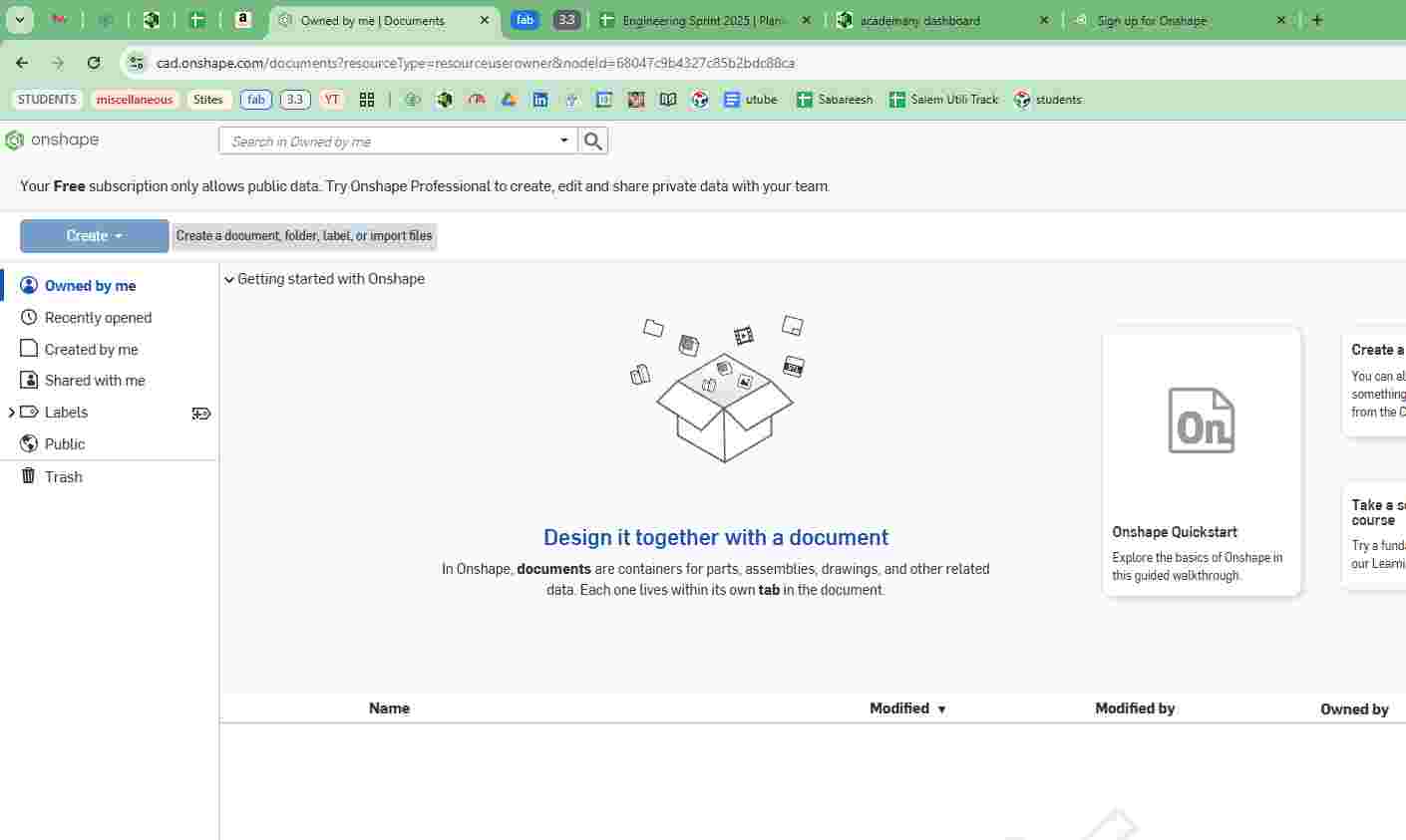
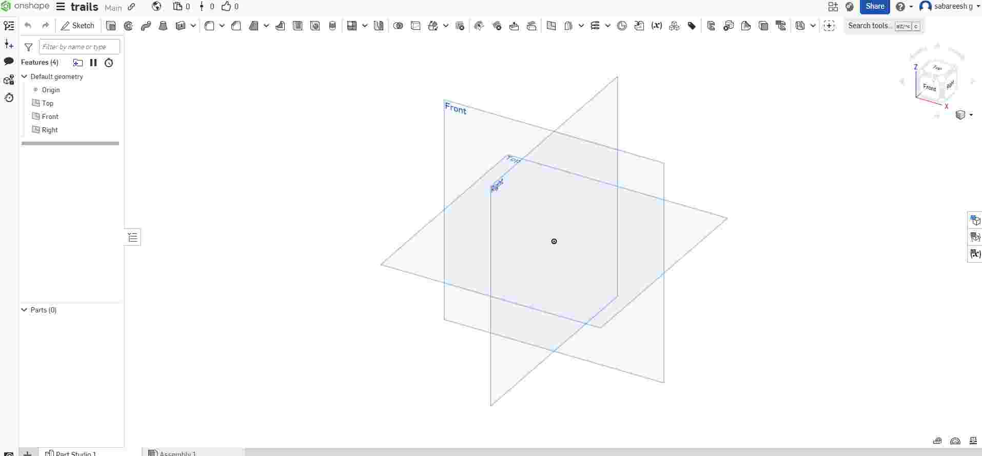
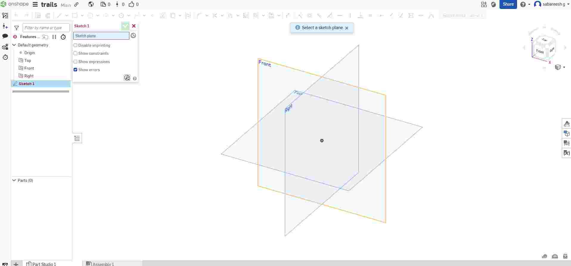
In Onshape, to start a 2D sketch, I first clicked on the “Sketch” tool. The software then prompted me to select a plane. I chose from the default planes — Top, Front, or Right — depending on the orientation needed for my design, and then began sketching.
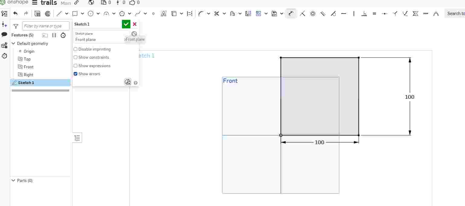
I selected the Front Plane in Onshape to create my 2D sketch. After selecting the plane, I sketched a rectangle and used the Dimension tool to set its width (W) to 100 mm and breadth (B) to 100 mm, ensuring accurate size for the base shape.
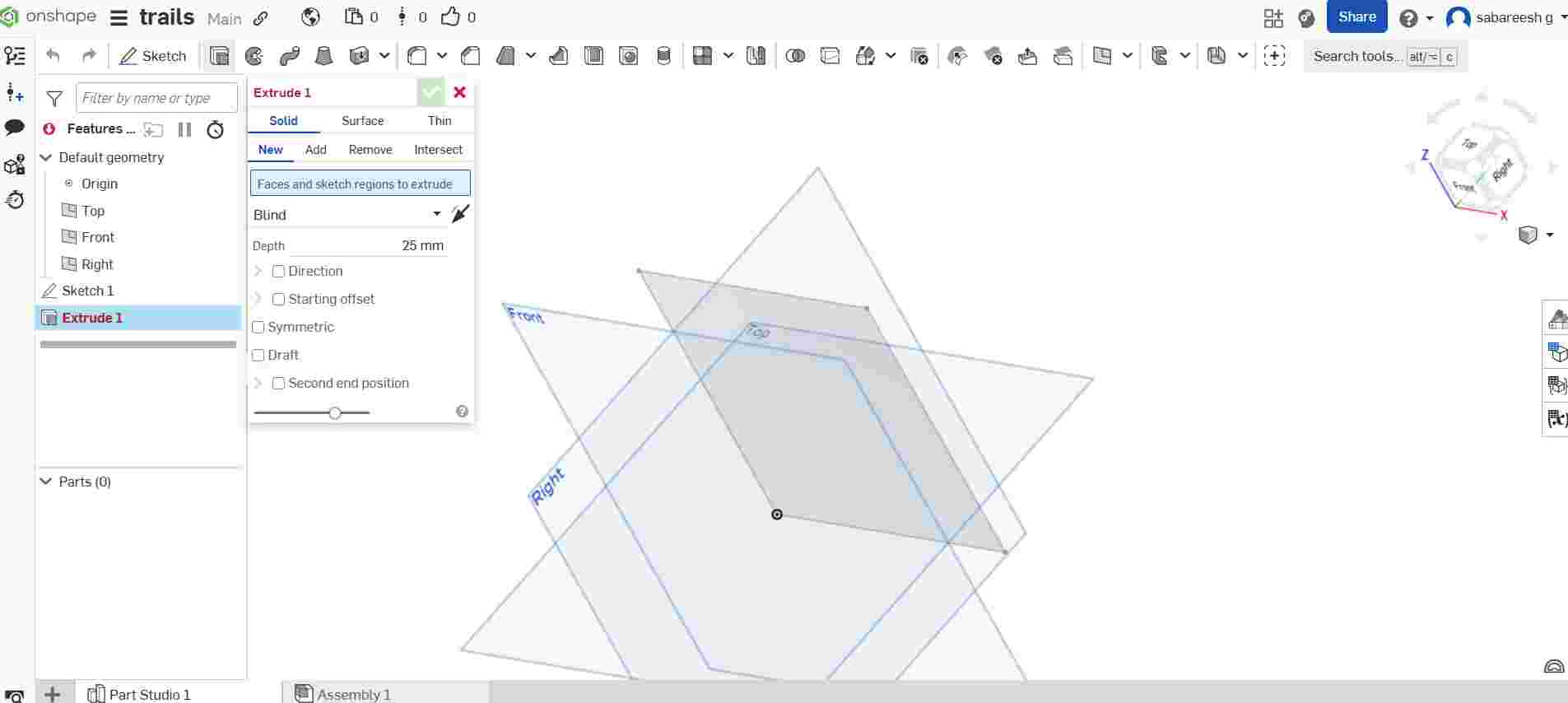
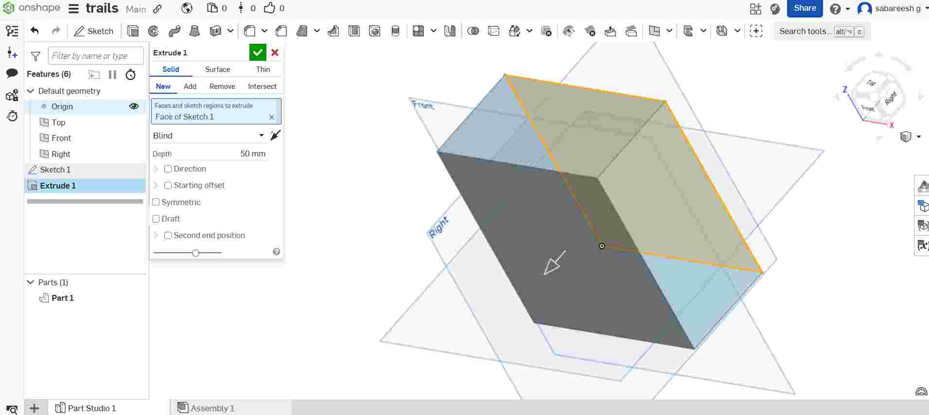
After completing the 2D sketch on the Front Plane, I selected the closed profile by clicking inside the shape. Then, I used the Extrude tool to give the sketch a 3D form. I entered the desired extrusion distance, converting the flat sketch into a solid three-dimensional object.
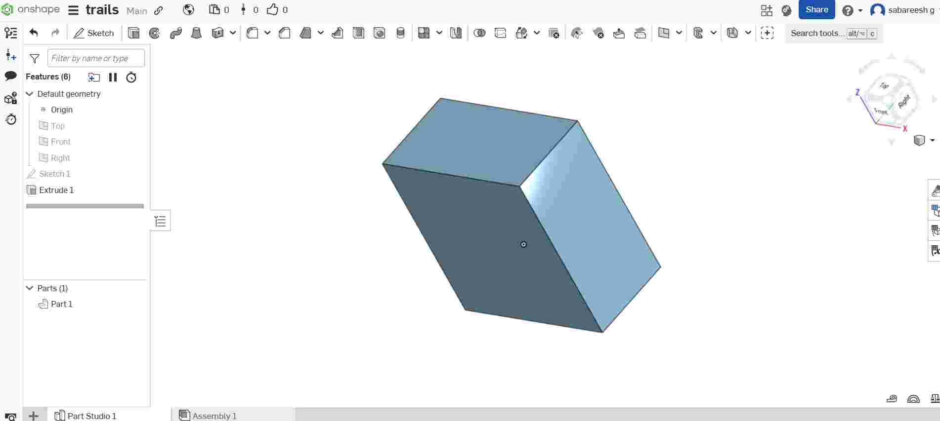
After completing the 2D sketch on the Front Plane, I selected the closed profile by clicking inside the shape. Then, I used the Extrude tool to give the sketch a 3D form. I entered the desired extrusion distance, converting the flat sketch into a solid three-dimensional object.
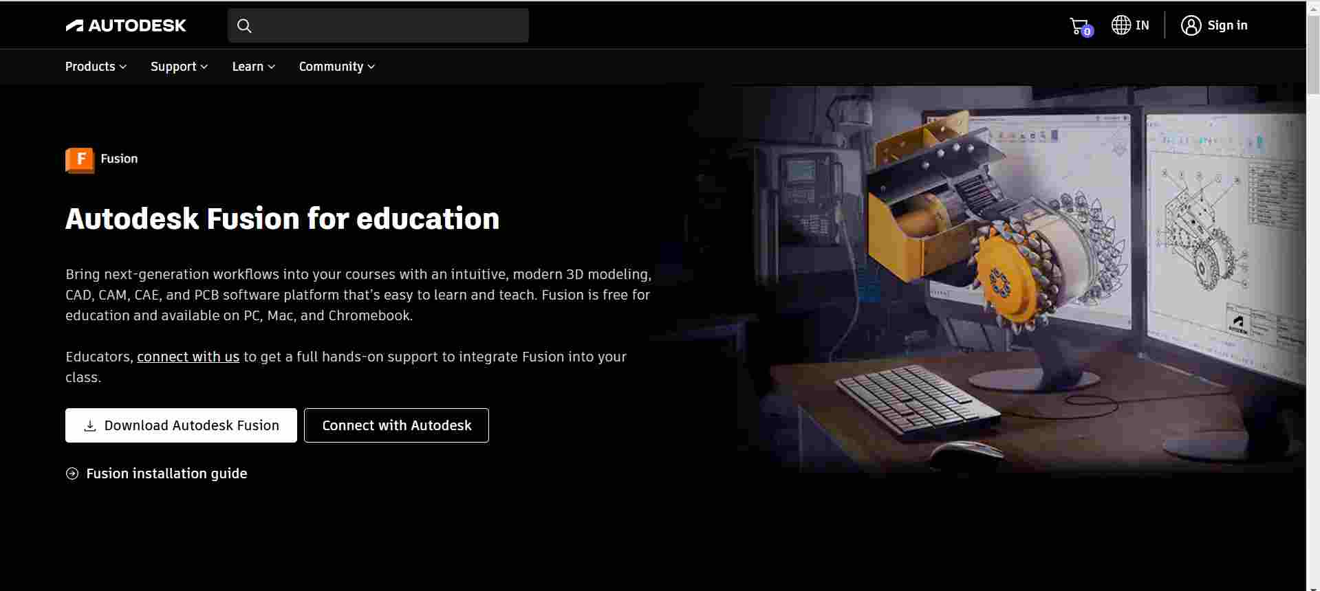
Fusion 360 download and installation link
To download and install Autodesk Fusion 360, visit the official Autodesk Fusion 360 free trial page:
Autodesk
This page provides access to a 30-day free trial of Fusion 360, allowing you to explore its full capabilities. After the trial period, you can choose from various licensing options
License: Free for non-commercial projects, ideal for hobbyists and makers.
Educational License: Free for students and educators.
Autodesk
Ensure you select the appropriate license that fits your needs. The installation process is straightforward, and the website provides step-by-step guidance to help you get started with Fusion 360.
Install the Fusion 360
To begin working with Fusion 360, the first essential step is to properly install the software on a computer. Fusion 360 is a powerful 3D CAD, CAM, and CAE tool developed by Autodesk, widely used for product design and development.
I visited the official Autodesk website and created an Autodesk account, which is necessary to access Fusion 360. After signing in, I selected the appropriate version suitable for my system specifications and downloaded the installer.
Once the download was complete, I launched the installer and followed the on-screen instructions to complete the installation process.
During the installation, I ensured that my system met the minimum hardware and software requirements to avoid compatibility issues. After the setup was complete, I opened Fusion 360, signed in with my Autodesk credentials, and verified that the software was activated successfully.
Now, Fusion 360 is ready for use, and I can start designing and creating 3D models as part of my project work.
Opening Fusion 360
After successfully installing Fusion 360, I proceeded to open the application. I located the Fusion 360 icon on my desktop and double-clicked it to launch the software. Upon opening, Fusion 360 prompted me to sign in using my Autodesk account credentials. I entered the login details that I had created during the download process.
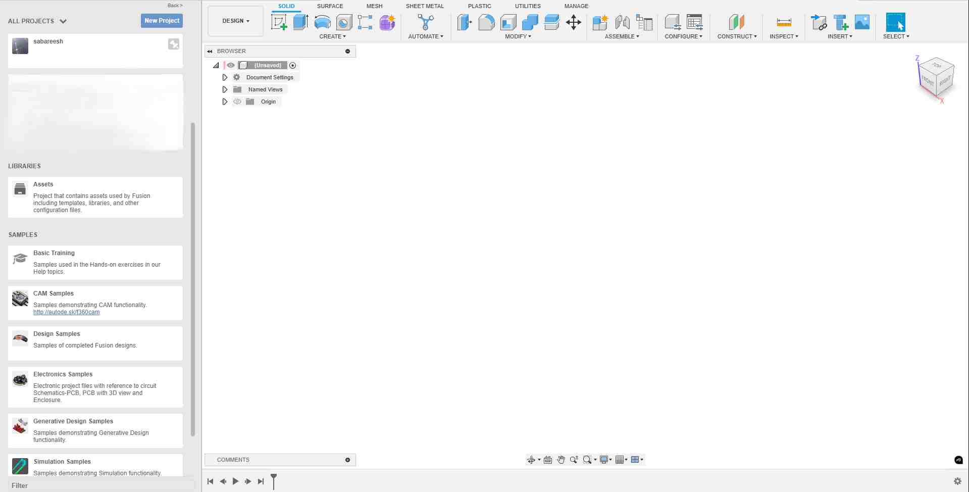
Once logged in, the Fusion 360 user interface loaded completely. The workspace displayed several design environments such as Design, Render, Animation, Simulation, and Manufacture, offering a wide range of tools for different stages of product development.
At the first launch, I also reviewed the default settings, ensuring that the unit system was set according to my project needs (for example, millimeters or inches). With Fusion 360 successfully opened and ready,
I was now prepared to start creating sketches, 3D models, and prototypes as part of my assignment work.
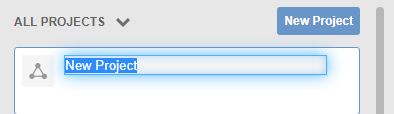
Creating a New Project in Fusion 360
After opening Fusion 360, I created a new project to organize my work. I clicked the Data Panel, selected “New Project”, and entered a suitable name. This helped me keep all related design files in one place, making it easier to manage and track my assignment progress.
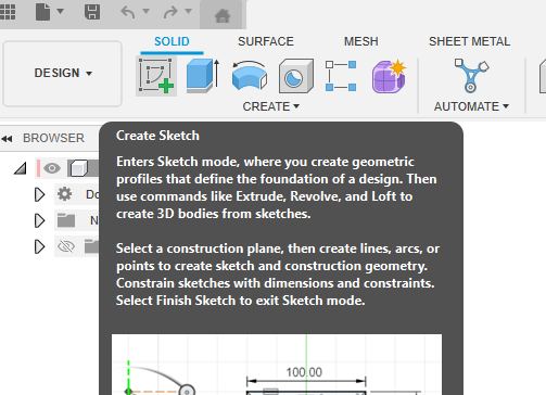
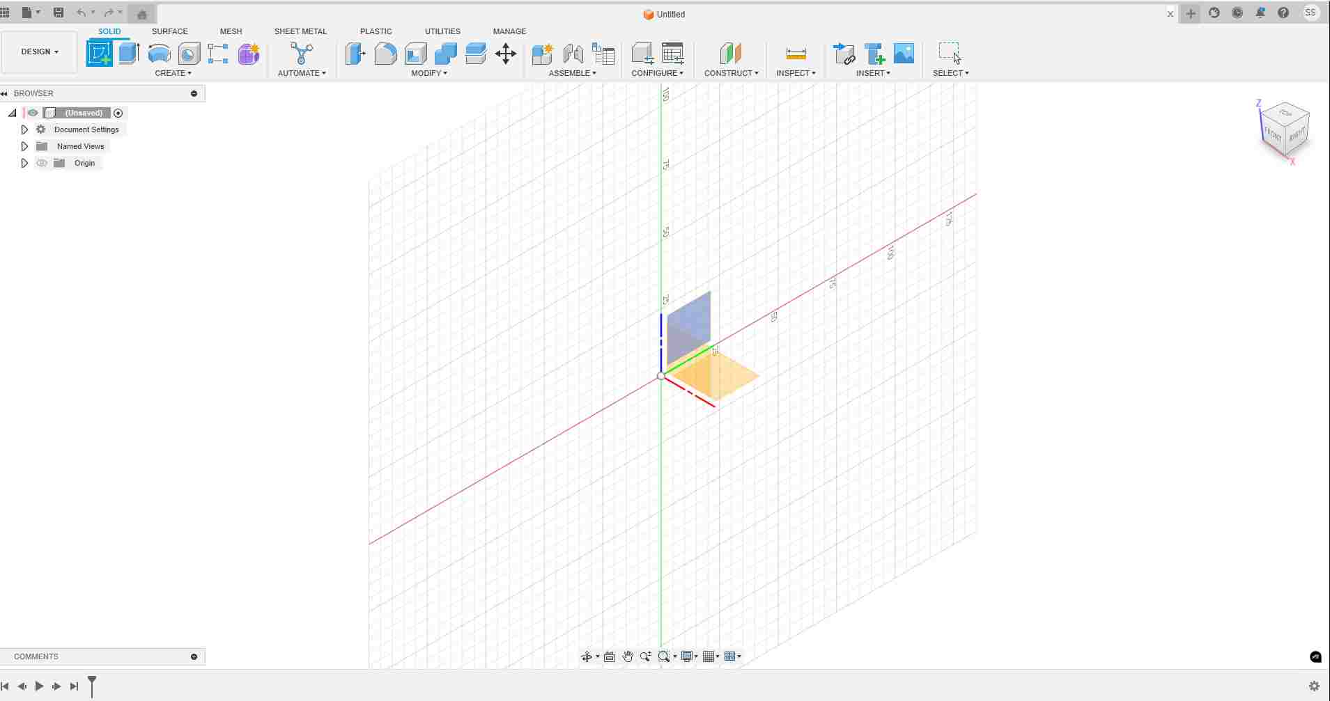
Clicking Sketch in Fusion 360
To start designing, I clicked on the “Create Sketch” option available in the toolbar. This allowed me to begin a 2D drawing on a selected plane. Sketching is the foundation for creating 3D models, and it provided a workspace where I could draw basic shapes like lines, circles, and rectangles.
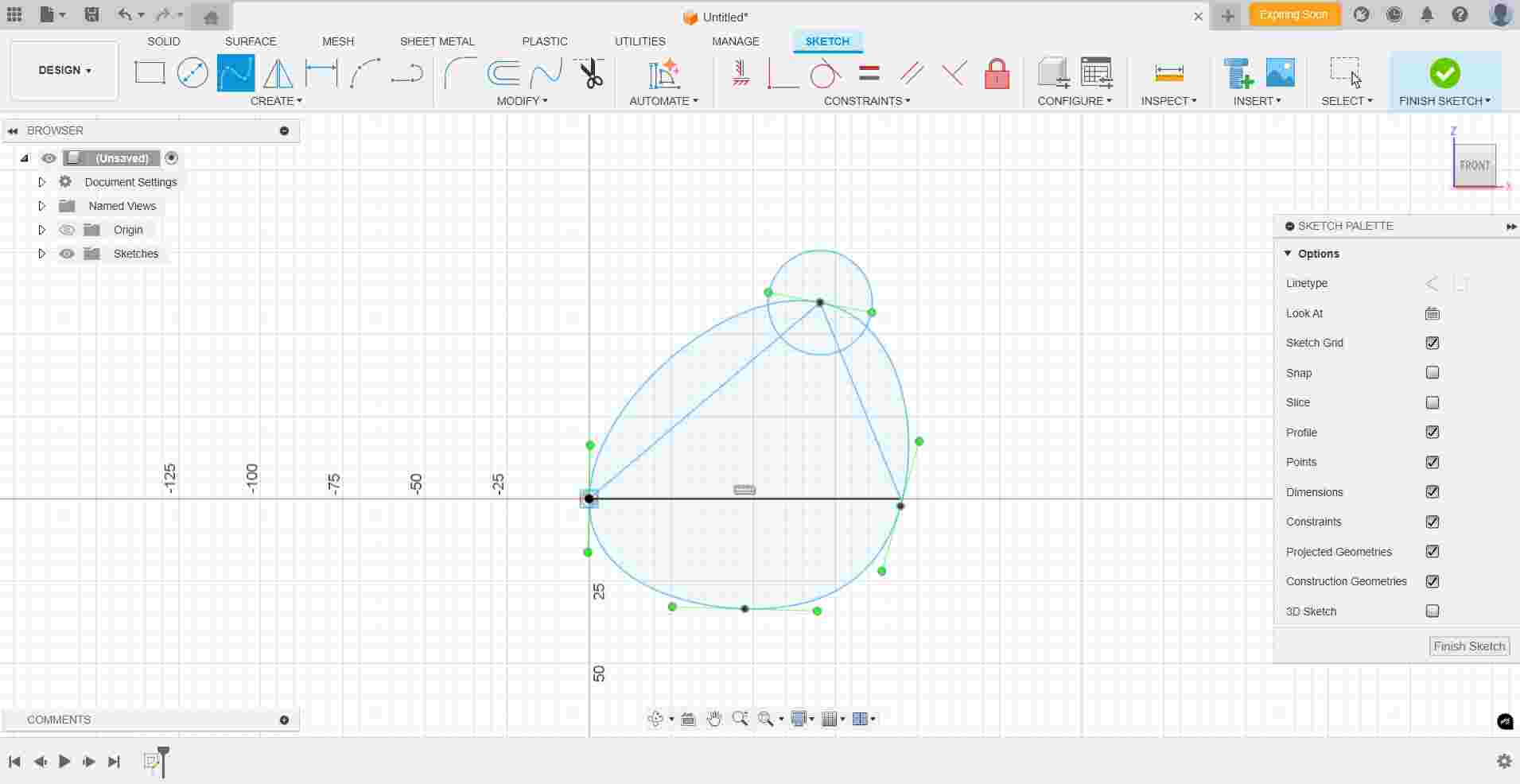
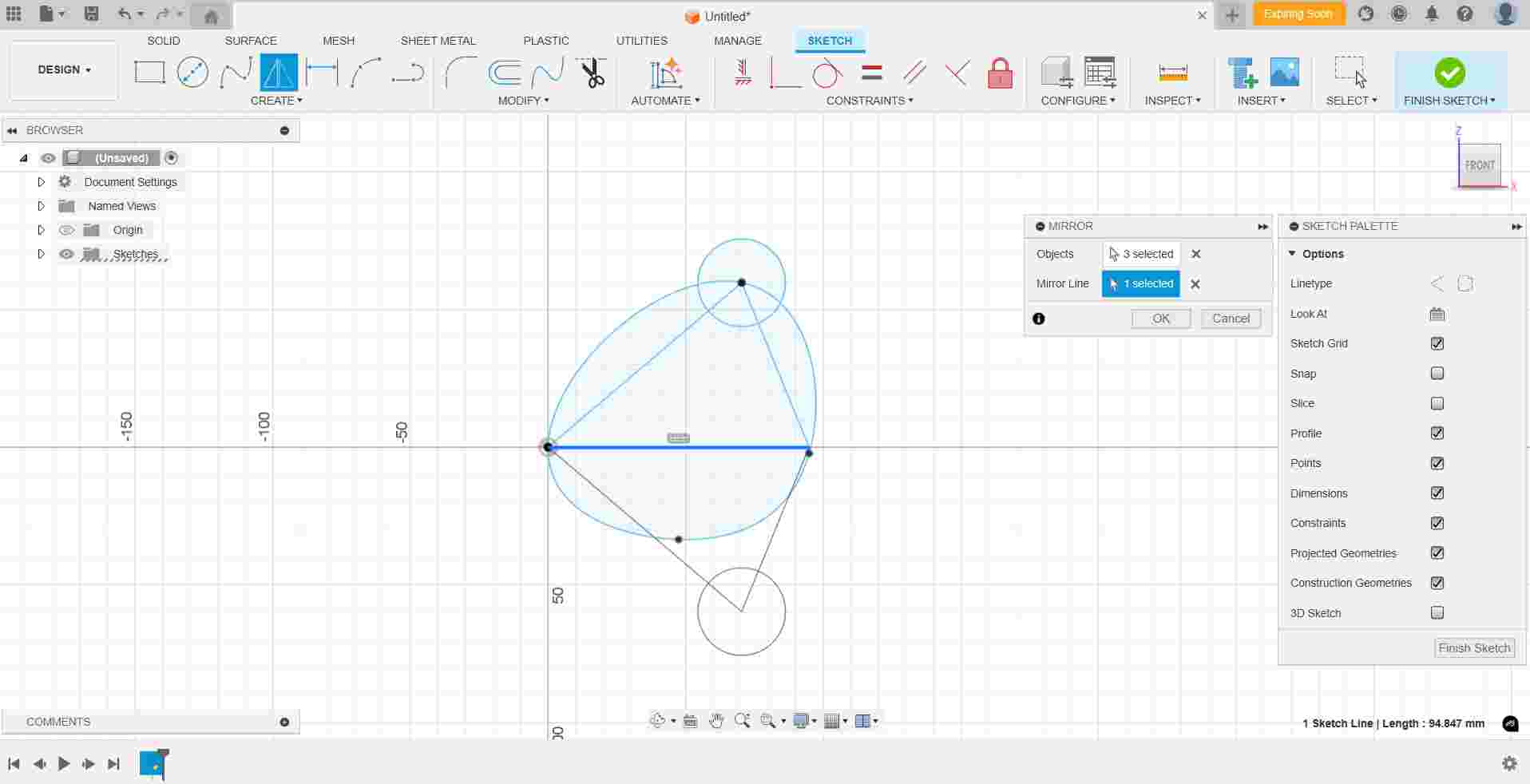
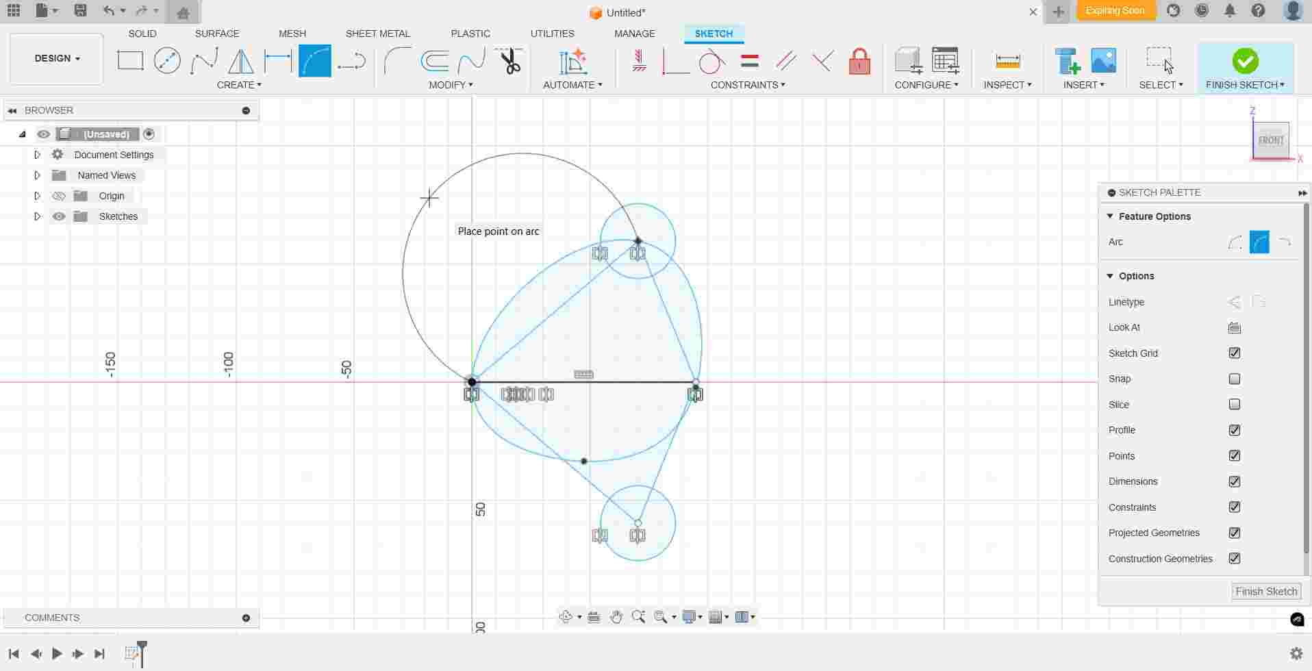
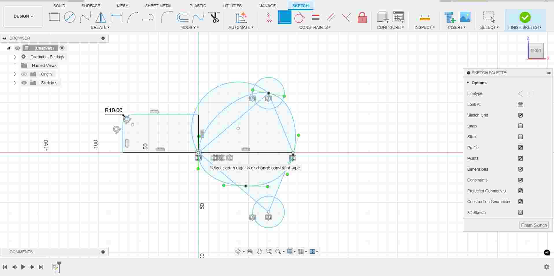
Sketching with Line, Spline, Circle, Rectangle, Dimension, Fillet, Arc, and Mirror Tools
Inside the sketch mode, I explored different tools such as Line, Spline, Circle, and Rectangle to create basic shapes. I also used Dimension to set exact sizes, applied Fillet to round corners, drew curves with Arc, and used Mirror to duplicate shapes symmetrically.

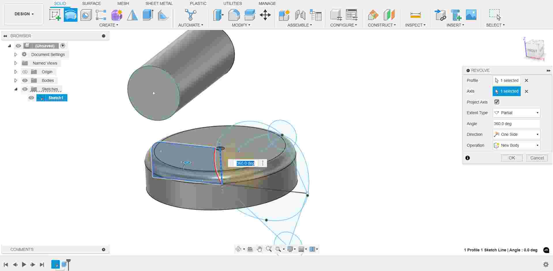
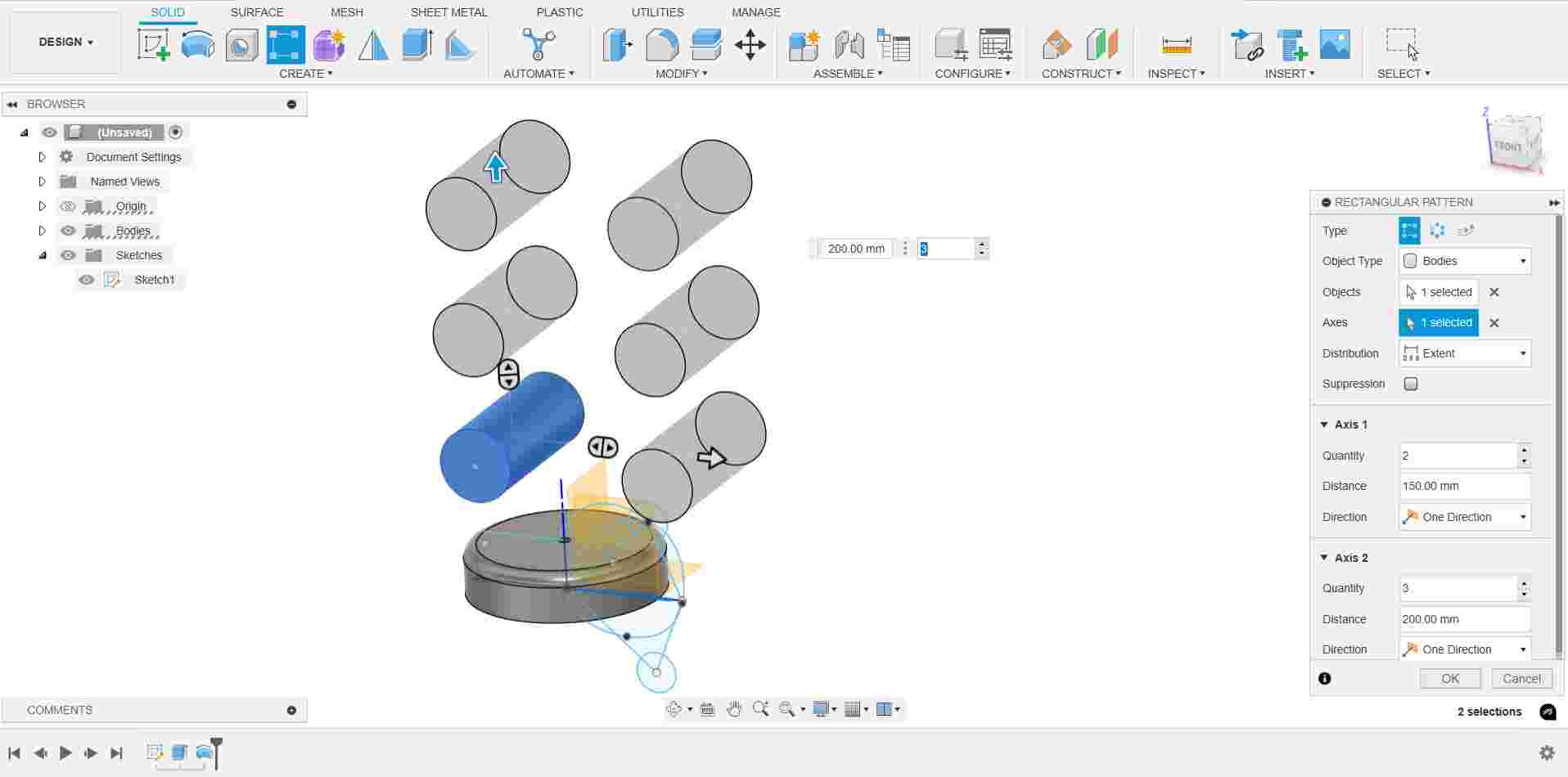

Using Extrude with Dimension, Revolve, Rectangular Pattern, and Chamfer
After finishing the sketch, I used Extrude with specific dimensions to convert 2D sketches into 3D models. I also applied the Revolve tool to create objects by rotating profiles. Then, I explored the Rectangular Pattern to duplicate features and used Chamfer to bevel sharp edges for a clean finish.
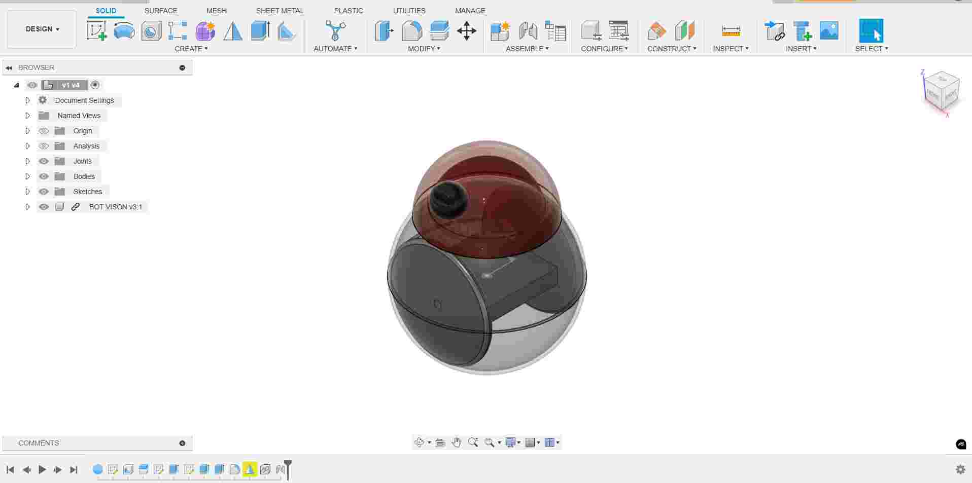
Rough Model of My Final Project
After sketching, I created a rough 3D model of my final project using basic tools in Fusion 360. This early model helped me understand the overall structure, dimensions, and component placement. Although not highly detailed, the rough model gave a clear idea of how the final design would look.
This is the initial version of my design. While it captures the basic concept, it still requires further refinement and iteration to improve functionality, aesthetics, and precision. Based on feedback and testing, I plan to make necessary adjustments in future versions to achieve a more optimized final outcome.