Group assignment
Individual assignments

1. Read this manual carefully before operating machine.
2. This is class IV CO2 Laser, which can be harmful in direct contact with body or from mirror
reflection to body. So be careful before operating it.
3. Do give 230 VAC 1 Phase 2 wire supply with proper earthing (Voltage between neutral and
earth should be less than 2V).
4. This machine has optical parts, which may tend, may go bad due dust, fumes and moisture.
Please keep your machine in clean dust free environment with humidity below 80% noncondensing.
5. Provide adequate exhaust duct to remove fume from the area where machine is kept.
6. Please note optics has no warranty so take appropriate care.
7. Don’t run the machine without air in nozzle as might spoil lens.
8. Kindly check chiller temperature regularly. The chiller temperature should not be above 35°C
maximum & min temperature to be maintained is 25°C.
9. This machine has high voltage, and it is mandatory to have proper earthing for the machine
as well as for the personal computer.
10. UPS is mandatory for the machine.
11. Kindly use oil for the slide regularly singer oil is suitable for the machine.
12. Kindly use ethanol for cleaning optics.
13. Refer the fault finding chart for any kind of panel problem.
14. If still you face any problem please contact us on the toll free numbers given in last page.
15. Don’t run the machine without exhaust.
16. If you are not experienced with alignment of optical path please don’t touch any screws of
the optic mechanical parts of the machine.
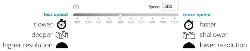
Core Concept of Laser Cutting
In laser cutting, understanding the relationship between laser speed and cut quality is essential. When the laser moves at a slower speed, it cuts deeper and produces higher resolution. In contrast, at a faster speed, the cut becomes shallower with lower resolution, affecting the precision and depth of the output.
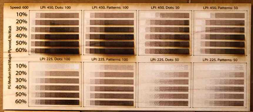
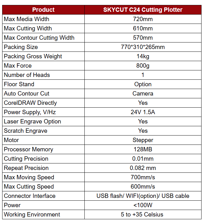
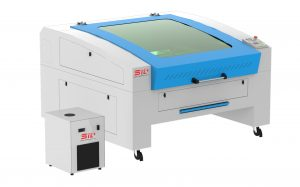
Laser Cutting Machine Settings and Testing
We conducted a basic test using our laser cutting machine to understand how different laser speeds affect cutting performance. By varying the speed settings, we observed changes in cut depth and clarity. This helped us identify the optimal speed for achieving clean, precise cuts in different materials.
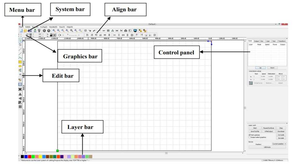
Introduction to RDWorks V8
RDWorks V8 is the software used to operate and control our laser cutting machine. It provides tools for importing designs, adjusting laser parameters like power and speed, and managing layers. RDWorks serves as the interface between our digital design files and the physical laser cutting process.
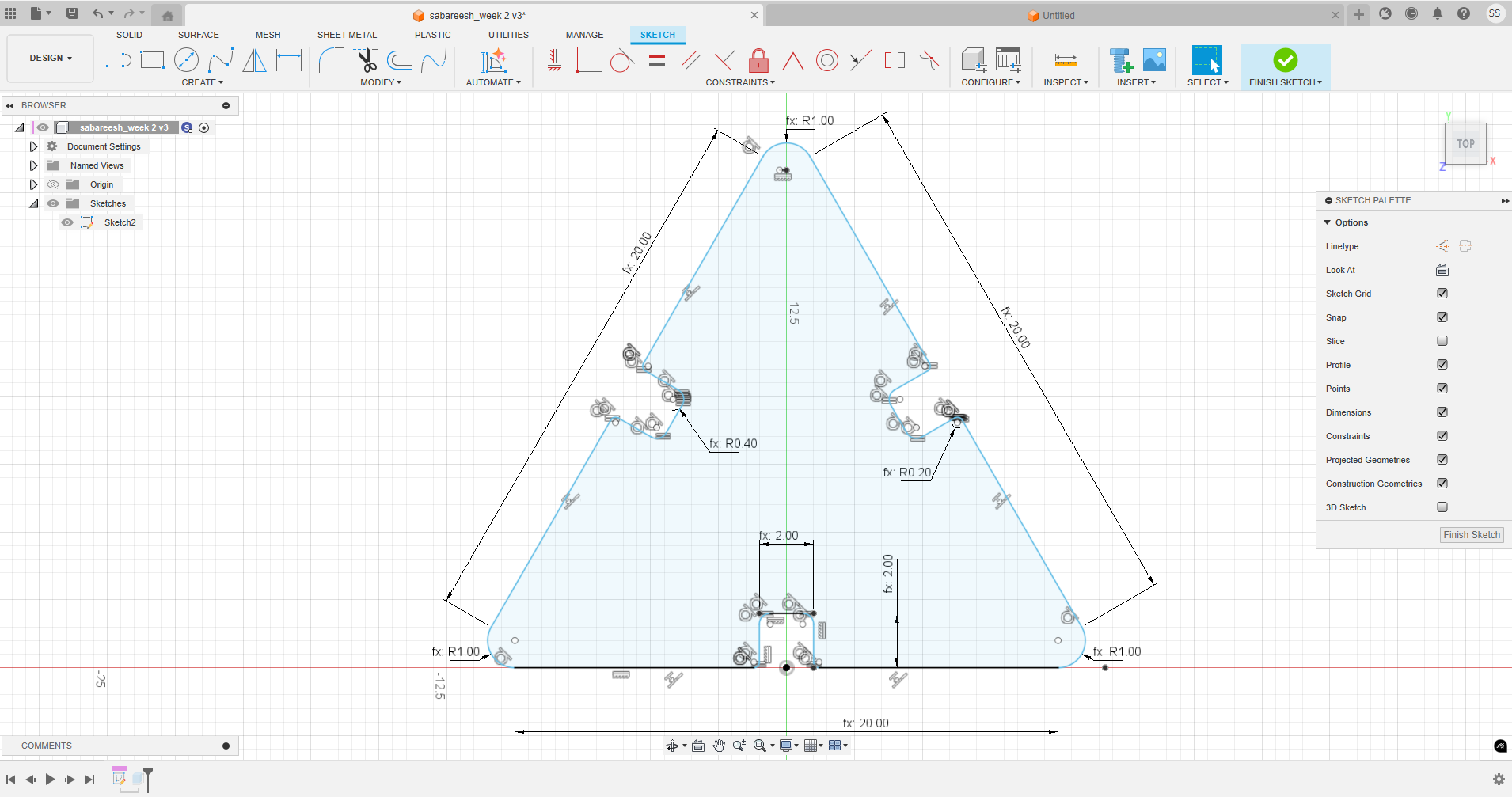
Parametric design in Fusion 360 is a modeling method where dimensions and features are driven by defined parameters (like Length, Width, Thickness). Changes to parameters automatically update the entire model, allowing for flexible and efficient design iterations.
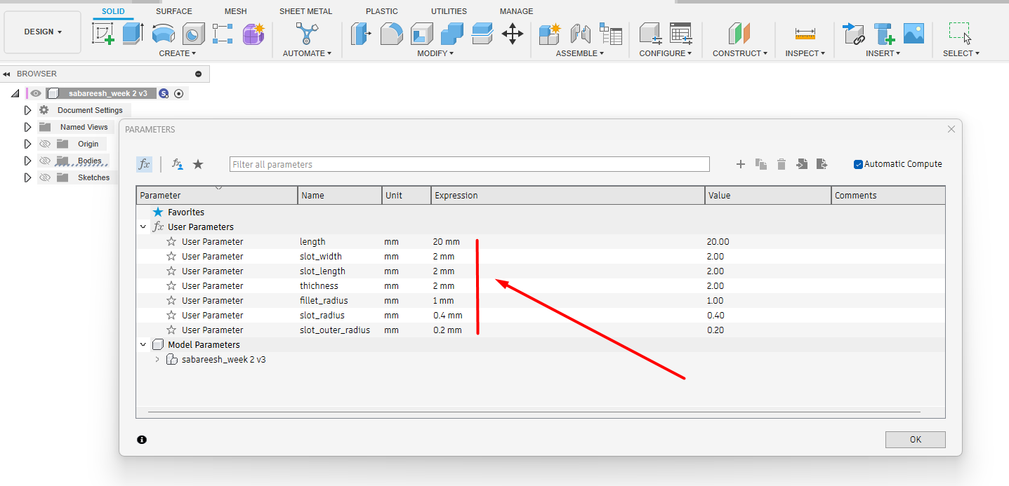
I opened Fusion 360 and navigated to Modify > Change Parameters to define custom values for my design. I added parameters such as length, width, and thickness based on my project requirements. This allowed me to easily update dimensions across the model and maintain design consistency throughout future modifications.
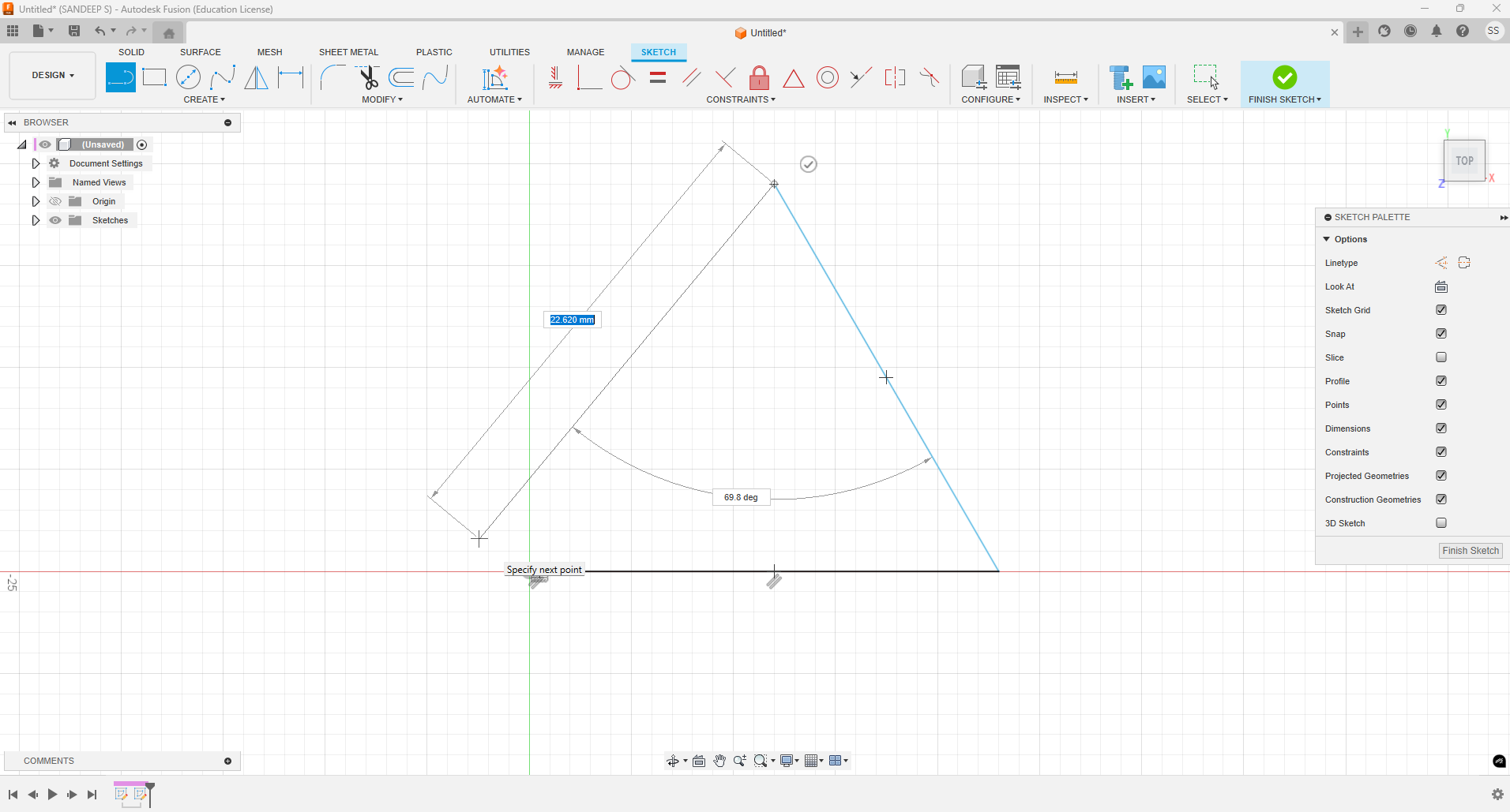
Since I had already decided on the required dimensions, I first added those values in the parameters window. Then, using the line tool within a sketch, I drew a triangle by referencing the defined parameters. This ensured the triangle's sides and angles were accurate and easily adjustable later.
After drawing the triangle, I applied basic dimensions using the parametric values I had defined earlier. Instead of entering fixed numbers, I referenced the named parameters.
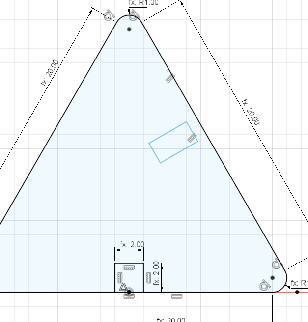
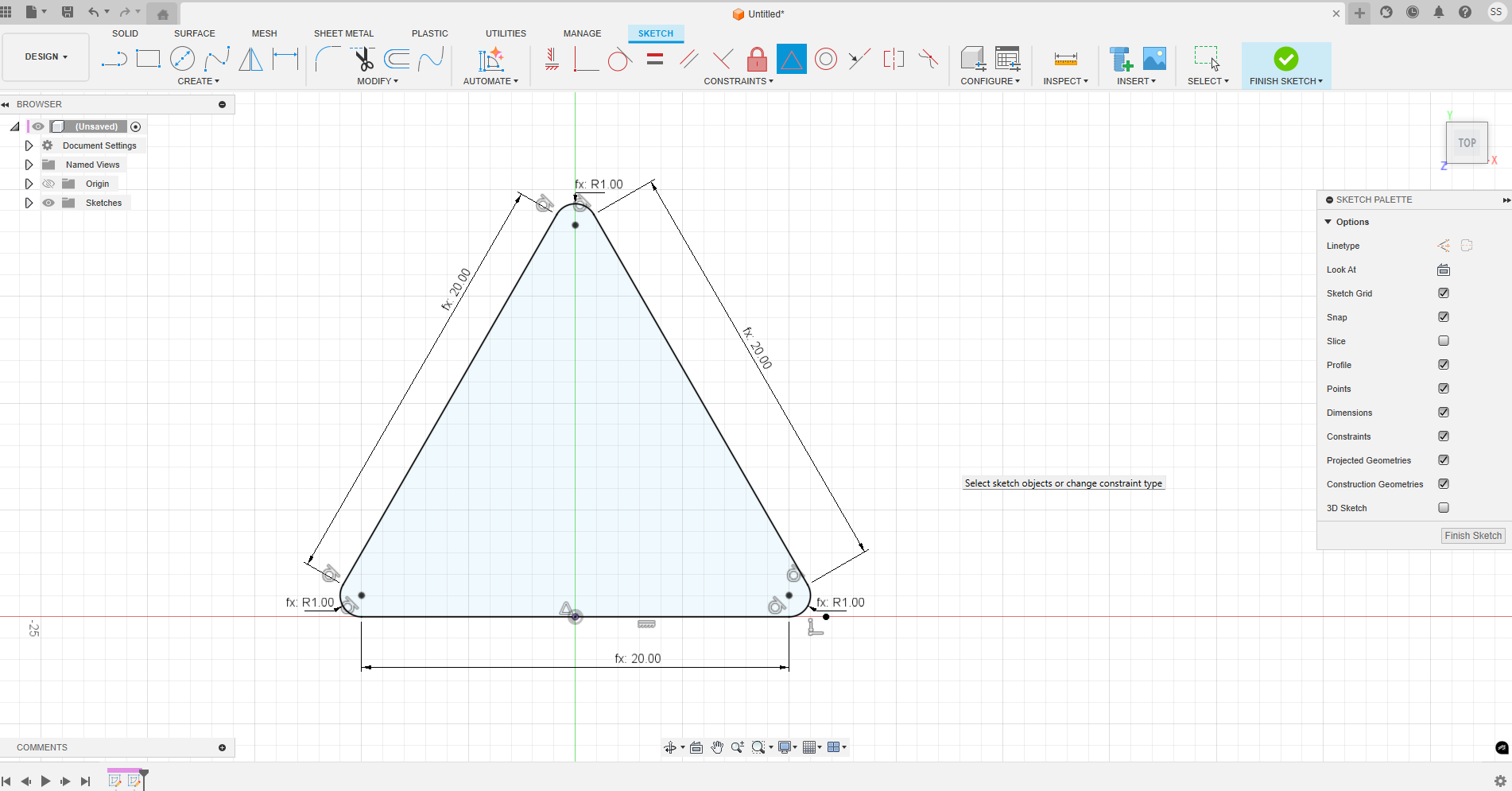
To ensure proper fit and repeatability, I created slots in the design for joints. I used the slot tool and defined all relevant dimensions—such as length, width, and position
As the final step in sketching, I applied fillets to smooth out sharp corners, enhancing both aesthetics and structural integrity. Using the fillet tool, I specified the radius as a parametric value,
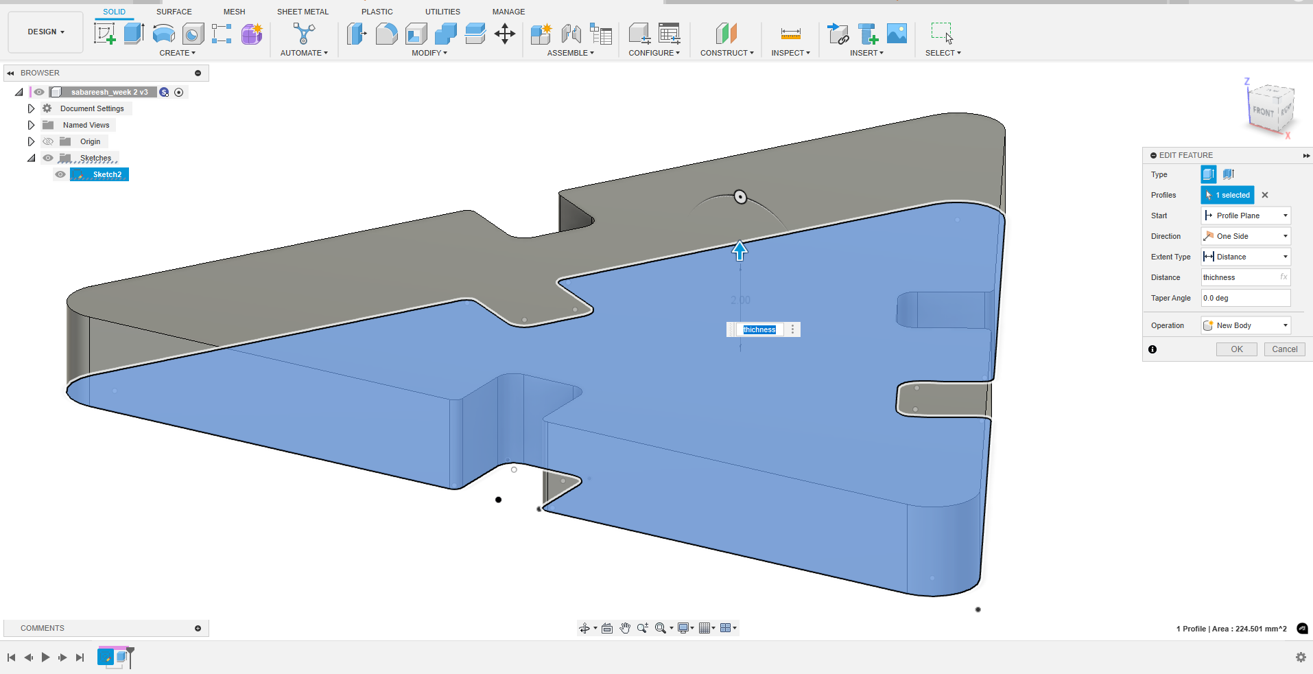
After completing the 2D sketch, I proceeded to extrude the profile to create a 3D model. Instead of entering a fixed value, I used a parametric height that I had already defined.
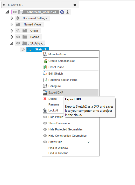
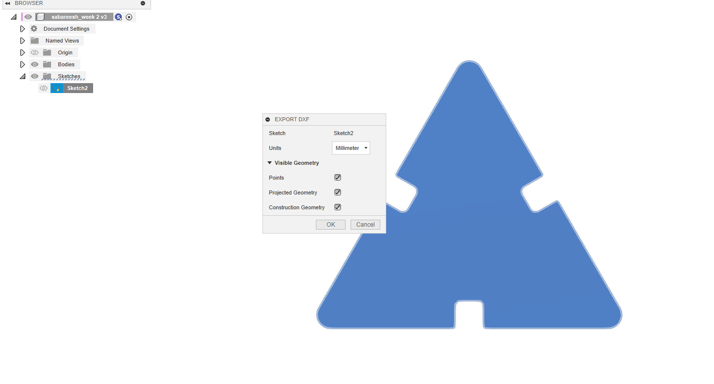
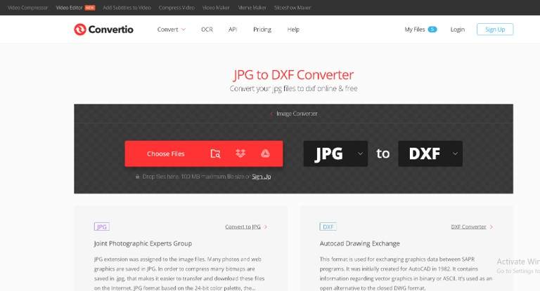
Once the parametric 2D sketch and extrusion were complete, I exported the final design as a DXF file for fabrication. Using Fusion 360’s right-click > Save as DXF option on the sketch, I ensured compatibility with laser cutting and other 2D manufacturing workflows.
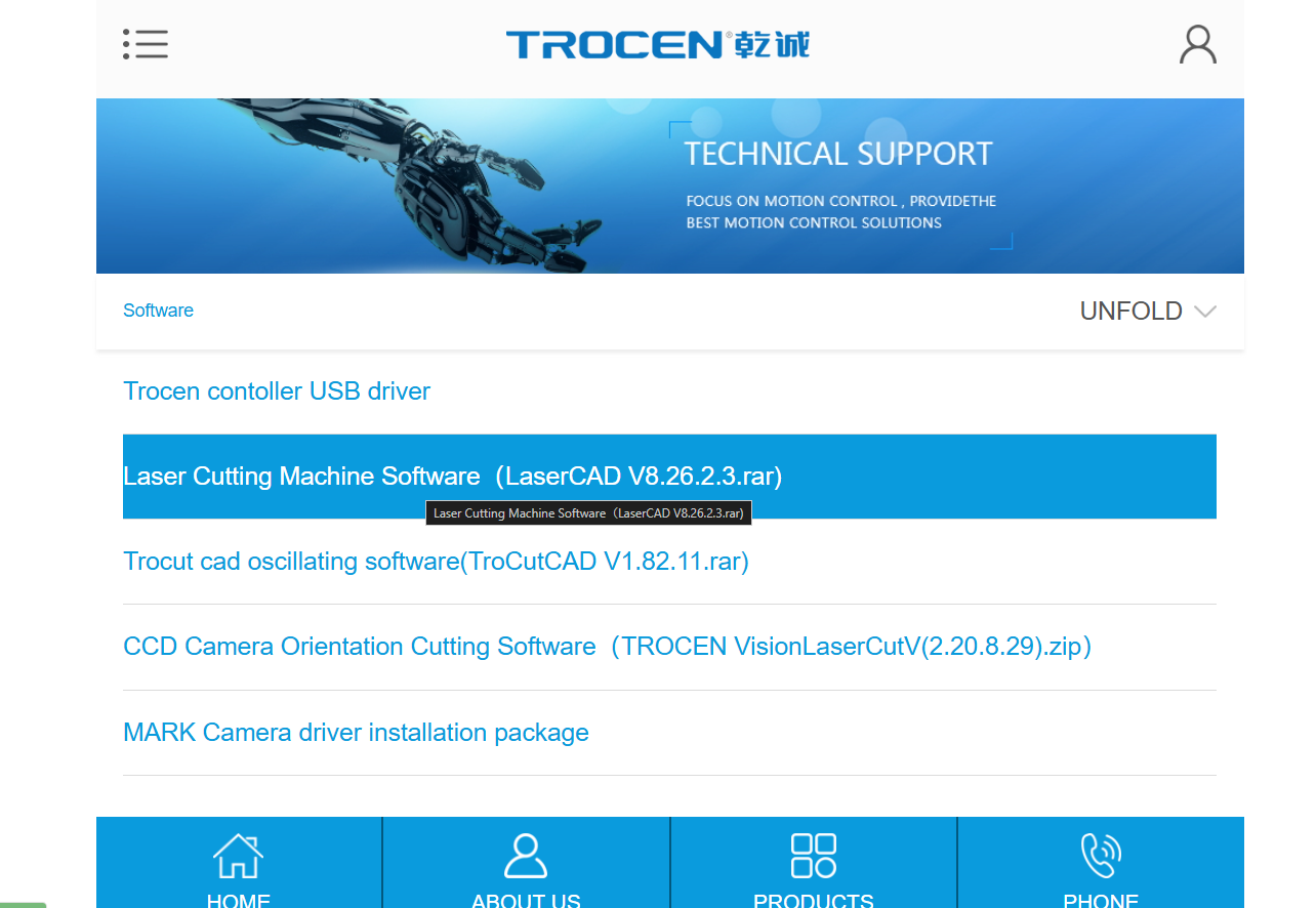
LaserCAD is a control software used for operating laser cutting and engraving machines, particularly those using Ruida or similar DSP controllers. It allows users to import vector designs (like DXF or AI files), adjust machine settings such as speed, power, and layers, and send cutting or engraving instructions directly to the laser machine. LaserCAD offers precise control over laser operations, including setting cutting order, optimizing paths, and previewing the output before cutting. It's widely used for managing workflow in laser-based fabrication.
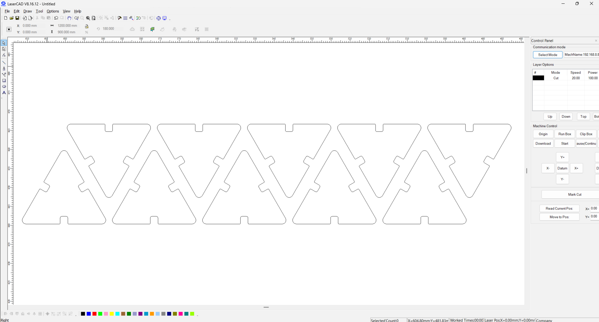
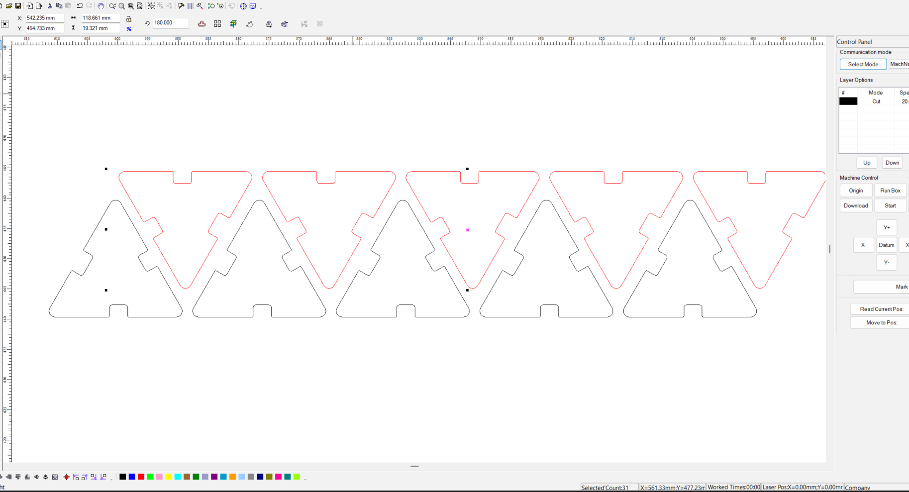
After installing LaserCAD, I imported the DXF file of my design. To optimize material usage, I created an array of the design along the X-axis using the clone tool. For better alignment and efficiency, I flipped alternate parts by 180 degrees and arranged them precisely between the gaps.
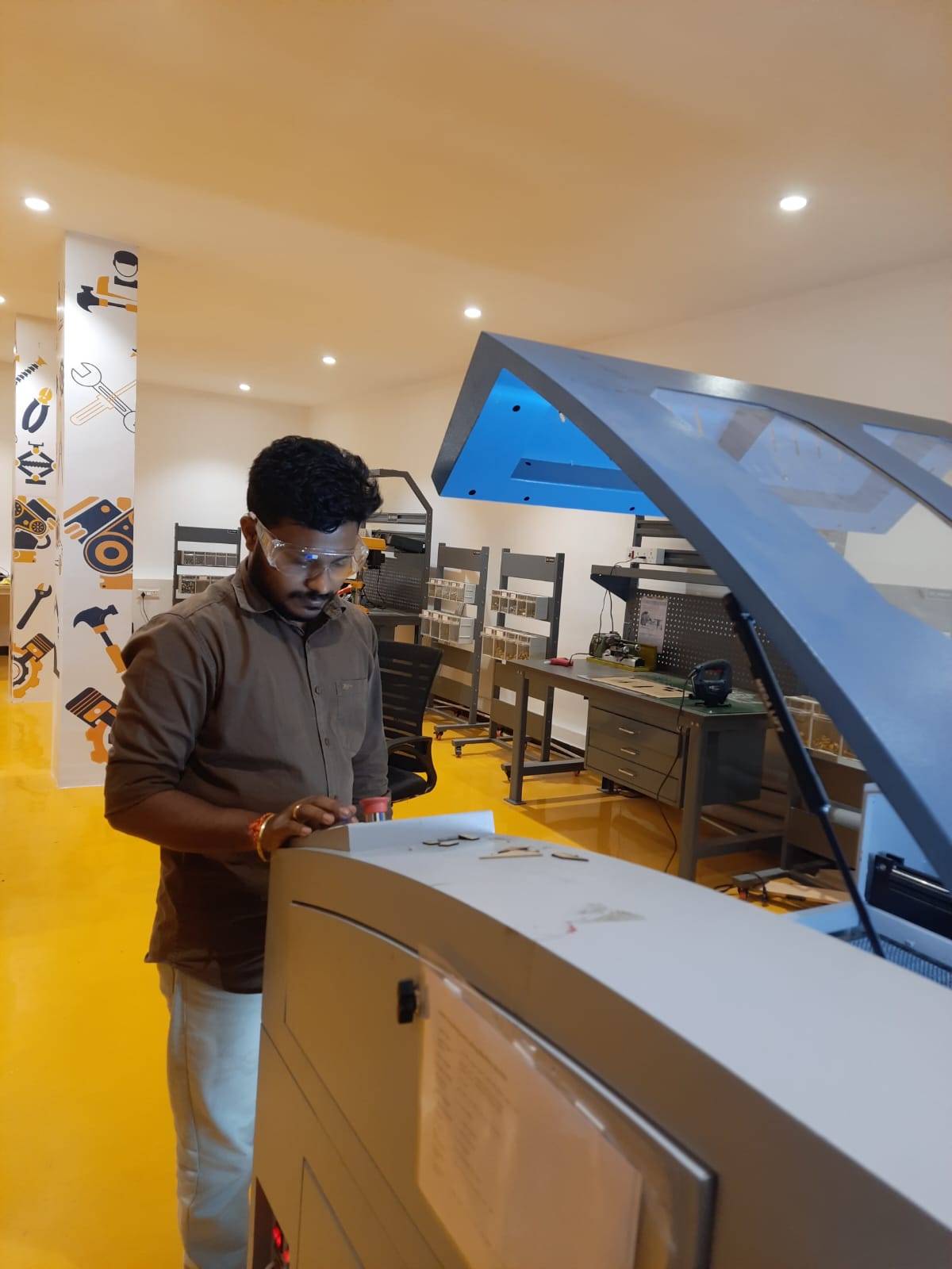
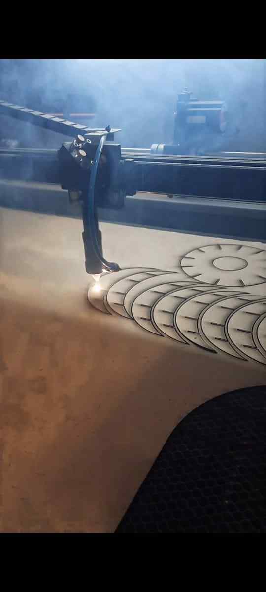
Before powering on the Laser Cutting Machine, ensure that the chiller unit is turned ON and properly functioning. The chiller helps regulate the laser tube’s temperature and prevent overheating. Wait until the chiller stabilizes around 25.4°C to 26°C, which is the optimal operating temperature for our machine. Once the temperature is within this range, it is safe to switch on the Laser Cutting Machine for efficient and safe operation.
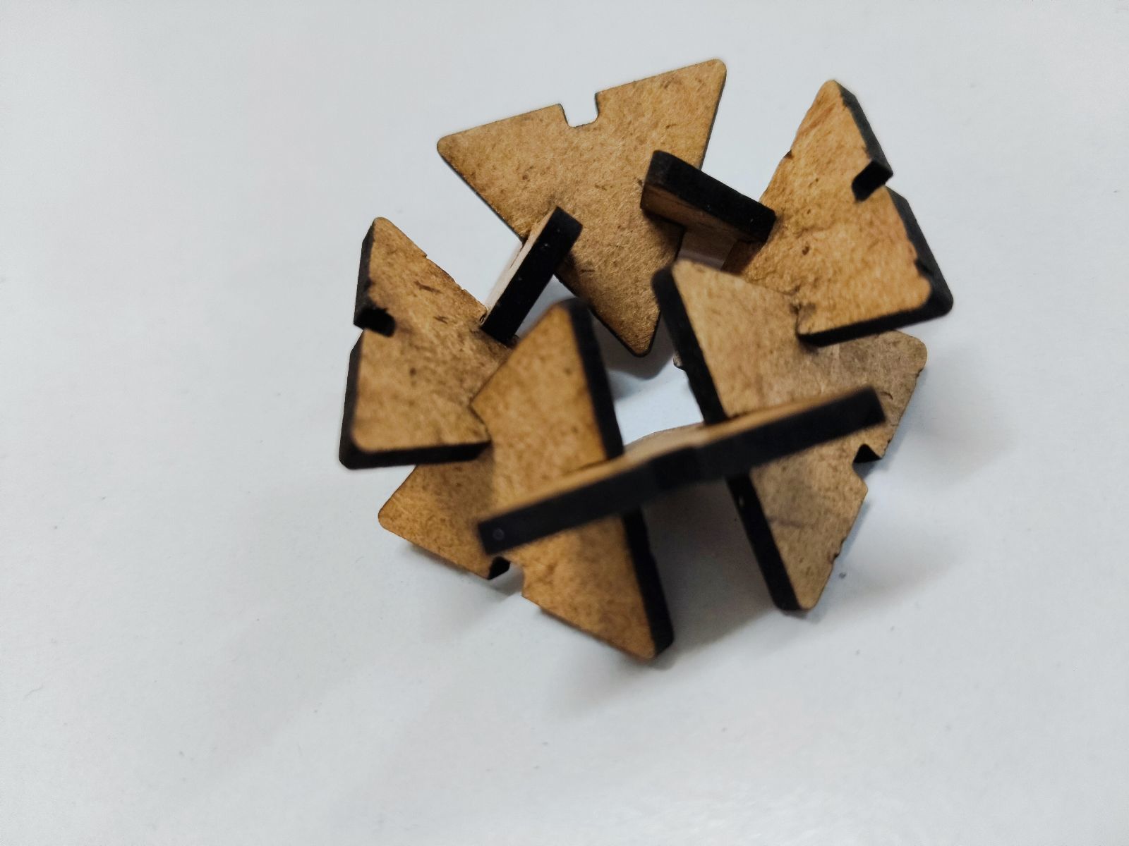
I used 2 mm thick MDF (Medium-Density Fiberboard) as the material. The design was specifically created with press-fit joints, ensuring the parts fit together securely without the need for glue or fasteners. This method is ideal for creating precise and sturdy assemblies directly from the laser-cut parts.
Laser cad File Link 3mm Acrylic
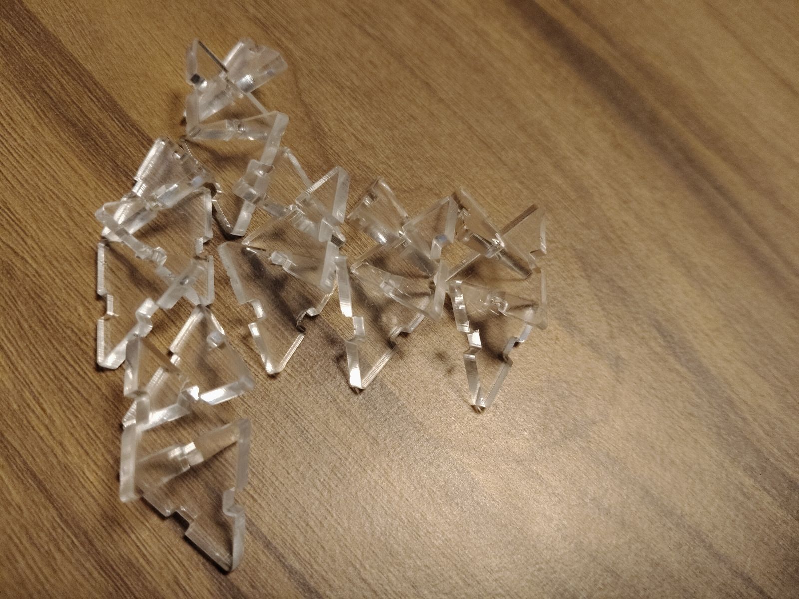
I used 3 mm thick acrylic as the material. The design was optimized for press-fit assembly, allowing the parts to snap together firmly without the use of adhesives or fasteners. Acrylic offers a clean, professional finish and is ideal for precise laser-cut constructions.
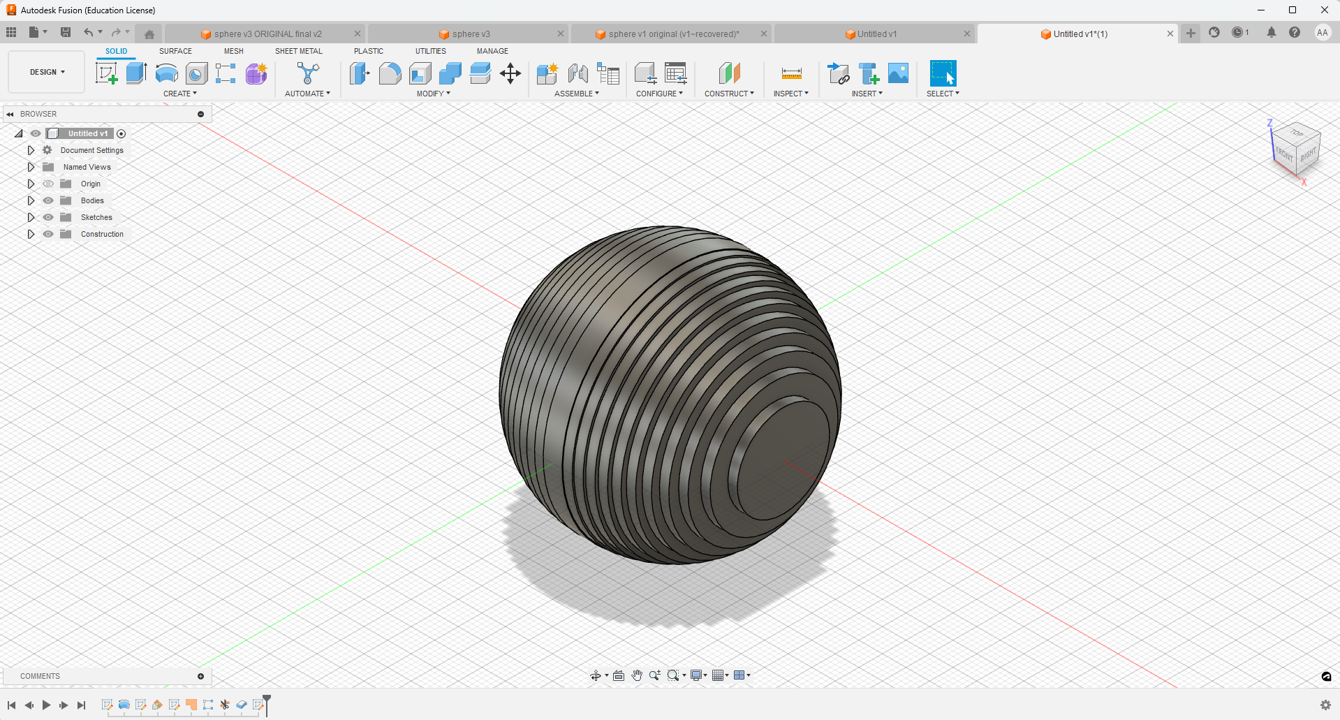
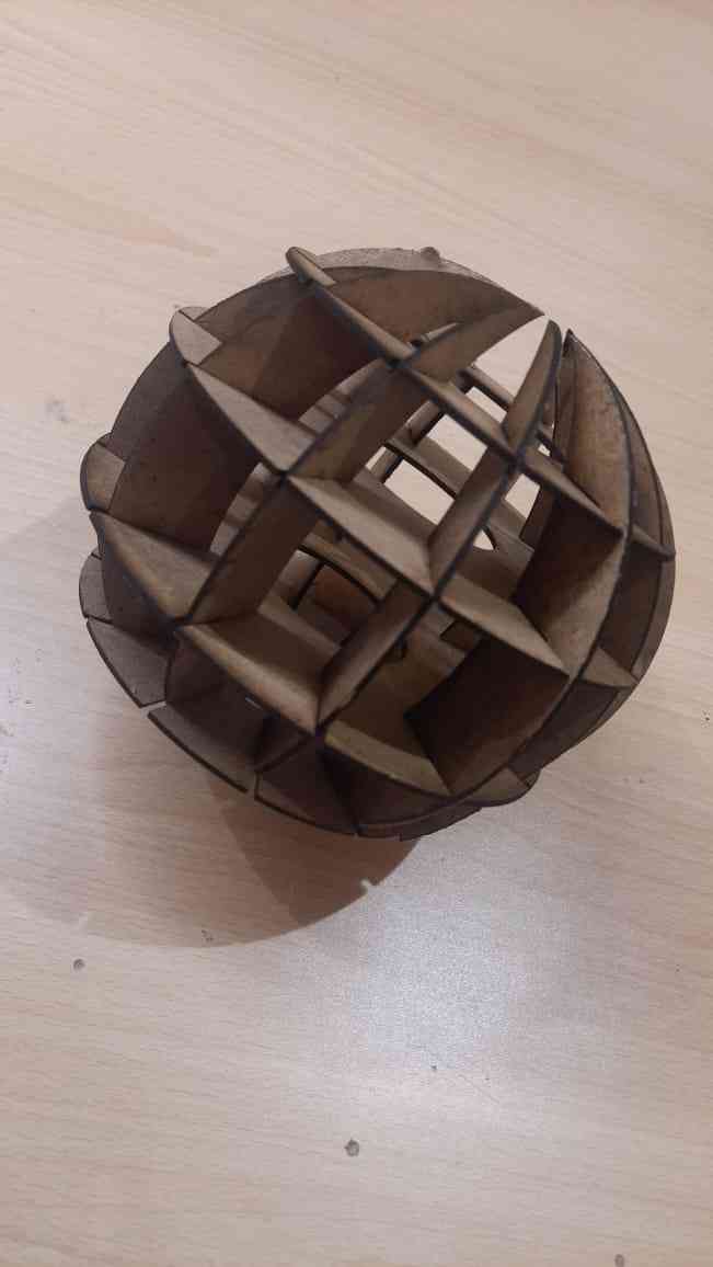
For my final project, I focused on designing the sphere in three different ways to explore various options and achieve the best fit for the outer casing. Each method considered different design criteria such as structural integrity, manufacturability, and material efficiency, ensuring versatility in the final outcome.
Design File Link
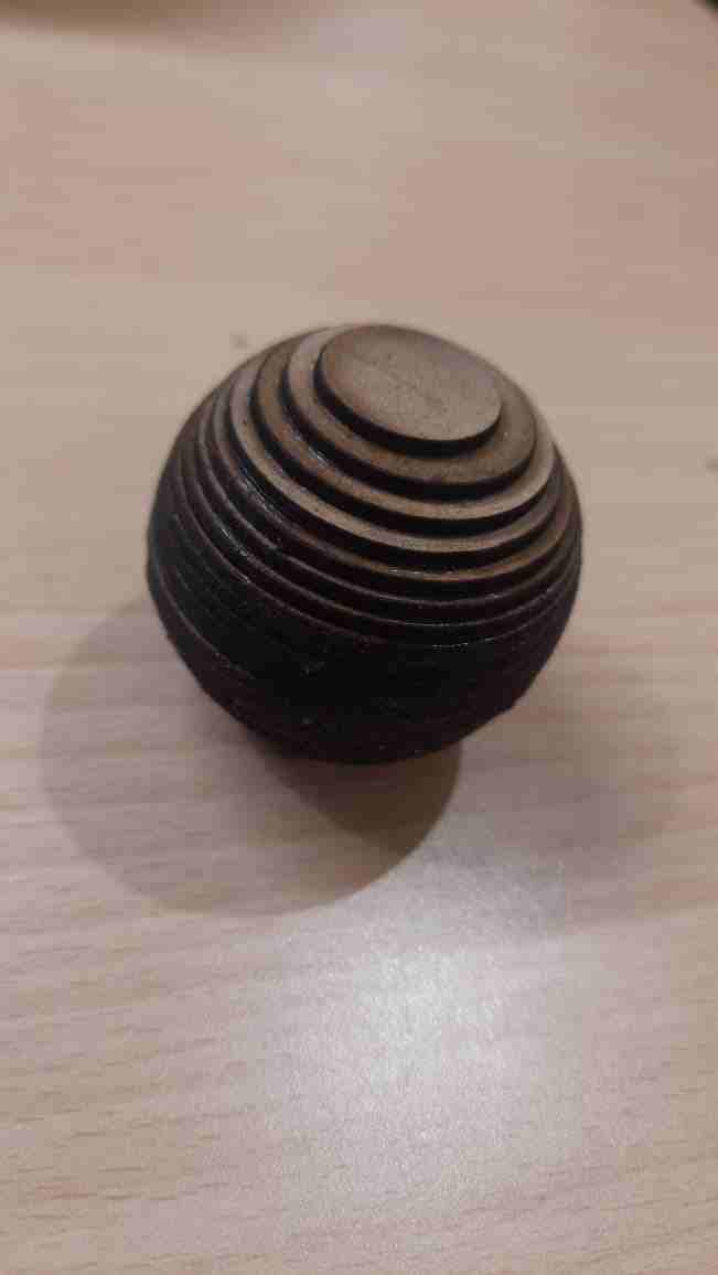
For the first approach, I used a stacking technique to design the sphere. I created a hollow sphere with two circles. The first circle was smaller, and the second one gradually increased in size by 50%. To ensure symmetry and balance, I mirrored the design, creating a smooth transition between the two layers.
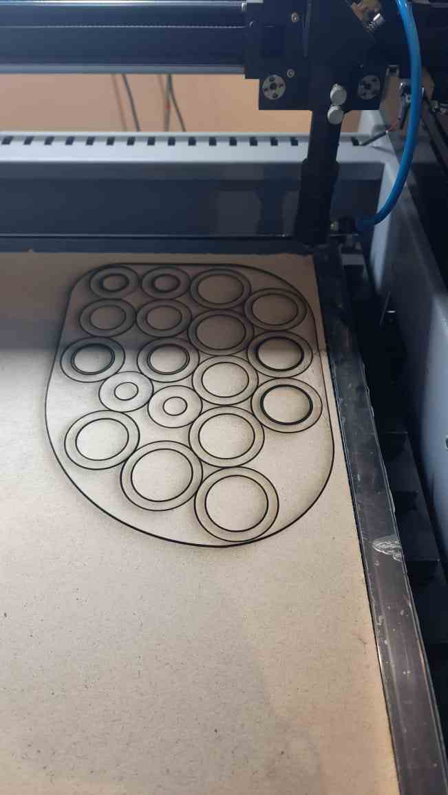
Laser cad File Link
Design File Link
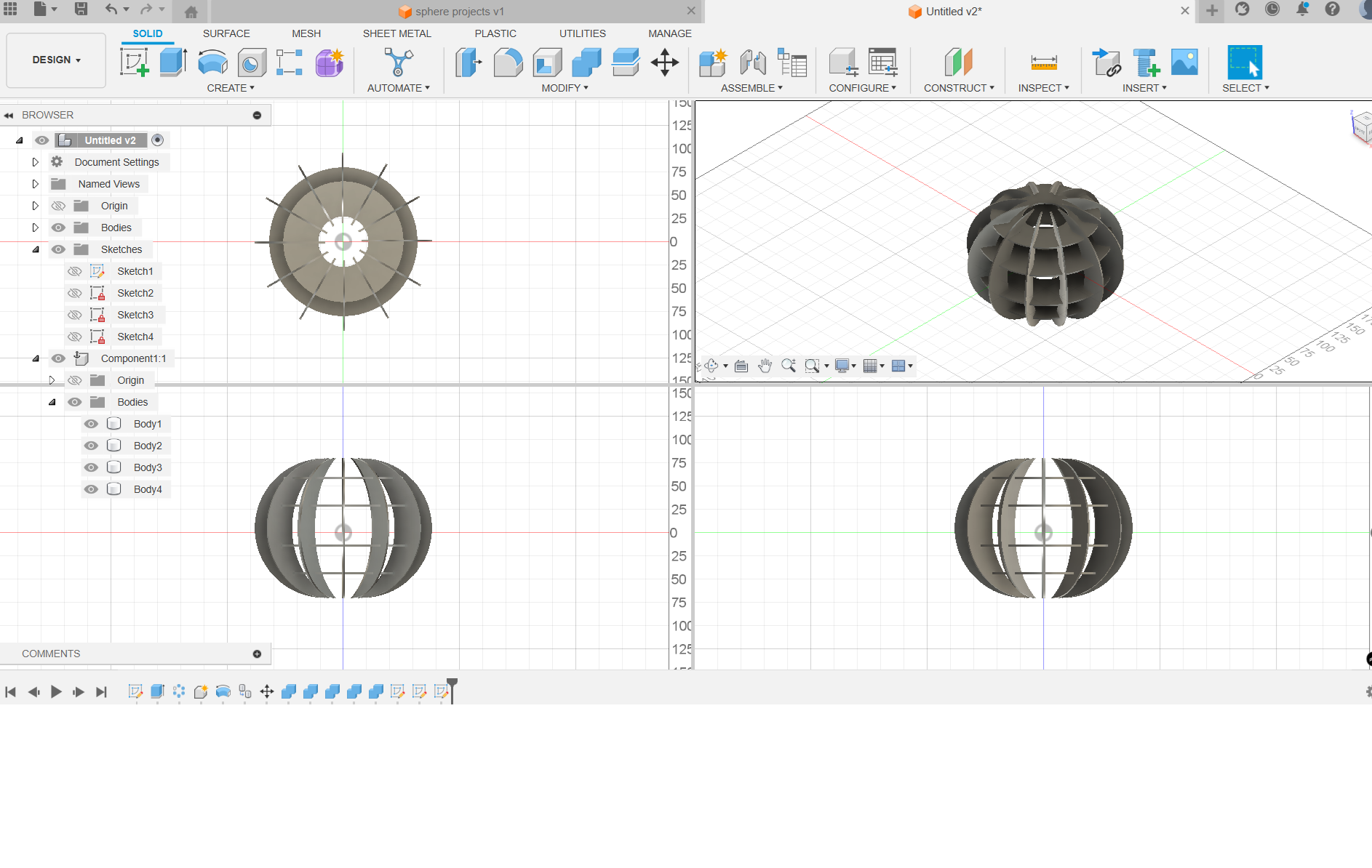
For the second method, I designed the sphere using interlocking crescent-shaped sections. This approach involved creating segments that fit together in a way that mimics the shape of a crescent moon. The interlocking design ensured a solid structure while offering flexibility for the overall assembly of the sphere.
Vinyl Cutting For the vinyl cutting process, I prepared a vector design and used a vinyl cutter to cut the shape from a sheet of adhesive vinyl. The machine followed the design precisely, cutting only the top layer. After cutting, I used transfer tape to apply the design to a surface.
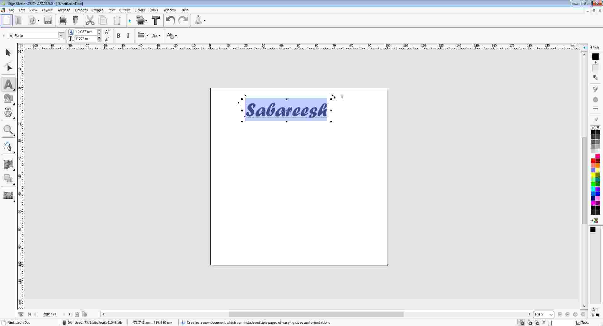
SignMaster V5 is the software used for preparing and sending designs to the vinyl cutter. It supports vector graphics, allowing precise control over cutting paths. I used SignMaster to import my design, adjust the cutting settings, and send the file to the vinyl cutter for accurate output.
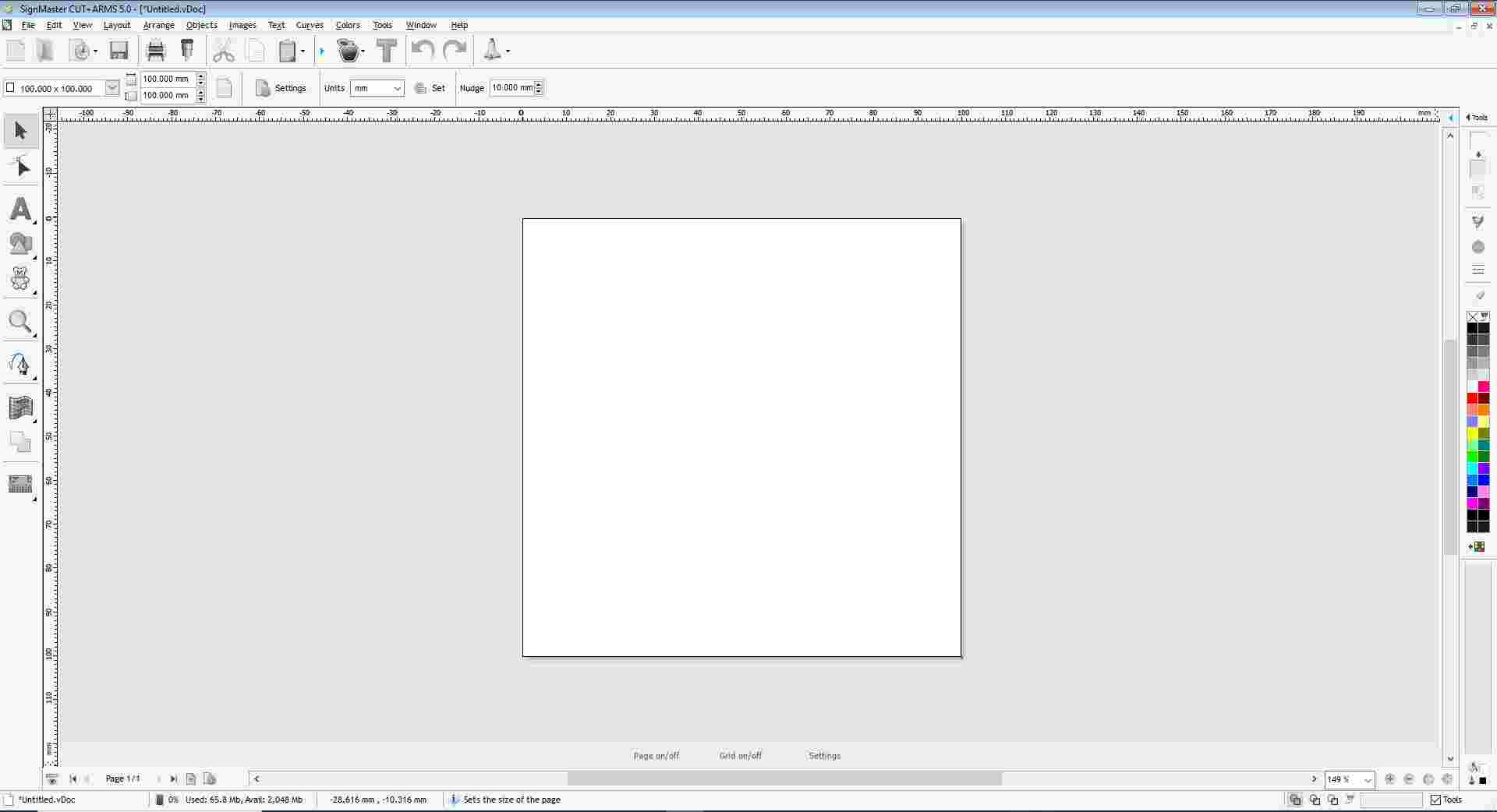
The User Interface of SignMaster V5 is clean and intuitive. It includes key features like a toolbar for drawing tools, a layer panel, and options to import or trace images. The interface allows easy manipulation of vector paths and setting parameters for cutting with precision and efficiency.
Viynal Cutting file
I used the Text Tool to enter my name into the workspace. After typing, I explored the available font styles and selected one based on my personal preference. This allowed me to customize the appearance of the text before sending it to the vinyl cutter.
Blade Intensity and Material Setup
in Vinyl Cutting
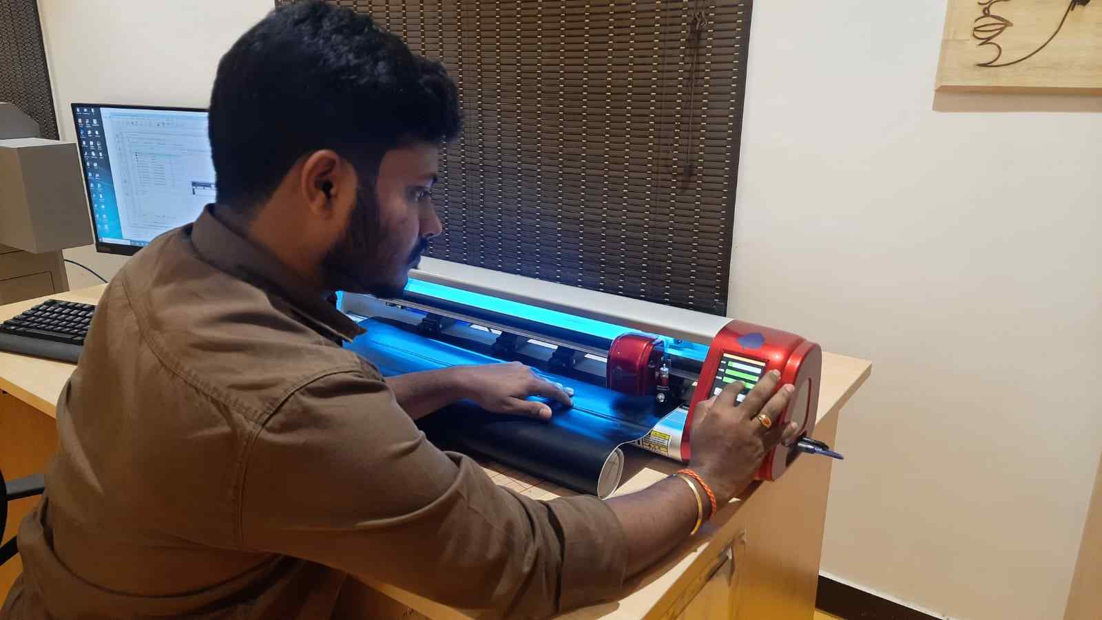
For proper vinyl cutting, I adjusted the blade intensity (or cutting force) to match the thickness of the vinyl sheet. Setting the right pressure ensured clean cuts without damaging the backing. I also carefully loaded the vinyl material into the machine, aligning it for accurate and smooth feeding.
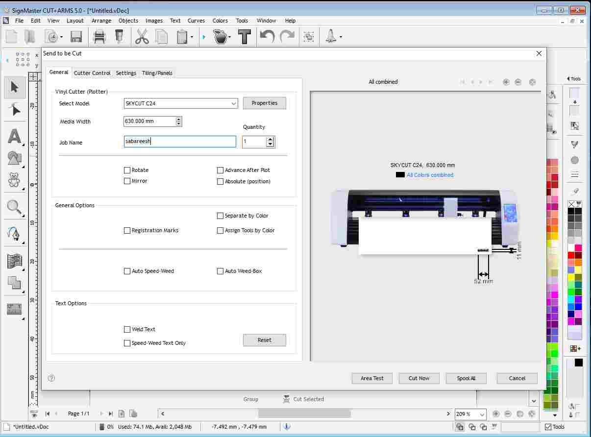
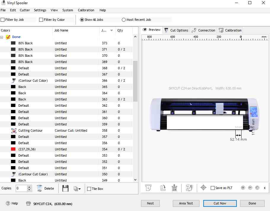
Area Test and Verification for Material Consumption
Before starting the final cut, I performed an area test run using the vinyl cutting software. This simulated the cutting path on the material to check for alignment and space usage. I verified the test on the vinyl cutter to ensure minimal material wastage and accurate placement.
After properly aligning the vinyl sheet and ensuring the design was positioned correctly, I proceeded with the cutting operation. The vinyl cutter followed the set path accurately, producing clean and precise cuts. This step was crucial to ensure the final sticker matched the intended design without misalignment.
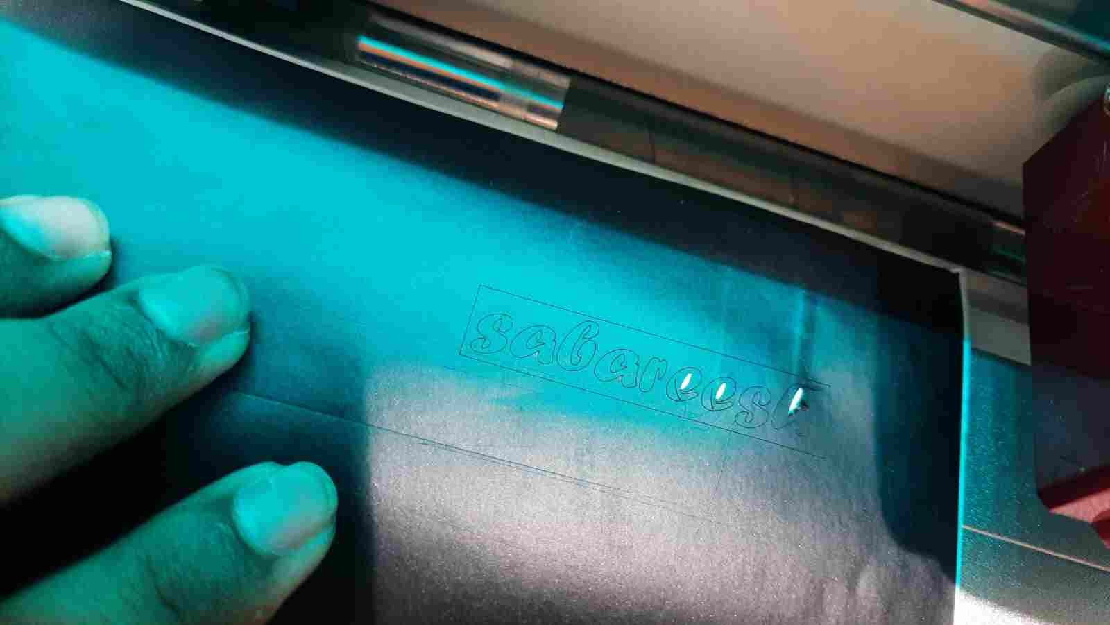
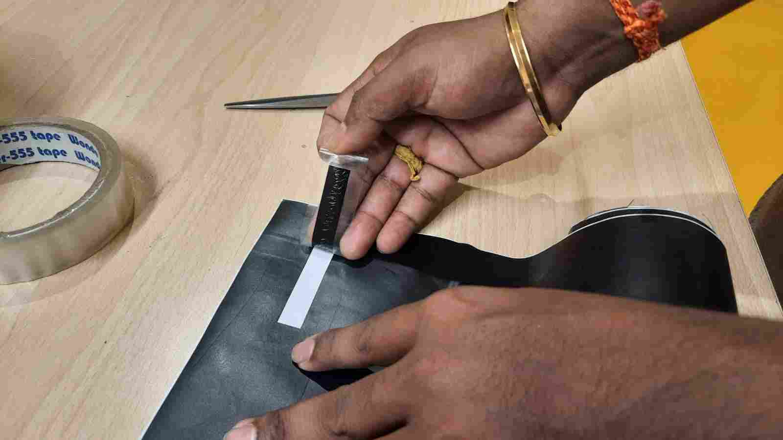
Once the cutting process was complete, I carefully removed the excess vinyl around the design, a process known as weeding. This left only the intended design on the backing sheet. The final sticker was now ready for transfer using application tape and could be applied to the desired surface.
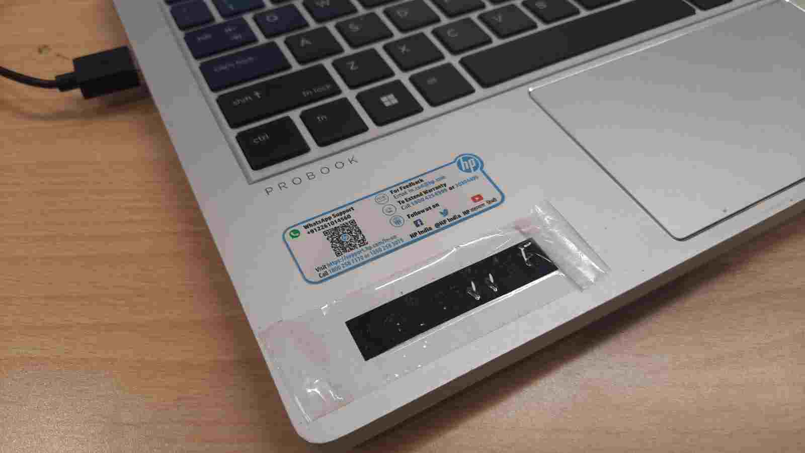
After sticking the vinyl sticker onto my laptop, I carefully separated the application tape and removed any unused or excess parts of the design. This ensured a clean and neat finish, leaving only the intended artwork firmly attached to the laptop surface without any misalignment or air bubbles.

Finally, the sticker came out perfectly, just as intended. The design was clean, well-aligned, and adhered smoothly to the laptop surface. This successful result reflected the accuracy of the cutting process, proper alignment, and careful application, making the overall vinyl cutting experience both effective and satisfying.