Group assignment
Individual assignments

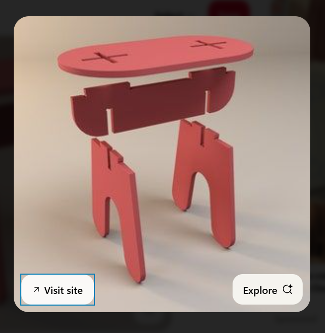
For this week, I drew inspiration from Pinterest. Browsing through various design ideas and project showcases on the platform helped me visualize creative possibilities, refine my approach, and incorporate aesthetic and functional elements into my own work. It served as a valuable reference for both design and execution.
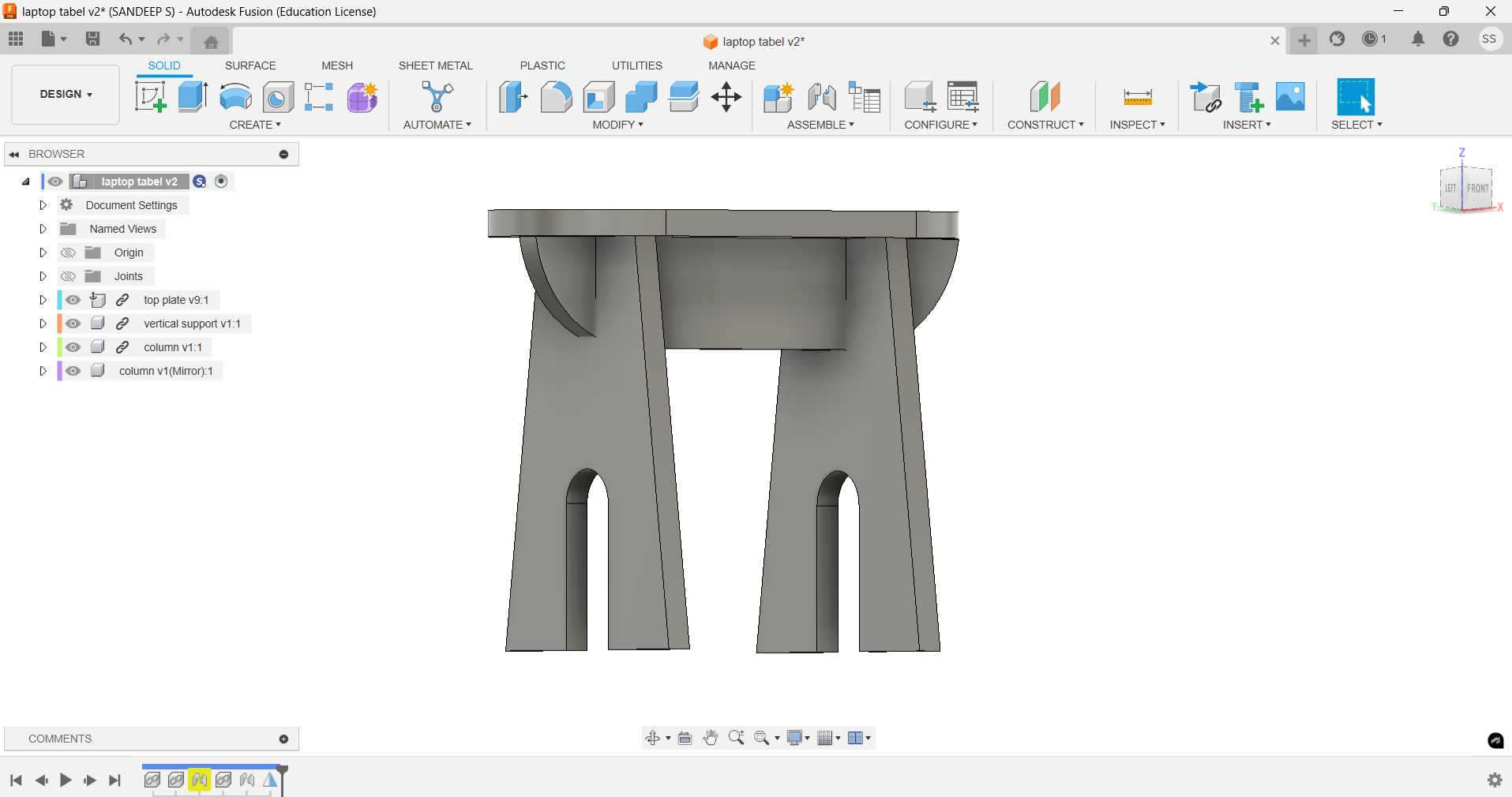
After designing and assembling the model in Fusion 360, I used the animation workspace to visualize the movement and functionality. Once satisfied, I switched to the sketch environment and exported the necessary 2D profiles as DXF files.
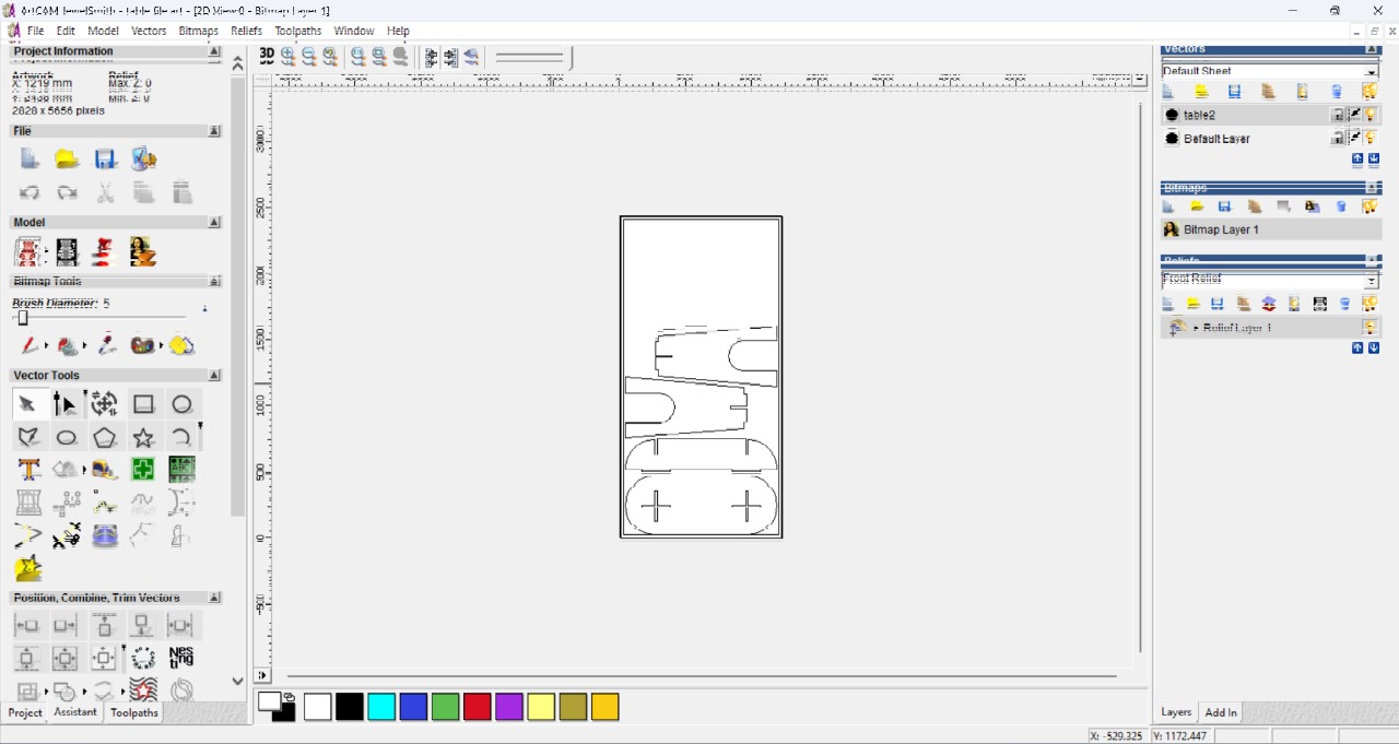
For the Computer-Controlled Cutting week, I used ArtCAM Jewelsmith 9.1, a specialized, paid software designed primarily for intricate artistic and jewelry-based designs. It offers robust tools for 2D and 3D modeling, precise vector editing, and toolpath generation. Its user-friendly interface and advanced features make it suitable for laser cutting and engraving applications.
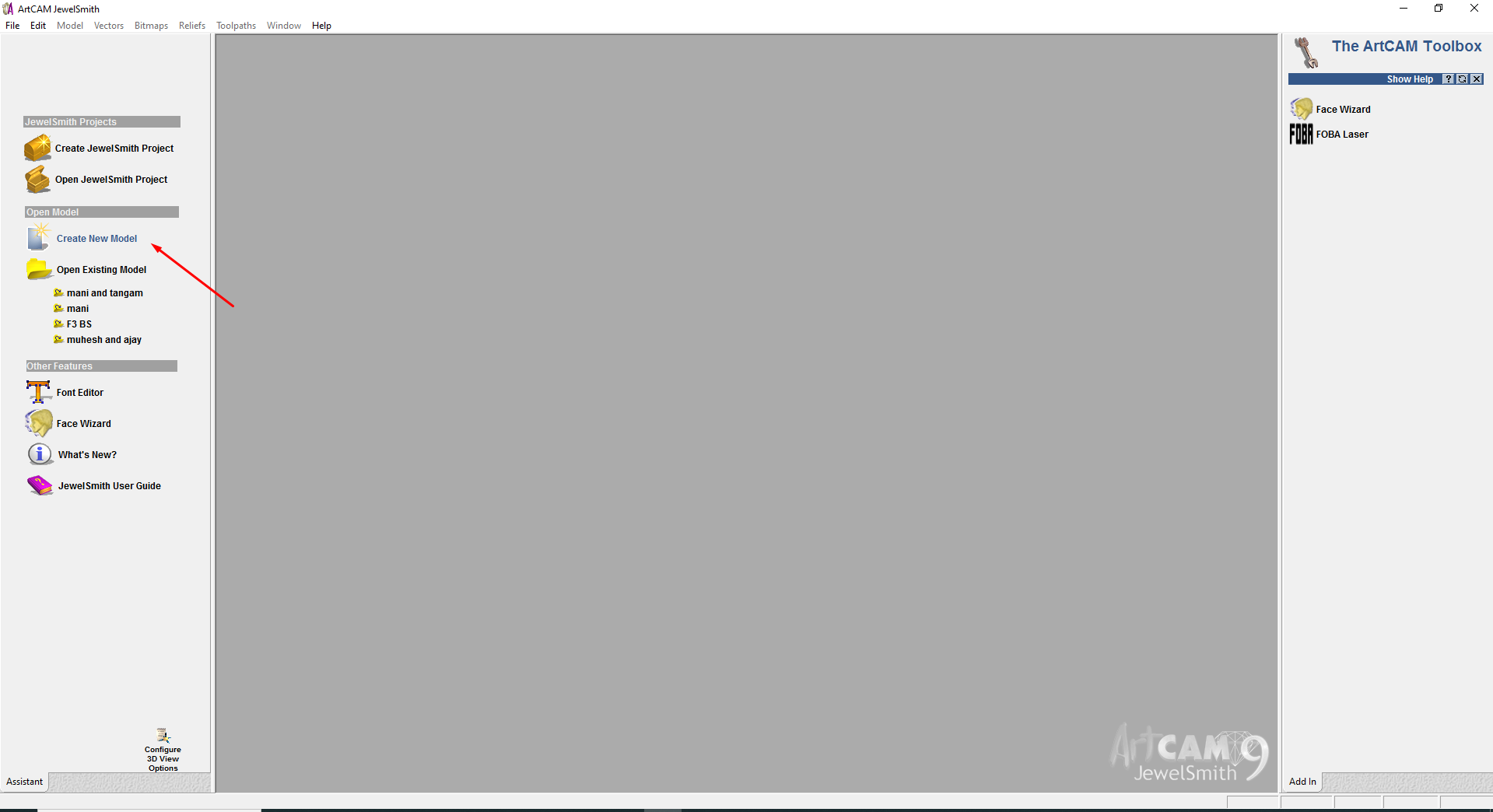
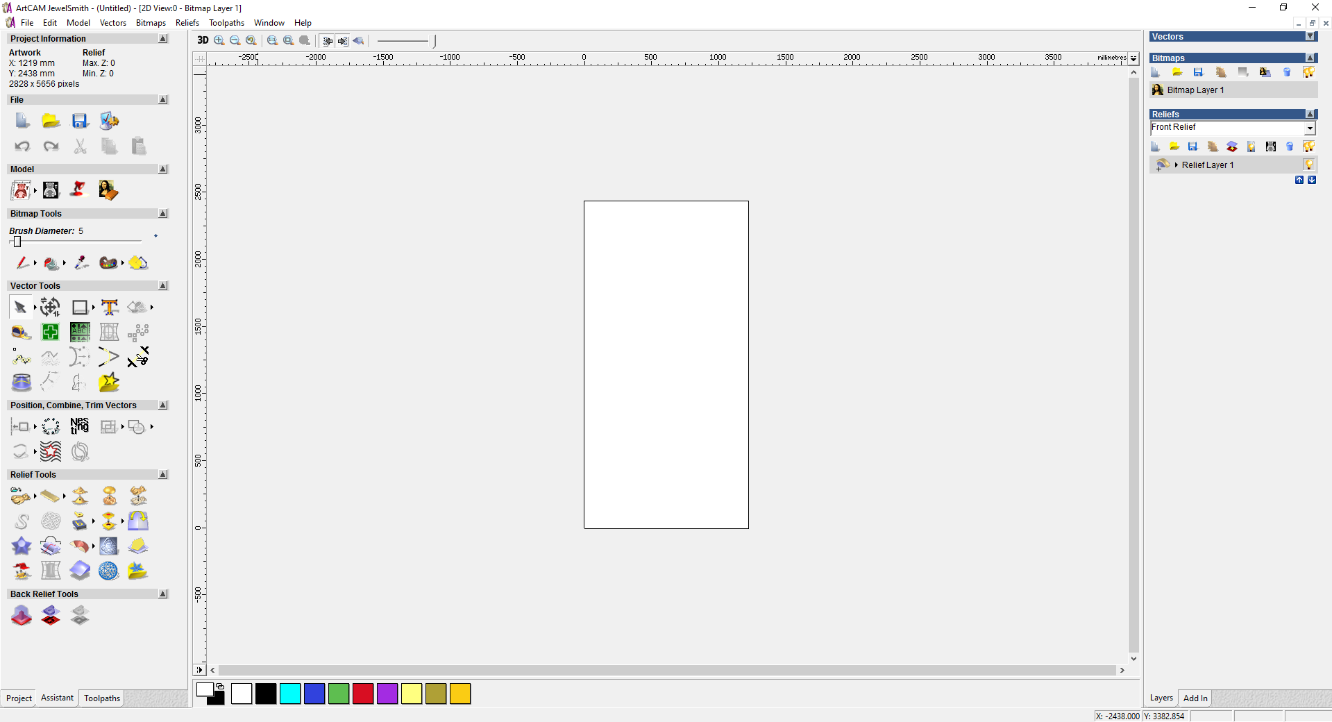
Home page of art cam jewelsmith
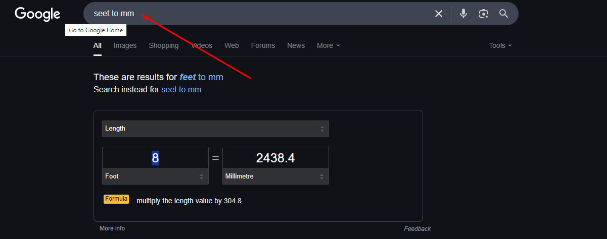
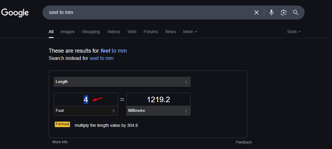
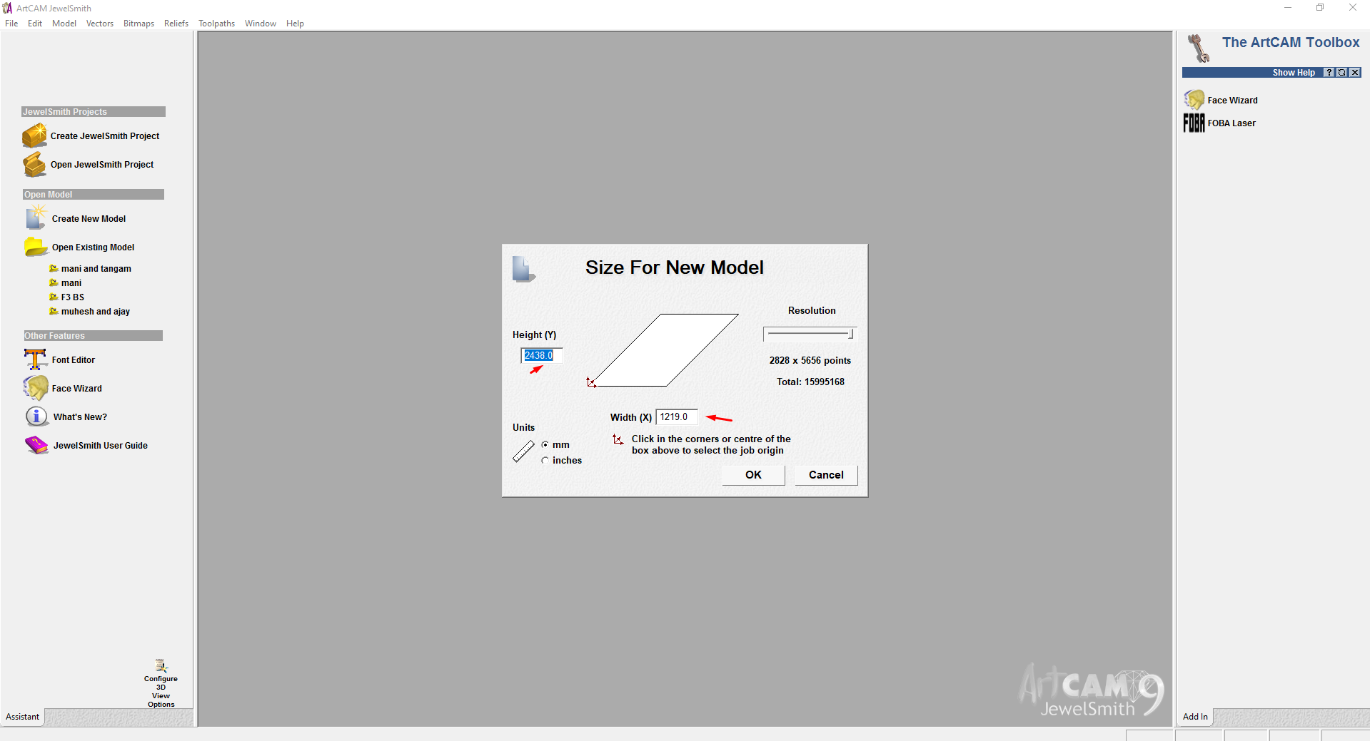
In this step, I set up the material size in millimeters (mm) for my model in ArtCAM Jewelsmith 9.1. I carefully defined the width, height, and thickness of the material to ensure the design fits accurately within the working area, enabling precise cutting and alignment during fabrication.
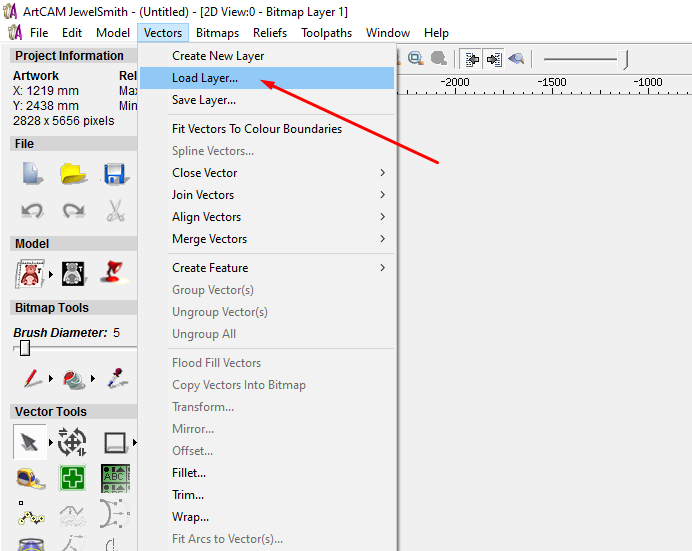
In the Vector option of ArtCAM Jewelsmith 9.1, I clicked on “Load Vector” to import my DXF file. This allowed me to bring in the design I created earlier and prepare it for toolpath creation and further operations like engraving or cutting.
I aligned it properly within the material workspace to ensure accurate machining. Proper alignment ensures the design fits within the set material boundaries and is positioned correctly for toolpath generation and cutting operations.
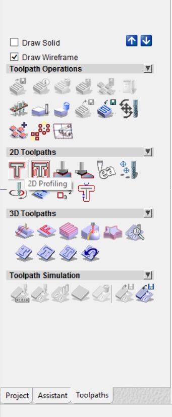
In the Toolpath settings of ArtCAM Jewelsmith 9.1, I selected the 2D Toolpath Generation option. This step is crucial for creating precise cutting paths based on the imported vector design. It allows you to define tool parameters such as depth, feed rate, and cutting strategy for accurate machining.
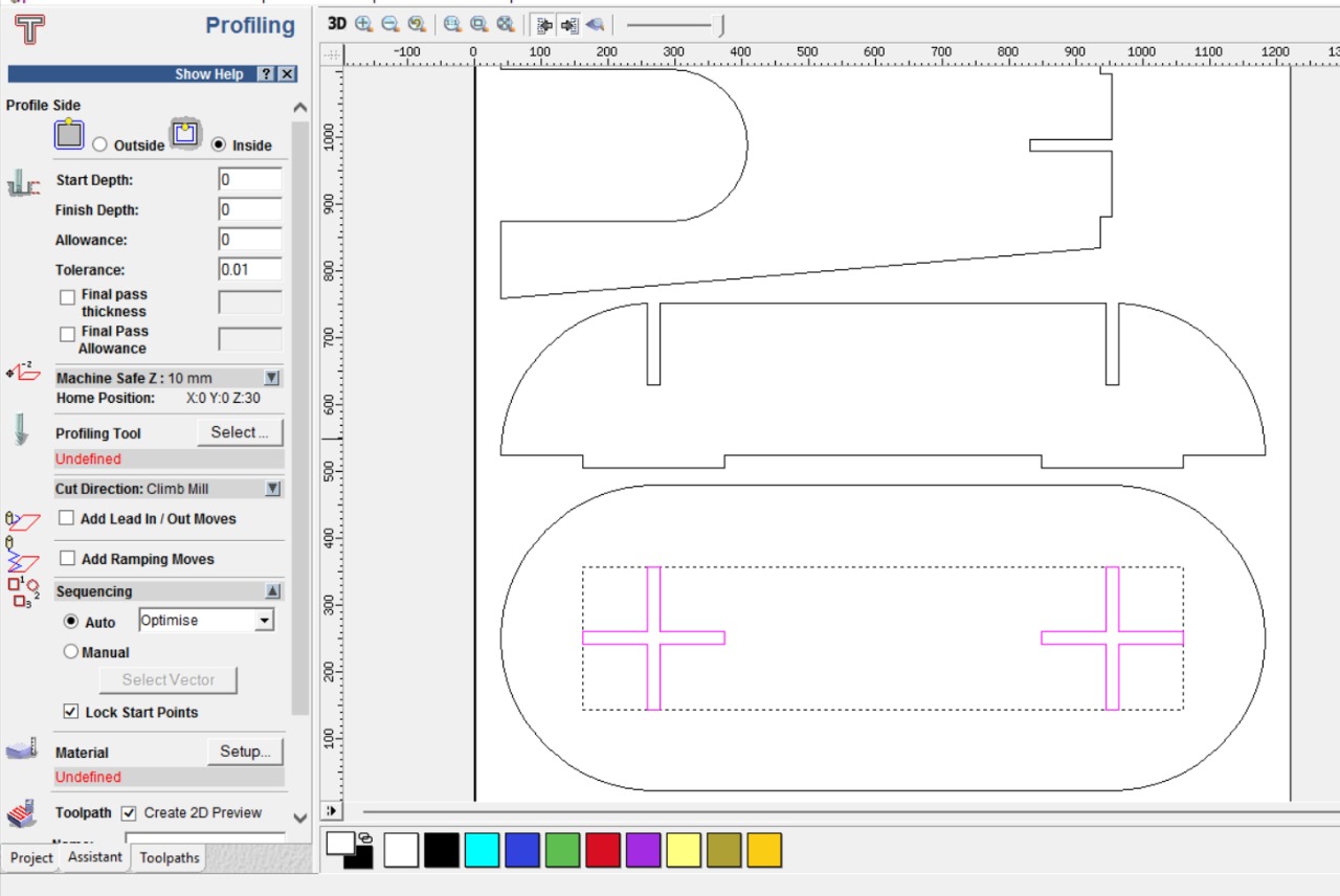
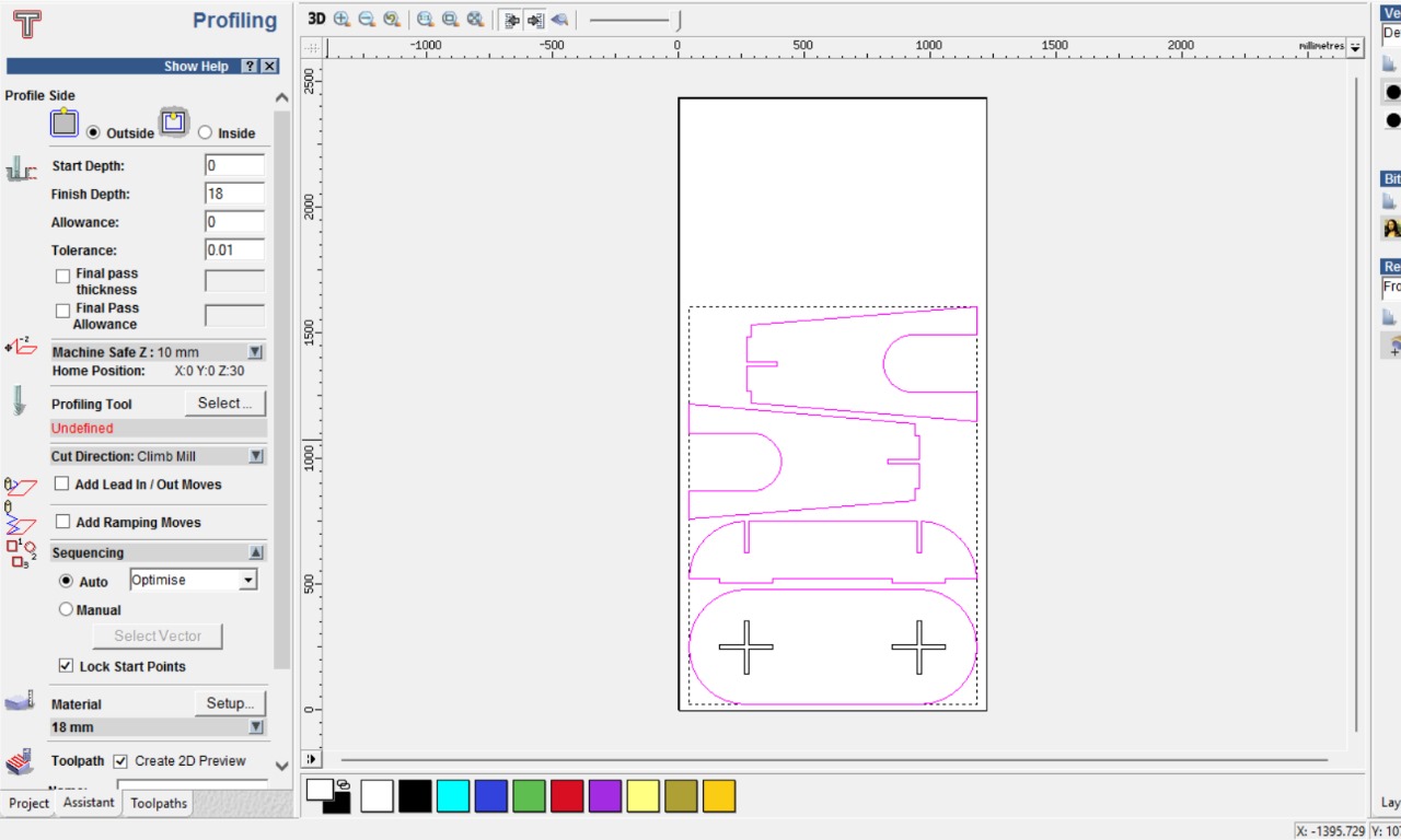
In the 2D profiling operation, the first step involves removing material from the inside of the vector shape. To achieve this, I selected the “Inside” option for the toolpath direction. Additionally, I set the cutting sequence to “Optimize” to ensure the tool follows the most efficient path during machining.
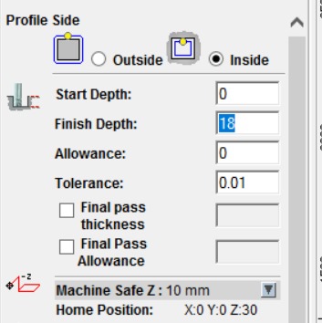
Based on the material thickness, I set the finish depth to 18 mm to ensure complete cutting through the stock. This depth setting aligns with the actual material size, allowing precise machining without leaving any excess material at the base.
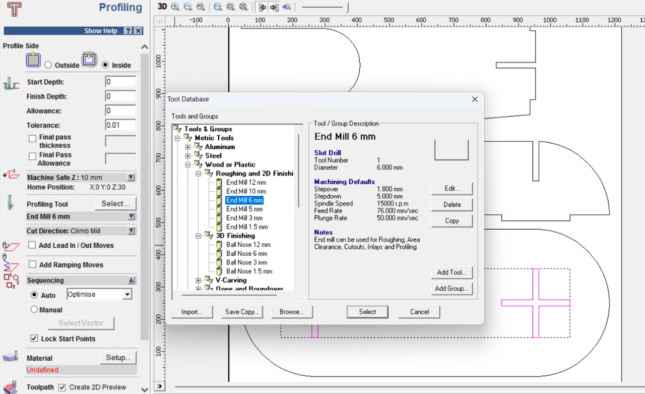
In this step, I selected the Tool Database to assign the appropriate cutting tool. I chose a 6 mm end mill, which is suitable for the 2D profiling operation. This selection defines key parameters such as spindle speed, feed rate, and cut depth for effective and accurate material removal.
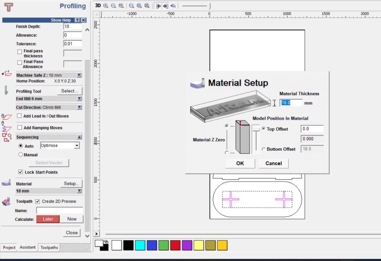
Here, I confirmed the material setup by double-checking the dimensions, origin point (X, Y, and Z zero), and thickness. This step ensures that the toolpath aligns correctly with the actual material block, preventing errors during machining and allowing precise execution of the 2D profiling process.
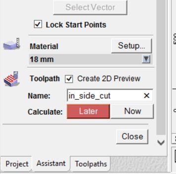
In the final step of the tool path setup, I named the operation and clicked to generate it. This process created both the geometry and the G-code needed for machining. After reviewing, I saved the tool path file for use in the CNC machine.
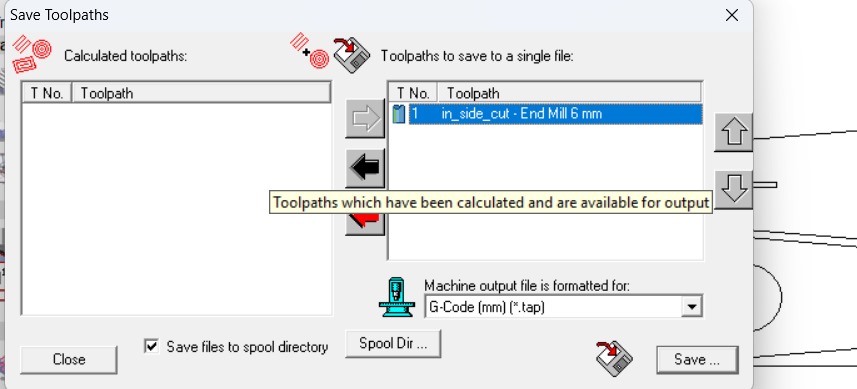
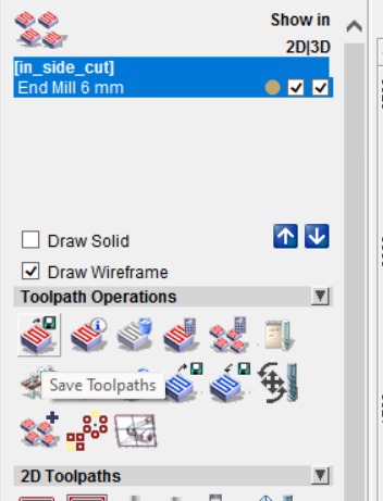
Here, I saved the generated tool path as a single TAP file format, which is compatible with the CNC machine for smooth execution of the cutting operations.
I repeated the same process for generating the outside tool path. After setting the parameters accordingly, I generated the geometry and G-code, then saved the tool path file for the outer cut, ensuring the entire machining operation is covered efficiently.
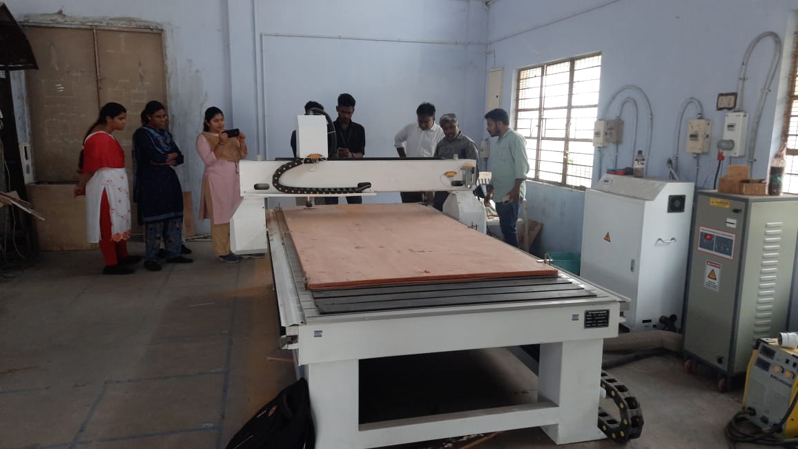
Initially, I selected 18mm plywood as the base material for the project due to its strength, durability, and ease of machining. It provides a stable foundation for precise cutting and assembly. This material choice supports the structural integrity needed for the components involved in the design and fabrication process.
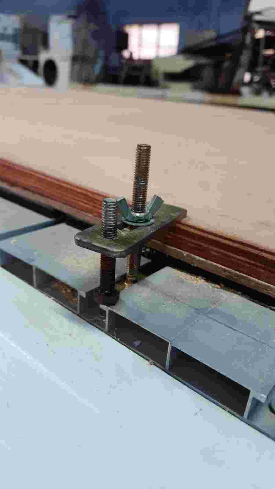
I secured the 18mm plywood using appropriate fixtures to ensure it remained stable during the machining process. This helped prevent any movement or vibration, allowing for accurate and precise cuts. Proper fixturing is essential for maintaining alignment and achieving consistent results in fabrication.
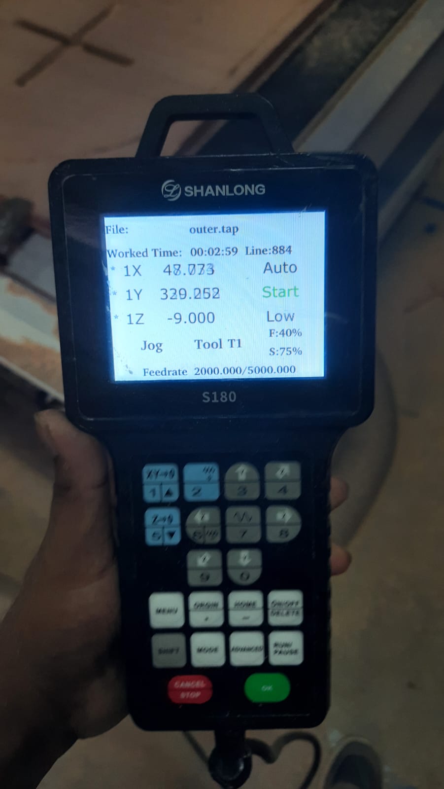
Using the teach pendant, I controlled the CNC wood routing machine to accurately set the origin point. This step ensures that the machine starts cutting from the correct reference position, allowing for precise alignment of the toolpath with the material. Proper origin setting is critical for accurate machining.
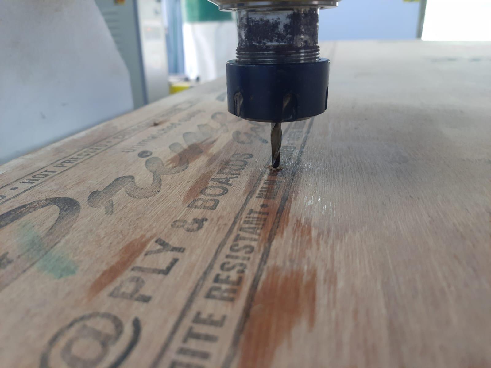
To set up the tool at the proper origin, I verified the alignment by checking the X, Y, and Z coordinates manually. I ensured the tool touched the surface accurately without damaging the material. This verification step is essential to maintain cutting precision and avoid any misalignment during machining.
After transferring the file to the CNC machine using a pen drive, I loaded the program and initiated the run. I closely monitored the initial steps to ensure proper execution, verifying that the toolpath aligned with the material setup to achieve accurate cutting results without any errors.
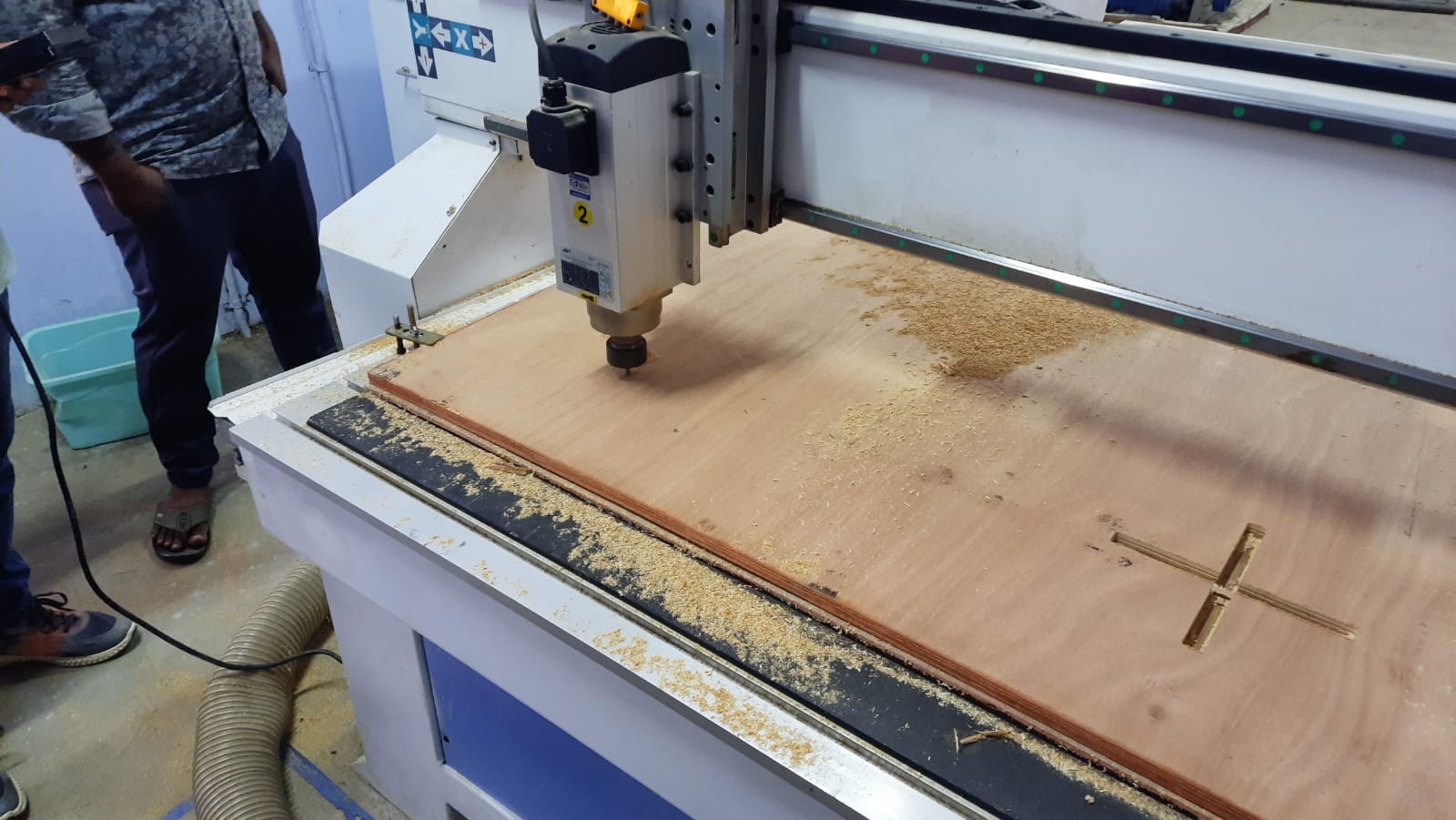
After that, I ran the code for the inside cut operation, ensuring the tool followed the correct path within the designated boundaries. I monitored the cut depth and alignment closely to maintain precision and avoid any deviation from the intended design.
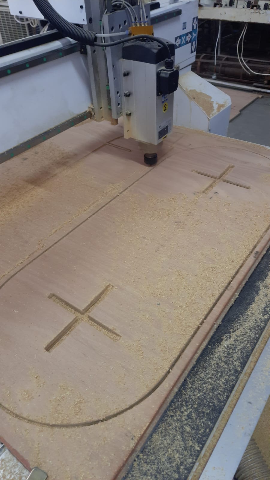
After completing the inside cut, I proceeded with the outside cut operation. This step involved cutting along the outer edges of the design to separate the final part from the material. I ensured the tool settings and origin remained accurate to achieve a clean and precise finish.
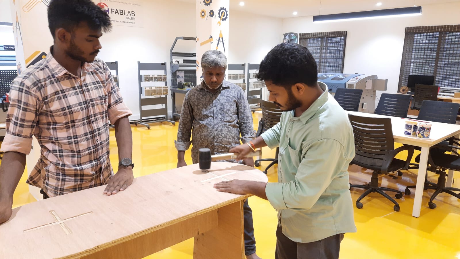
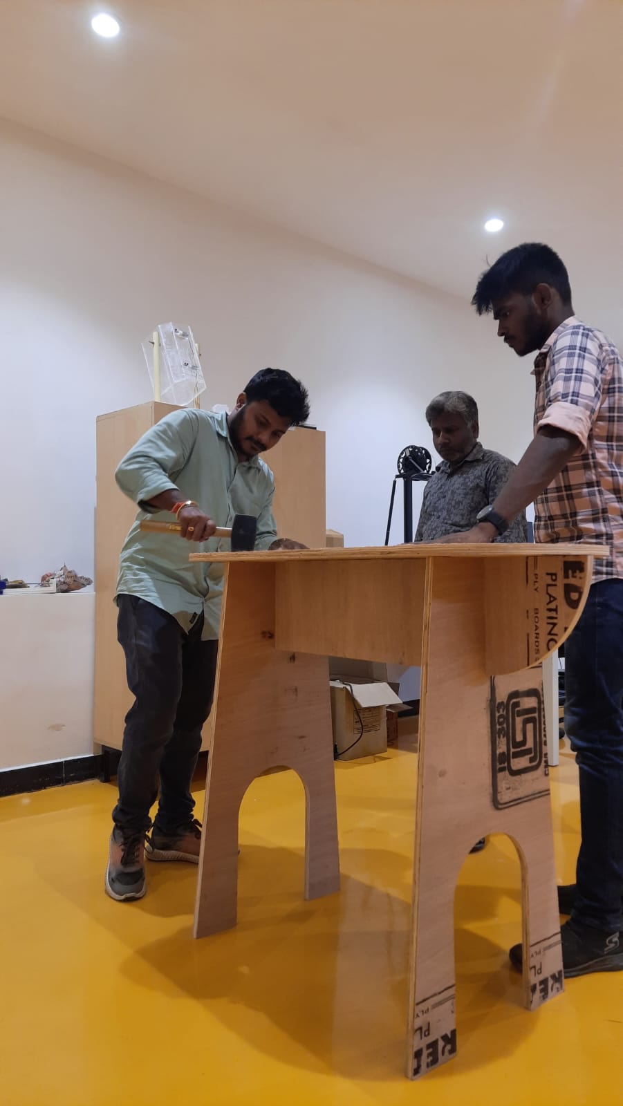
After cutting the components, I assembled them by carefully aligning and fixing each part together as per the design. I used appropriate tools and fixtures to ensure stability and accuracy during the assembly process, resulting in a structurally sound final model.
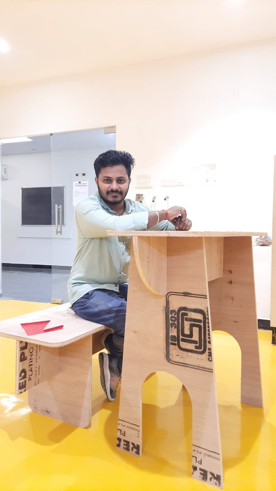
Here is the final result — this experience significantly elevated my knowledge and skills in CNC wood routing. It helped me better understand the complete workflow, from material preparation to tool setup, file transfer, cutting operations, and final assembly.