Group assignment
Individual assignments

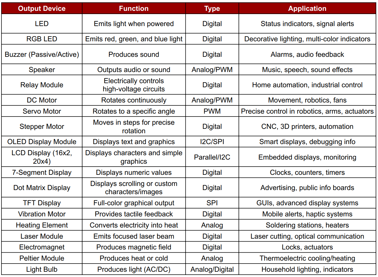
Output devices are components or peripherals used to communicate the result of processed data from a microcontroller or microprocessor to the user or other systems. These devices convert electrical signals into human-perceivable or system-recognizable formats such as sound, light, motion, or display.
I arrived at this data with the help of ChatGPT, which guided me in organizing and understanding various input devices used in electronics. It assisted in structuring the information clearly and concisely in tabular form.
In this project, I used an Arduino Nano along with the MPU6050 sensor to detect motion and orientation. The data from the MPU6050 was processed to interpret tilt or movement, and the output was visually represented using seven LEDs. Each LED indicated a specific range or direction of motion, allowing real-time feedback of sensor activity in a simple and effective way.
In this task, I used an Arduino Uno R3 with an LED, buzzer, and the Xcluma TTP226 8-Channel Digital Capacitive Touch Sensor. Each of the 8 touchpads was assigned to a section: when a pad was touched, the LED blinked once and the buzzer beeped once, providing immediate visual and audio feedback for interactive user input.
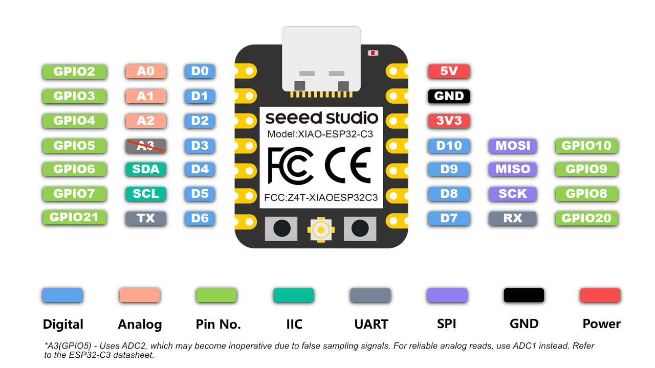
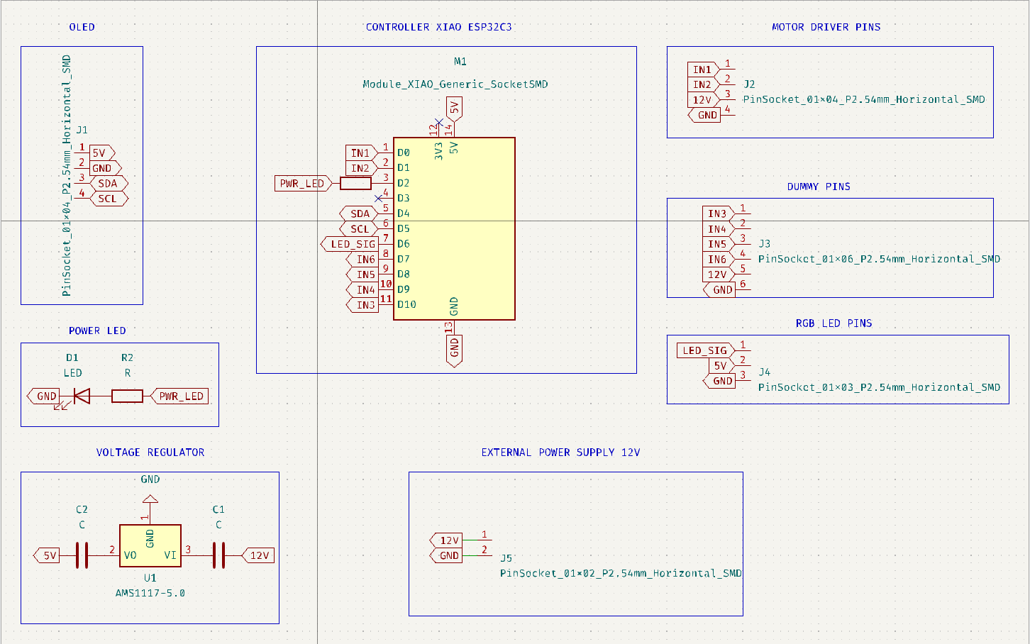
For output week, I used the ESP32-C3 module as the microcontroller due to its compact size, low power consumption, and integrated Wi-Fi and Bluetooth. It supports various communication protocols like PWM, I2C, and SPI, making it ideal for controlling output devices such as LEDs, buzzers, displays, and motors efficiently.
Summary of ESP32-C3 Datasheet
The ESP32-C3 is a cost-effective, low-power, 32-bit RISC-V microcontroller with integrated Wi-Fi and Bluetooth LE 5.0. Designed for secure and efficient IoT applications, it provides robust wireless connectivity and flexible I/O configuration.
Technical Specifications
Microcontroller: 32-bit RISC-V Single-Core CPU
Clock Speed: Up to 160 MHz
SRAM: 400 KB
ROM: 384 KB
Flash: External (typically 4 MB via SPI)
EEPROM: Not available (can be emulated using flash)
Operating Voltage: 3.0V to 3.6V
Input Voltage (recommended): Via 3.3V regulated supply
Wi-Fi: IEEE 802.11 b/g/n (2.4 GHz, up to 150 Mbps)
Bluetooth: Bluetooth 5.0 LE with Mesh and Long Range
Digital I/O Pins: 22 GPIOs
ADC: 12-bit, up to 6 channels
UART: 2
SPI: 2
I2C: 1
PWM: Available on all GPIOs
Timers: Multiple hardware timers
USB: USB 2.0 Full-Speed (native support)
Security: AES, SHA, RSA, ECC, Flash Encryption, Secure Boot
Power Consumption: Active Mode ~130 mA, Light Sleep ~0.8 mA, Deep Sleep ~5 µA
Package: QFN32 (5 mm × 5 mm)
Supported Tools: ESP-IDF, Arduino IDE, PlatformIO, MicroPython
ESP32-C3 Pin Details
The ESP32-C3 supports flexible pin assignment using its GPIO matrix, allowing peripherals to be remapped to available pins as needed.
Digital I/O Pins (GPIO0 to GPIO21)
All GPIOs are multifunctional and support input, output, pull-up/down, PWM, and peripheral mapping. Maximum current draw per GPIO is approximately 20–40 mA depending on usage.
Important GPIOs
GPIO0 – Used for boot mode selection during flashing
GPIO1 and GPIO3 – Default UART TX and RX (avoid using when Serial Monitor is active)
GPIO9 and GPIO10 – Usually connected to internal flash, should not be used for I/O
GPIO19 and GPIO20 – USB D- and D+ on some modules
Analog Input Pins (ADC1 Channels)
ESP32-C3 has 6 ADC1 channels with 12-bit resolution, mapped to GPIOs like GPIO0 to GPIO5. These are used for reading analog voltages from 0 to 3.3V.
Power Pins
3V3 – Regulated 3.3V power input
GND – Ground reference
EN – Chip enable (reset if pulled low)
VBUS – USB power input (5V on USB)
LDO Cap – Capacitor pin for internal LDO regulator (used in specific modules)
Communication Pins
Serial (UART):
Default UART uses GPIO1 (TX) and GPIO3 (RX). UARTs can be remapped to other pins using software.
SPI:
SPI0 is reserved for internal flash. SPI1 is available for general-purpose communication and can be mapped to any free GPIOs.
I2C:
Supports one I2C controller in master/slave mode. SDA and SCL lines can be assigned to most GPIOs. Common assignments are GPIO4 (SDA) and GPIO5 (SCL).
USB:
Native USB 2.0 interface supported on modules like ESP32-C3-DevKit. D+ and D- are usually mapped to GPIO19 and GPIO20.
Security Features
Hardware-based Flash Encryption
Secure Boot (version 2)
Cryptographic acceleration for AES-128/256, SHA-2, RSA-3072, and ECC
Digital Signature Peripheral
Summary
Digital Pins (GPIO0–GPIO21): General-purpose I/O with PWM and peripheral mapping
Analog Pins: 6 channels of 12-bit ADC
Power Pins: 3.3V input, multiple GND, EN, USB VBUS
Communication Interfaces: UART, SPI, I2C, USB
Connectivity: Integrated Wi-Fi (2.4 GHz) and Bluetooth 5.0 LE
Security: Supports advanced encryption, secure boot, and digital signature
Power Modes: Active (~130 mA), Light Sleep (~0.8 mA), Deep Sleep (~5 µA)
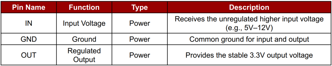
The IC REG LINEAR 3.3V 1A SOT-223 is a linear voltage regulator that provides a stable 3.3V output from a higher input voltage (typically 5V to 12V). It can supply up to 1 ampere (1A) of current, making it suitable for powering microcontrollers, sensors, and other low-power devices. Packaged in the compact SOT-223 surface-mount form, it is ideal for PCB designs where space-saving is essential. This regulator ensures smooth and noise-free voltage, which is crucial for sensitive electronics.
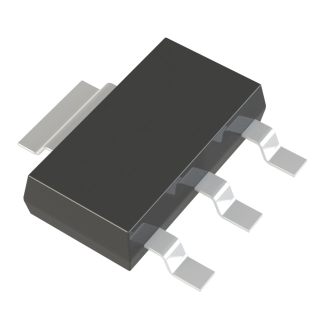
IC REG LINEAR 3.3V 1A SOT-223 - Data sheet
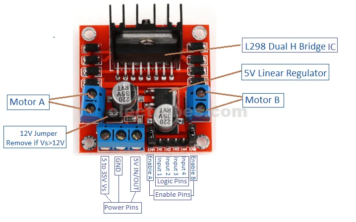
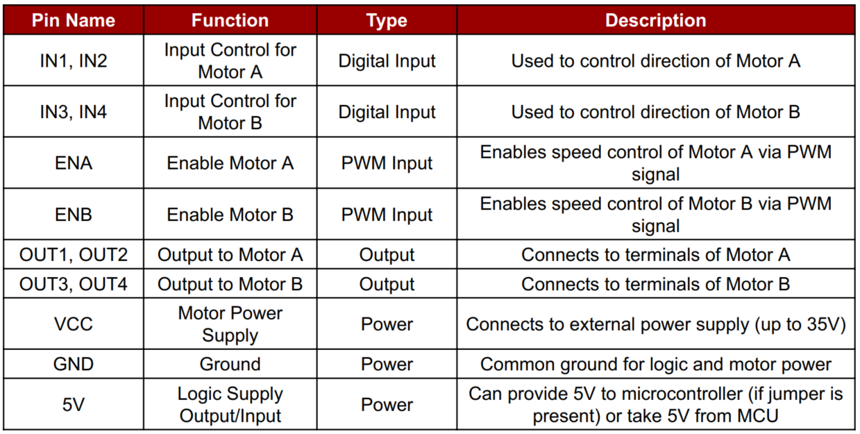
L298N Dual H-Bridge Motor Driver Data Sheet
The L298N is a popular dual H-Bridge motor driver IC that allows you to control the speed and direction of two DC motors independently. It can also be used to control a stepper motor. Operating up to 46V and 2A per channel, it is ideal for use in robotics, automation, and DIY projects involving motorized movement. The module features built-in heatsinks, easy screw terminals, and PWM support, making it user-friendly for beginners and professionals alike.
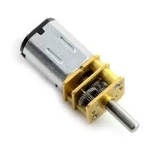
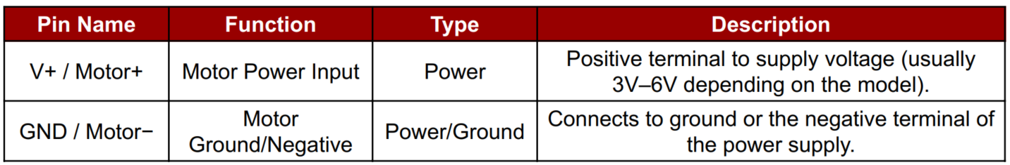
N20 Metal Gear Motor Data Sheet
The N20 Motor 3V 300 RPM is a miniature DC gear motor known for its balance of speed and torque. Operating at 3V, it delivers 300 RPM, making it suitable for lightweight robotics, DIY electronics, and precision control mechanisms where compact size and moderate power are essential.
In this video, I learned about the N20 motor, a compact DC gear motor ideal for robotics. It operates efficiently at 3V with 300 RPM, providing sufficient torque for small mechanisms. The video covered its working principle, wiring, applications, and how to control it using a motor driver.
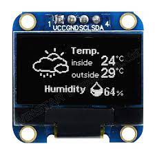
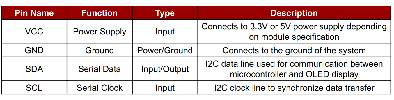
OLED Display Module Blue color data sheet
An OLED (Organic Light Emitting Diode) Display Module is a self-emissive display that uses organic compounds to emit light when current flows through them. These displays are popular in embedded systems and electronics projects due to their lightweight, low power consumption, and high contrast visibility, even in dark environments.
Adafruit SSD1306 Library - GitHub
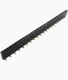
Female header pins are connectors used to make reliable and detachable connections between electronic components or modules. They consist of a row of sockets that accept male pins, allowing easy interfacing between boards, sensors, or microcontrollers. In my project, I used female header pins to connect sensors and modules to the ESP32-C3 microcontroller without soldering them directly. This helps in easy testing, replacement, and modular design.
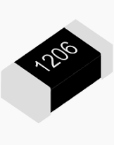
A resistor is a passive electronic component that limits or regulates the flow of electric current in a circuit. It provides resistance, measured in ohms (Ω), and helps control voltage and current to other components. In my project, resistors were used to protect components like LEDs and ensure stable operation.
Basic Power Formulas
Power (P) = Voltage (V) × Current (I)
2× N20 Motors
Voltage:
3V
Current (each): ~160 mA
Power (each): 3V × 0.16A = 0.48W
Total for 2 motors: 0.48W × 2 = 0.96W
OLED Display 0.96"
Voltage: 3.3V or 5V (depending on model)
Typical Current: ~20–30 mA
Power: 3.3V × 0.03A = ~0.1W
Motors (2): 0.96W
OLED: 0.1W
ESP32-C3: ~0.16W (typical, 3.3V × 50mA)
Total: ~1.2W
Open Arduino IDE → Select "ESP32C3 Dev Module" under Tools > Board
Install these libraries from Library Manager: Adafruit SSD1306 and Adafruit GFX
Define motor driver pins (e.g., IN1, IN2, IN3, IN4) for L298N.
I2C OLED typically uses SDA and SCL (check your ESP32-C3 pinout).
Initialize:
Serial.begin(115200), Motor pins as OUTPUT, OLED with display.begin()
Show welcome/status message on OLED.
Loop Function (loop()) : Use Serial.available() to check for user input.
Update both motor states and OLED message accordingly.
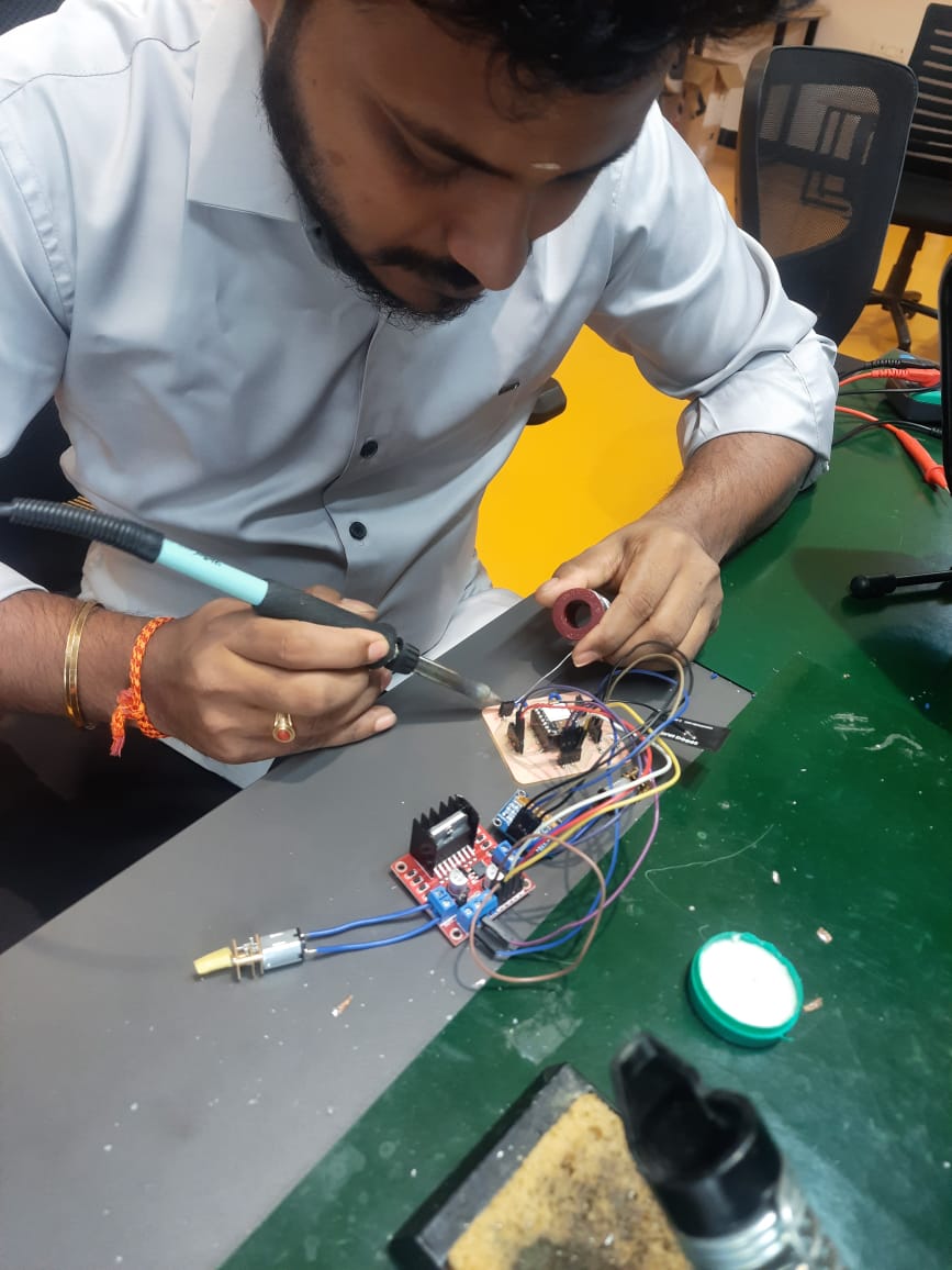
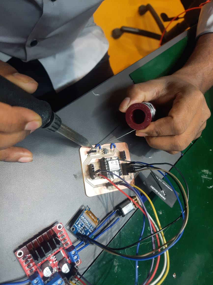
Initial Attempt with Female Header Pins
I began soldering female header pins for the power supply. Though the connection was made, it didn’t feel strong or properly secured.
Desoldering to Fix the Issue
I tried to desolder and resolder the pin for a better joint. During this process, a problem occurred.
Copper Pad Damage
While desoldering, the copper pad lifted from the PCB. This usually happens when excessive heat is applied or when pressure is used while pulling the component.
Learning: Maintain Proper Soldering Temperature
Use a soldering iron with a temperature setting around 300°C to 350°C (572°F to 662°F). Higher temperatures can easily damage the copper layer.
Learning: Solder Correctly the First Time
Apply solder slowly and steadily on the first try. Avoid rushing or applying too much pressure to ensure a reliable and safe joint without needing rework.
For the Output Devices week, I controlled two N20 motors (3V, 200 RPM) using the Serial Monitor. When I sent '1', the motors rotated forward for 3 seconds. Sending '2' made them rotate backward for the same duration. This setup demonstrated basic directional motor control through serial commands.
Let’s see this in action during the final project, where these motors will be part of a special bot. The bot will integrate motor control with sensors and wireless communication, showcasing how individual components like the N20 motor contribute to the full functionality of the final robotic system.