Group assignment
Individual assignments

Embedded programming (EP) involves writing software that directly interacts with hardware in resource-constrained environments. It is used to control devices like sensors, motors, displays, and communication modules through microcontrollers or embedded processors. Programs, often written in C or C++, must be optimized for speed, memory usage, and power efficiency due to limited hardware capabilities. Embedded systems frequently operate in real-time, requiring fast and reliable responses to external events. Developers use debugging tools like serial monitors and JTAG/SWD interfaces to test and troubleshoot firmware, which is the permanent software stored in flash memory. Communication with other devices is often achieved through protocols like I2C, SPI, UART, or wireless methods such as Bluetooth and Wi-Fi. EP is essential in various domains including IoT, robotics, automotive systems, industrial automation, and consumer electronics, with power management being a crucial consideration, especially for battery-powered applications.
What is embedded programming
You Need to Know About Embedded System Programming link
How it works
Program Development: Code is written using languages like C/C++ in an Integrated Development Environment (IDE) such as Arduino IDE, Keil, or MPLAB
Compilation & Linking: The source code is compiled into machine code (binary) that the microcontroller can understand.
Uploading to Hardware: The compiled program is uploaded to the embedded system's memory (usually via USB, Serial, or SWD interface).
Execution: Once powered, the microcontroller fetches, decodes, and executes the instructions continuously.
Interfacing with Hardware: The code controls inputs (like sensors) and outputs (like LEDs or motors) in real-time.
Monitoring & Debugging: Developers use debugging tools, serial monitors, and LEDs to check the functionality and fix issues.
Summary of Arduino Uno R3 Datasheet :
The Arduino Uno R3 is a microcontroller board based on the ATmega328P. It is widely used for prototyping and electronics projects due to its simplicity, affordability, and open-source nature.
Technical Specifications :
Microcontroller: ATmega328P
Operating Voltage: 5V
Input Voltage (recommended): 7-12V
Input Voltage (limits): 6-20V
Digital I/O Pins: 14 (6 provide PWM output)
Analog Input Pins: 6
DC Current per I/O Pin: 20 mA
Flash Memory: 32 KB (0.5 KB used by bootloader)
SRAM: 2 KB
EEPROM: 1 KB
Clock Speed: 16 MHz
Connectivity: USB Type-B
Communication: UART, SPI, I2C
Dimensions: 68.6 mm × 53.4 mm
Weight: ~25 g
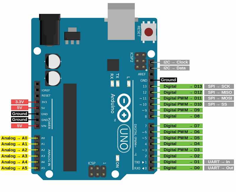
Arduino Uno R3 Pin Details :
The Arduino Uno R3 has various types of pins categorized into Digital I/O, Analog Input, Power, and Communication pins. Here’s a detailed breakdown of each pin’s function and usage.
Digital I/O Pins (D0 - D13)
These pins can be used as either input or output using pinMode().
Operate at 5V logic level and can handle up to 40mA per pin.
Some pins have special functions for communication, PWM, or interrupts.
Pin-by-Pin Explanation
D0 (RX) – Used to receive serial data (UART communication). Avoid using this pin if you're using Serial Monitor.
D1 (TX) – Used to transmit serial data (UART communication). Avoid using this pin if you're using Serial Monitor.
D2 – General-purpose digital I/O. Can also be used as an external interrupt (attachInterrupt()).
D3 – Supports PWM (Pulse Width Modulation) and can be used for motor speed control, LED dimming, etc. Also supports external interrupts.
D4 – General-purpose digital I/O pin.
D5 – Supports PWM. Useful for motor drivers and LED brightness control.
D6 – Supports PWM. Similar to D5, often used in analog output applications.
D7 – General-purpose digital I/O pin.
D8 – General-purpose digital I/O pin.
D9 – Supports PWM. Often used for motor control, servos, and dimming LEDs.
D10 – Supports PWM and also serves as SPI Slave Select (SS) for SPI communication.
D11 – Supports PWM and is used for SPI Master Out Slave In (MOSI) communication.
D12 – Used for SPI Master In Slave Out (MISO) communication.
D13 – Used for SPI Serial Clock (SCK) and also controls the built-in LED on the board.
Analog Input Pins (A0 - A5)
These pins are 10-bit Analog-to-Digital Converters (ADC), meaning they convert analog signals (0-5V) into values between 0-1023.
Can also be used as digital I/O if required.
Pin-by-Pin Explanation
A0 – Reads analog signals, e.g., from sensors like temperature or light sensors.
A1 – Similar to A0, used for measuring varying voltage levels.
A2 – Used for additional sensor readings.
A3 – General-purpose analog input pin.
A4 – Can be used for I2C communication (SDA - Serial Data Line).
A5 – Can be used for I2C communication (SCL - Serial Clock Line).
Power Pins
Used to power the board and connected components like sensors, motors, and displays.
Pin-by-Pin Explanation
VIN – Used to supply external power (7-12V recommended, max 20V). The onboard regulator converts it to 5V.
3.3V – Provides a regulated 3.3V output for low-power components like some sensors.
5V – Provides a regulated 5V output from the onboard voltage regulator.
GND (Ground) – Common ground reference for circuits (Multiple GND pins available).
AREF (Analog Reference) – Used to provide a reference voltage for analog inputs, improving precision.
IOREF – Provides a reference voltage (5V) to shields for compatibility.
Communication Pins
These pins are used for data transmission between the Arduino and other devices (e.g., sensors, displays, computers).
Serial Communication UART ( Universal Asynchronous Receiver Transmitter)
D0 (RX) – Serial receive pin (receives data from another device).
D1 (TX) – Serial transmit pin (sends data to another device).
SPI Communication (Serial Peripheral Interface)
D10 (SS - Slave Select) – Used to select slave devices in SPI communication.
D11 (MOSI - Master Out Slave In) – Sends data from the Arduino to connected SPI devices.
D12 (MISO - Master In Slave Out) – Receives data from an SPI device.
D13 (SCK - Serial Clock) – Provides the clock signal for SPI communication.
I2C Communication (Inter-Integrated Circuit)
A4 (SDA - Serial Data Line) – Used for data exchange in I2C communication.
A5 (SCL - Serial Clock Line) – Generates the clock signal for I2C communication.
Summary
Digital Pins (D0-D13): General-purpose I/O, PWM, interrupts, UART, SPI.
Analog Pins (A0-A5): Read analog sensors, can also be used as digital pins, support I2C.
Power Pins: Provide power to circuits and components (VIN, 3.3V, 5V, GND, AREF).
Communication Pins: Enable Serial (UART), SPI, and I2C communication.
Summary of ESP32-C3 Datasheet
The ESP32-C3 is a cost-effective, low-power, 32-bit RISC-V microcontroller with integrated Wi-Fi and Bluetooth LE 5.0. Designed for secure and efficient IoT applications, it provides robust wireless connectivity and flexible I/O configuration.
Technical Specifications
Microcontroller: 32-bit RISC-V Single-Core CPU
Clock Speed: Up to 160 MHz
SRAM: 400 KB
ROM: 384 KB
Flash: External (typically 4 MB via SPI)
EEPROM: Not available (can be emulated using flash)
Operating Voltage: 3.0V to 3.6V
Input Voltage (recommended): Via 3.3V regulated supply
Wi-Fi: IEEE 802.11 b/g/n (2.4 GHz, up to 150 Mbps)
Bluetooth: Bluetooth 5.0 LE with Mesh and Long Range
Digital I/O Pins: 22 GPIOs
ADC: 12-bit, up to 6 channels
UART: 2
SPI: 2
I2C: 1
PWM: Available on all GPIOs
Timers: Multiple hardware timers
USB: USB 2.0 Full-Speed (native support)
Security: AES, SHA, RSA, ECC, Flash Encryption, Secure Boot
Power Consumption: Active Mode ~130 mA, Light Sleep ~0.8 mA, Deep Sleep ~5 µA
Package: QFN32 (5 mm × 5 mm)
Supported Tools: ESP-IDF, Arduino IDE, PlatformIO, MicroPython
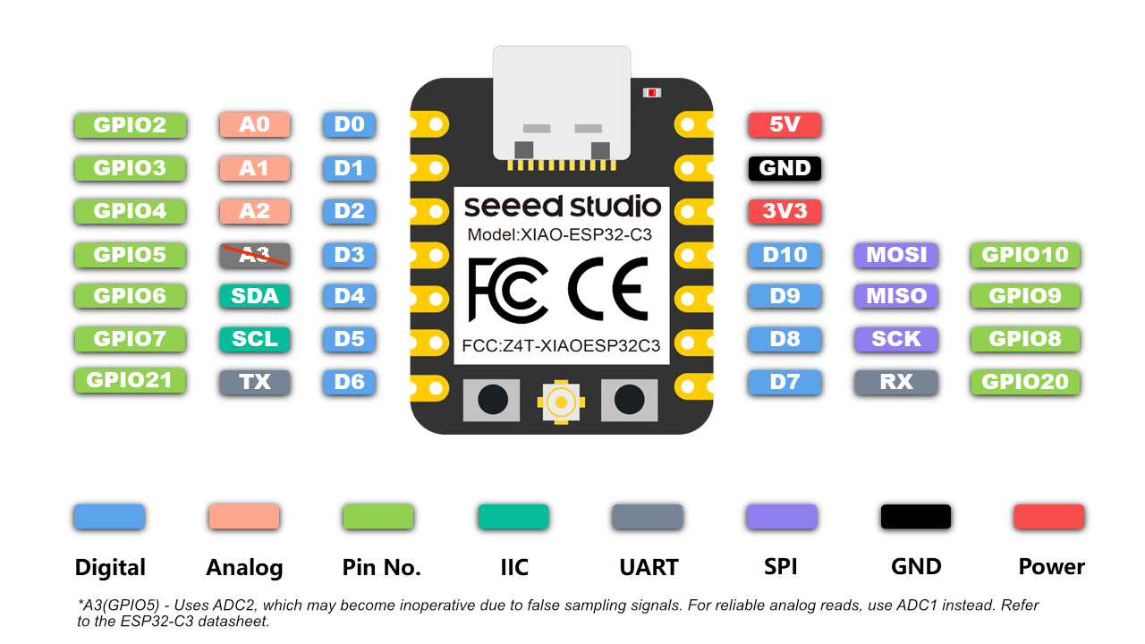
ESP32-C3 Pin Details
The ESP32-C3 supports flexible pin assignment using its GPIO matrix, allowing peripherals to be remapped to available pins as needed.
Digital I/O Pins (GPIO0 to GPIO21)
All GPIOs are multifunctional and support input, output, pull-up/down, PWM, and peripheral mapping. Maximum current draw per GPIO is approximately 20–40 mA depending on usage.
Important GPIOs
GPIO0 – Used for boot mode selection during flashing
GPIO1 and GPIO3 – Default UART TX and RX (avoid using when Serial Monitor is active)
GPIO9 and GPIO10 – Usually connected to internal flash, should not be used for I/O
GPIO19 and GPIO20 – USB D- and D+ on some modules
Analog Input Pins (ADC1 Channels)
ESP32-C3 has 6 ADC1 channels with 12-bit resolution, mapped to GPIOs like GPIO0 to GPIO5. These are used for reading analog voltages from 0 to 3.3V.
Power Pins
3V3 – Regulated 3.3V power input
GND – Ground reference
EN – Chip enable (reset if pulled low)
VBUS – USB power input (5V on USB)
LDO Cap – Capacitor pin for internal LDO regulator (used in specific modules)
Communication Pins
Serial (UART):
Default UART uses GPIO1 (TX) and GPIO3 (RX). UARTs can be remapped to other pins using software.
SPI:
SPI0 is reserved for internal flash. SPI1 is available for general-purpose communication and can be mapped to any free GPIOs.
I2C:
Supports one I2C controller in master/slave mode. SDA and SCL lines can be assigned to most GPIOs. Common assignments are GPIO4 (SDA) and GPIO5 (SCL).
USB:
Native USB 2.0 interface supported on modules like ESP32-C3-DevKit. D+ and D- are usually mapped to GPIO19 and GPIO20.
Security Features
Hardware-based Flash Encryption
Secure Boot (version 2)
Cryptographic acceleration for AES-128/256, SHA-2, RSA-3072, and ECC
Digital Signature Peripheral
Summary
Digital Pins (GPIO0–GPIO21): General-purpose I/O with PWM and peripheral mapping
Analog Pins: 6 channels of 12-bit ADC
Power Pins: 3.3V input, multiple GND, EN, USB VBUS
Communication Interfaces: UART, SPI, I2C, USB
Connectivity: Integrated Wi-Fi (2.4 GHz) and Bluetooth 5.0 LE
Security: Supports advanced encryption, secure boot, and digital signature
Power Modes: Active (~130 mA), Light Sleep (~0.8 mA), Deep Sleep (~5 µA)
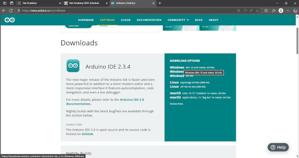
For coding and uploading programs to my microcontroller, I am using the Arduino IDE. It is a user-friendly open-source platform that supports various boards like the ESP32-C3. With the help of its built-in libraries and community support, I can easily write, verify, and upload code to test different hardware functionalities
Wokwi is an online simulator designed for developing and testing Arduino, ESP32, Raspberry Pi Pico, and other microcontroller-based projects. It allows users to create circuits, write code, and see real-time simulations in a browser without the need for physical hardware. Wokwi supports popular components like LEDs, sensors, displays, and more, making it an excellent tool for prototyping and learning embedded systems quickly and interactively.
As part of the embedded programming assignment, I worked with the ESP32-C3 module integrated with the MPU6050 sensor. I explored I2C communication to read accelerometer and gyroscope data. This setup helped me understand real-time motion sensing and sensor interfacing, laying the foundation for integrating it into my final project.
To interface the MPU6050 sensor with my ESP32-C3 board, I used the Adafruit MPU6050 library in the Arduino IDE. This library simplifies communication with the sensor by providing easy-to-use functions for accessing accelerometer and gyroscope data. After installing the library through the Library Manager, I was able to write and upload code to read motion and orientation values effectively.
Arduino library for the MPU6050 sensors
             #include <Adafruit_MPU6050.h> // Include the library for MPU6050 sensor
#include <Adafruit_Sensor.h>   // Include Adafruit sensor support
#include <Wire.h>              // I2C communication library
Adafruit_MPU6050 mpu;          // Create an MPU6050 sensor object
sensors_event_t event;         // Define a variable to hold sensor data
void setup() {
  Serial.begin(115200);       // Start serial communication at 115200 baud
  pinMode(D2, OUTPUT);        // Set pin D2 as OUTPUT (e.g., for LED or other output)
  pinMode(D3, OUTPUT);        // Set pin D3 as OUTPUT
  Serial.println("");
  Serial.println("Hello, XIAO ESP32-C3!"); // Welcome message
  Serial.println("Welcome to Wokwi :-)");
  while (!mpu.begin()) {      // Keep trying until MPU6050 initializes
    Serial.println("MPU6050 not connected!"); // Error message
    delay(1000);              // Wait for 1 second before retrying
  }
  Serial.println("MPU6050 ready!"); // MPU6050 successfully initialized
}
void loop() {
  // The following commented lines were for testing LEDs on different pins
  // Serial.println("Red");
  // digitalWrite(D2, HIGH);   // Turn on LED on D2
  // delay(500);               // Wait for 0.5 seconds
  // digitalWrite(D2, LOW);    // Turn off LED
  // Serial.println("Green");
  // digitalWrite(D3, HIGH);   // Turn on LED on D3
  // delay(500);
  // digitalWrite(D3, LOW);    // Turn off LED
  // Serial.println("Blue");
  // digitalWrite(D4, HIGH);   // This line would cause an error unless D4 is defined
  // delay(500);
  // digitalWrite(D4, LOW);
  mpu.getAccelerometerSensor()->getEvent(&event); // Read acceleration data
  Serial.print("[");
  Serial.print(millis());           // Print current time in milliseconds
  Serial.print("] X: ");
  Serial.print(event.acceleration.x); // Print X-axis acceleration
  Serial.print(", Y: ");
  Serial.print(event.acceleration.y); // Print Y-axis acceleration
  Serial.print(", Z: ");
  Serial.print(event.acceleration.z); // Print Z-axis acceleration
  Serial.println(" m/s^2");         // Print units
  delay(500);                       // Wait for half a second before next reading
}
To assist with embedded programming, I utilized AI coding tools to help write and debug the code for interfacing the ESP32-C3 with the MPU6050 sensor. These tools provided suggestions, reduced development time, and improved accuracy in setting up I2C communication, making the programming process more efficient and insightful.