Group assignment
Individual assignments

Molding and casting is a versatile manufacturing process used to replicate objects by creating a mold of a desired shape and then filling it with a casting material. This technique is widely used in industries for prototyping and production, allowing the creation of complex geometries with precision and repeatability in various materials.
Molding and casting are fundamental manufacturing processes used to create parts and prototypes by shaping materials inside a mold. Depending on the application, material, and production scale, different techniques are used. Below are some of the most commonly used types of molding and casting:
Compression Molding
This process involves placing a preheated material (usually a thermoset plastic) into a heated mold cavity. The mold is then closed and pressure is applied to force the material to conform to the mold shape. It is commonly used for making automotive parts, electrical components, and kitchenware.
Advantages: Low waste, good for large parts
Disadvantages: Slower process, limited to simple shapes
Injection Molding
Injection molding involves injecting molten material (usually plastic) under high pressure into a mold cavity. It is widely used in mass production of plastic products like bottle caps, toys, and phone cases.
Advantages: Fast, high precision, ideal for mass production
Disadvantages: High initial tooling cost
Blow Molding
Used primarily for making hollow plastic parts like bottles. A heated plastic tube is inflated inside a mold so it takes the shape of the mold cavity.
Advantages: Good for hollow objects, fast
Disadvantages: Limited to hollow shapes
Rotational Molding
In this process, a powdered plastic is placed inside a mold which is then rotated in multiple axes while being heated. The powder melts and coats the inside of the mold evenly.
Advantages: Uniform wall thickness, low tooling cost
Disadvantages: Slow, not ideal for fine details
Sand Casting
A traditional and widely used method where molten metal is poured into a sand mold. After solidification, the mold is broken to retrieve the part.
Advantages: Cost-effective, suitable for large parts
Disadvantages: Rough surface finish, less dimensional accuracy
Investment Casting (Lost Wax Casting)
A wax model of the part is made and coated with a ceramic shell. The wax is melted out, and molten metal is poured into the cavity. It’s used for complex shapes with fine details.
Advantages: High precision, good surface finish
Disadvantages: Expensive and time-consuming
Die Casting
Involves forcing molten metal under high pressure into a steel mold. It is mostly used for mass production of non-ferrous metal parts like zinc, aluminum, and magnesium components.
Advantages: Excellent dimensional accuracy, fast
Disadvantages: High setup cost, limited to non-ferrous metals
Plaster Casting
Similar to sand casting, but uses plaster instead of sand to make the mold. It’s good for casting non-ferrous metals and achieving better surface finish.
Advantages: Good for intricate details
Disadvantages: Weaker mold, limited to low-temperature metals
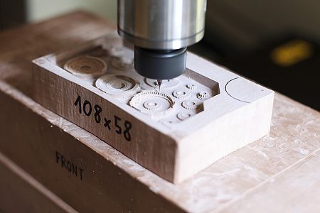
CNC machining is a subtractive process where a mold is carved from a solid block using computer-controlled cutting tools. It ensures high accuracy and repeatability, making it ideal for creating detailed and durable molds. Materials like wax, foam, or aluminum are commonly used depending on the casting material and application.
Material Preparation
Material preparation is a crucial step in molding and casting. It involves selecting suitable materials for both mold and cast, ensuring they are clean, dry, and properly mixed. Accurate measurement and thorough mixing of components like resins or silicones help prevent curing issues and ensure a smooth, high-quality final product.
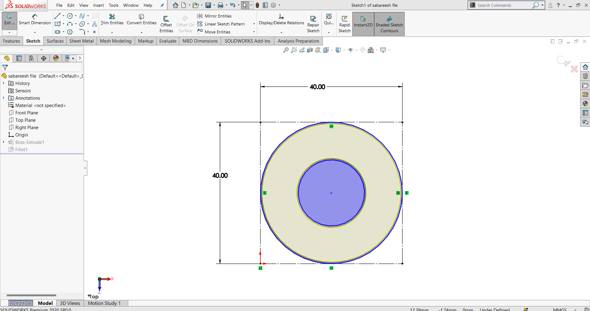
For this assignment, I created a chocolate mold through a series of digital fabrication steps. I began by designing a solid model of a circular object in SolidWorks. Then, using ArtCAM, I generated a 3D milling toolpath to prepare the design for machining, ensuring precise dimensions and smooth contours.
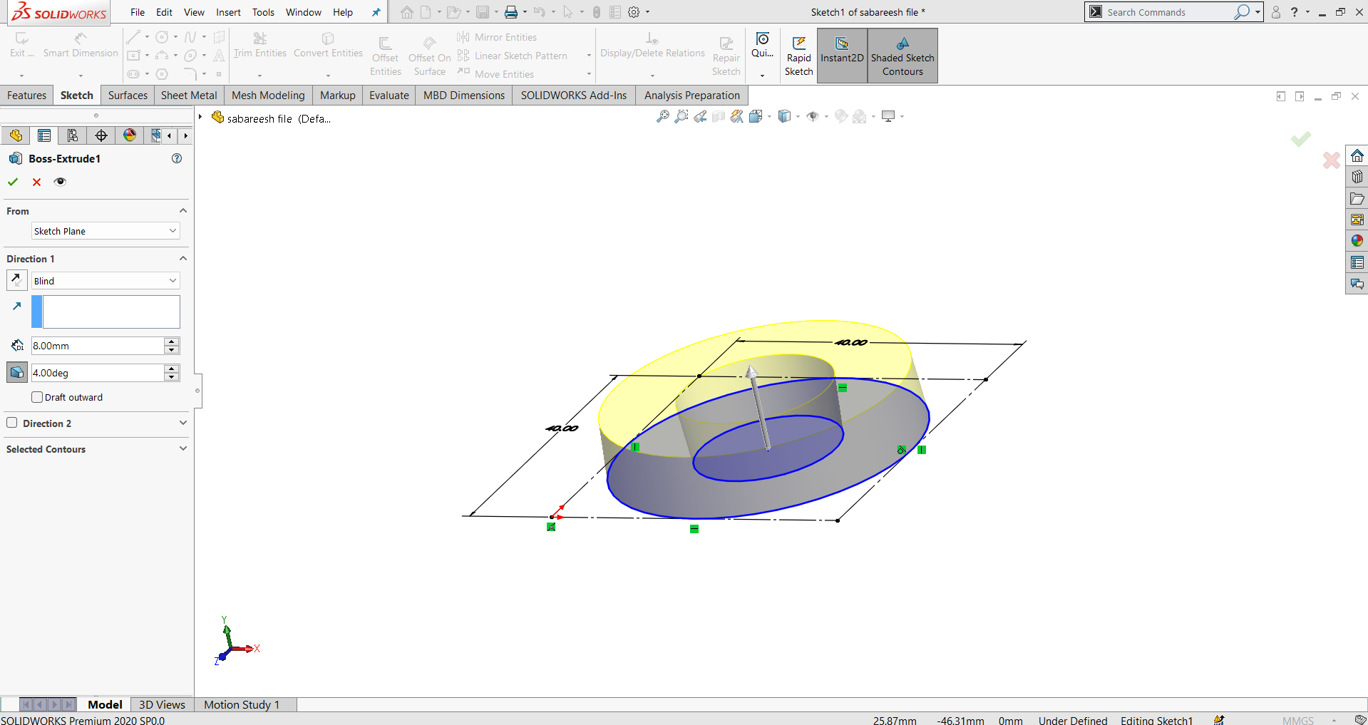
During the Extrude feature in SolidWorks, I applied a 4-degree draft angle to the vertical walls of the model. This draft is essential to ensure the casted chocolate product can be easily released from the mold without damaging the design or causing sticking during the demolding process.
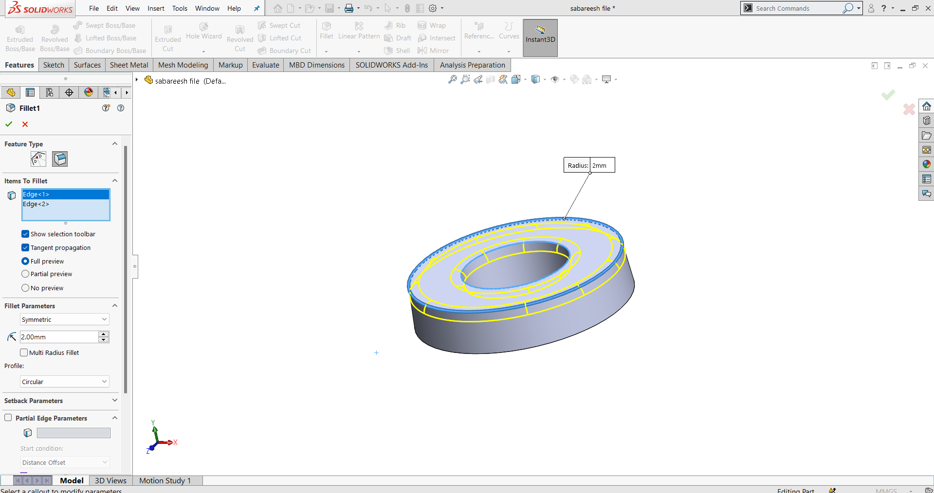
To avoid sharp corners that could hinder mold release or damage the cast, I added fillets to all necessary edges. However, the parting line edge was left without fillets or chamfers to maintain a clean mold separation. Finally, the completed model was exported in STL format for machining.

Here is the final designed output of the chocolate mold. The model includes smooth filleted edges, a proper 4-degree draft for easy release, and a clean parting line for accurate mold separation. It has been carefully prepared and exported in STL format, ready for the 3D milling and molding process.
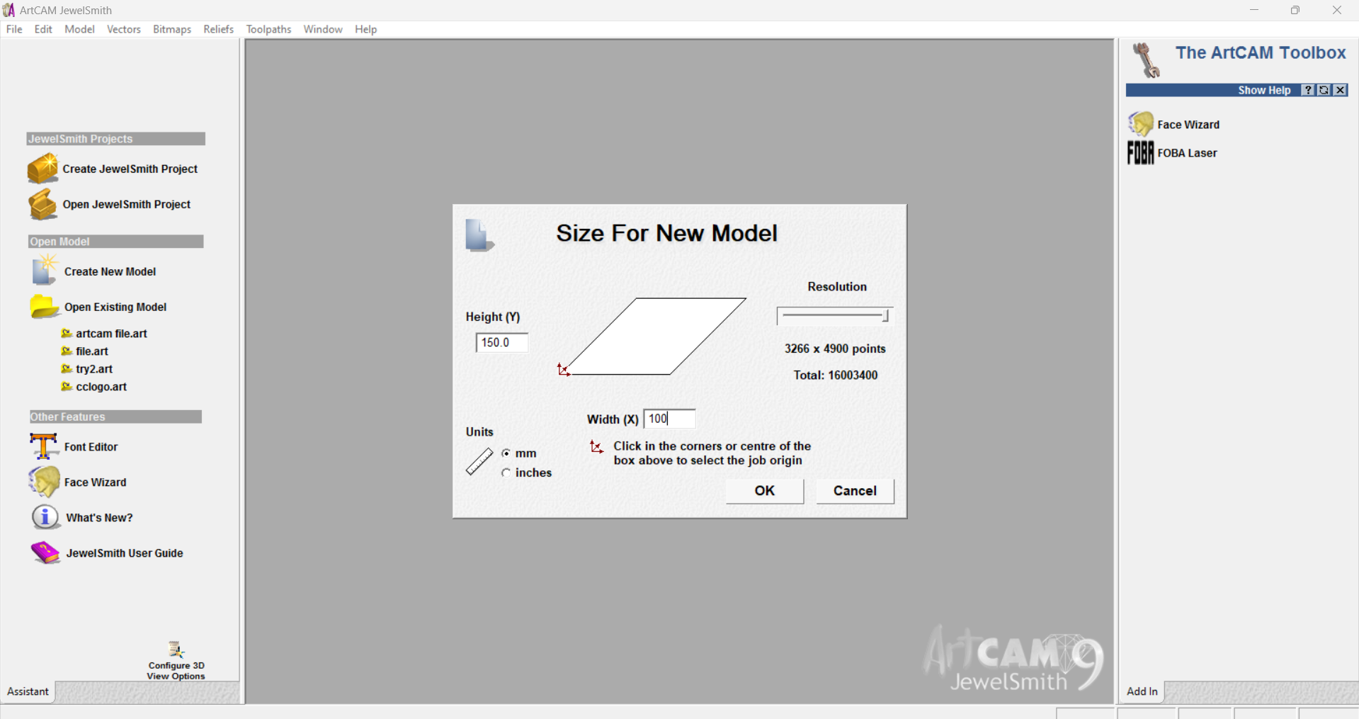
For the milling process, MDF (Medium-Density Fiberboard) was selected as the base material due to its smooth surface and ease of machining. The toolpath was generated using ArtCAM to match the 3D model. The dimensions of the workpiece were set to 100x150 mm, ensuring enough space for the mold design.
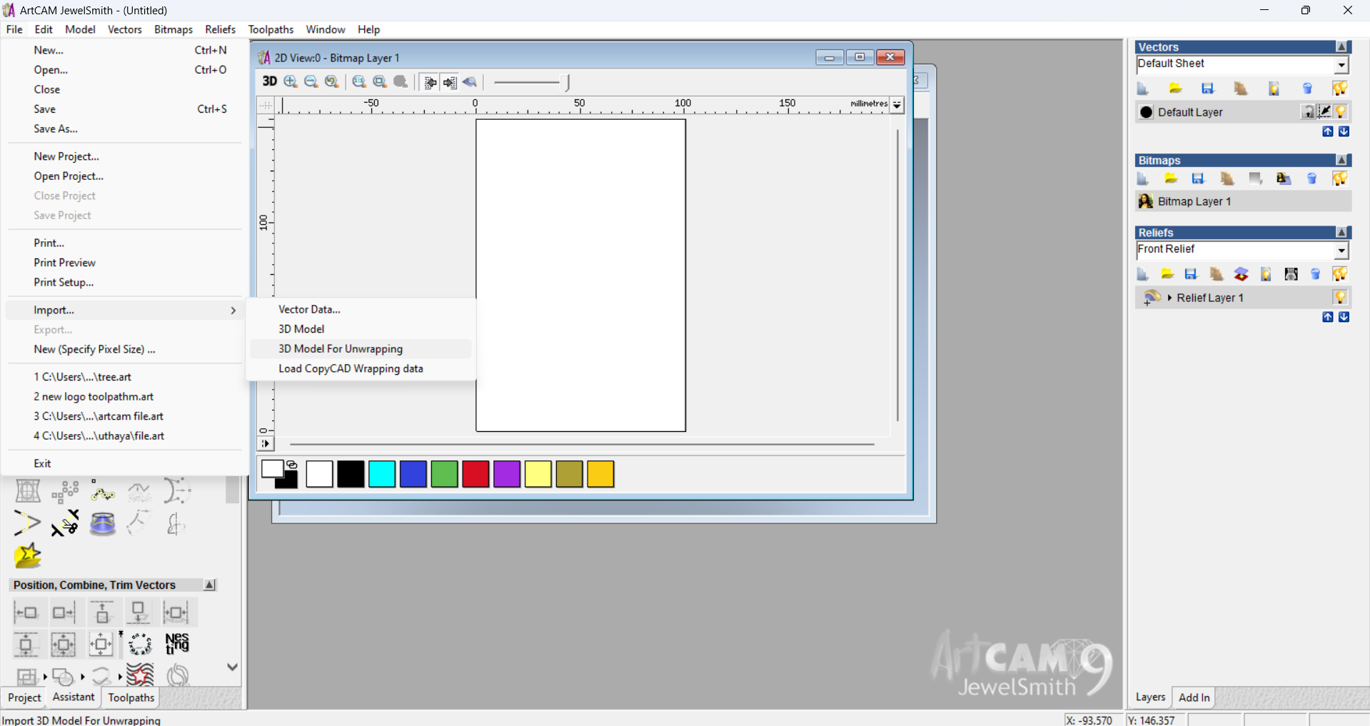
The first step in ArtCAM is to save the relief layer, which stores the 3D surface data. After that, the STL file of the designed model is imported into the software. This imported 3D model is essential for generating an accurate 3D toolpath that guides the milling process.
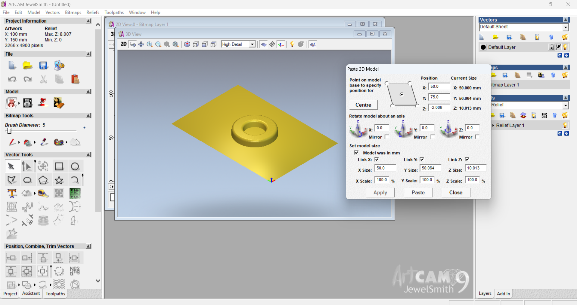
After importing the STL file, the next step is aligning the model to the center of the workpiece in ArtCAM. This ensures that the milling is symmetrical and properly positioned within the 100x150 mm MDF board, preventing any part of the design from being cut off or misaligned during machining.
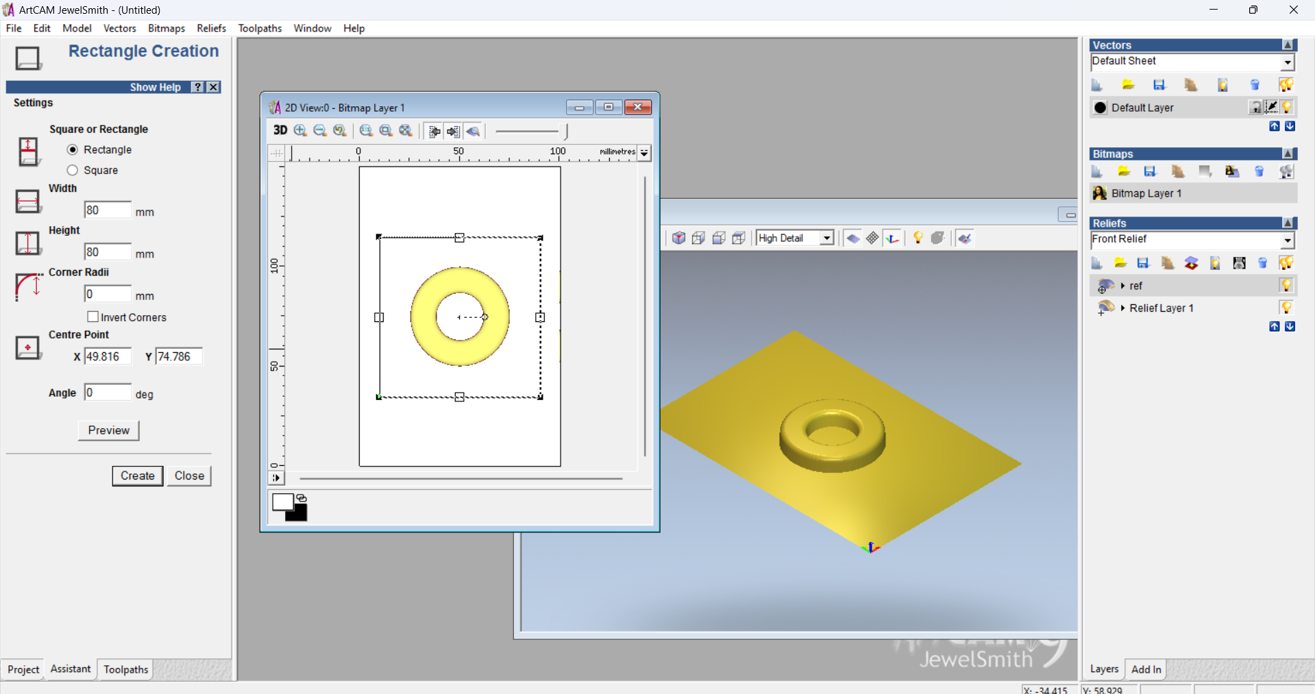
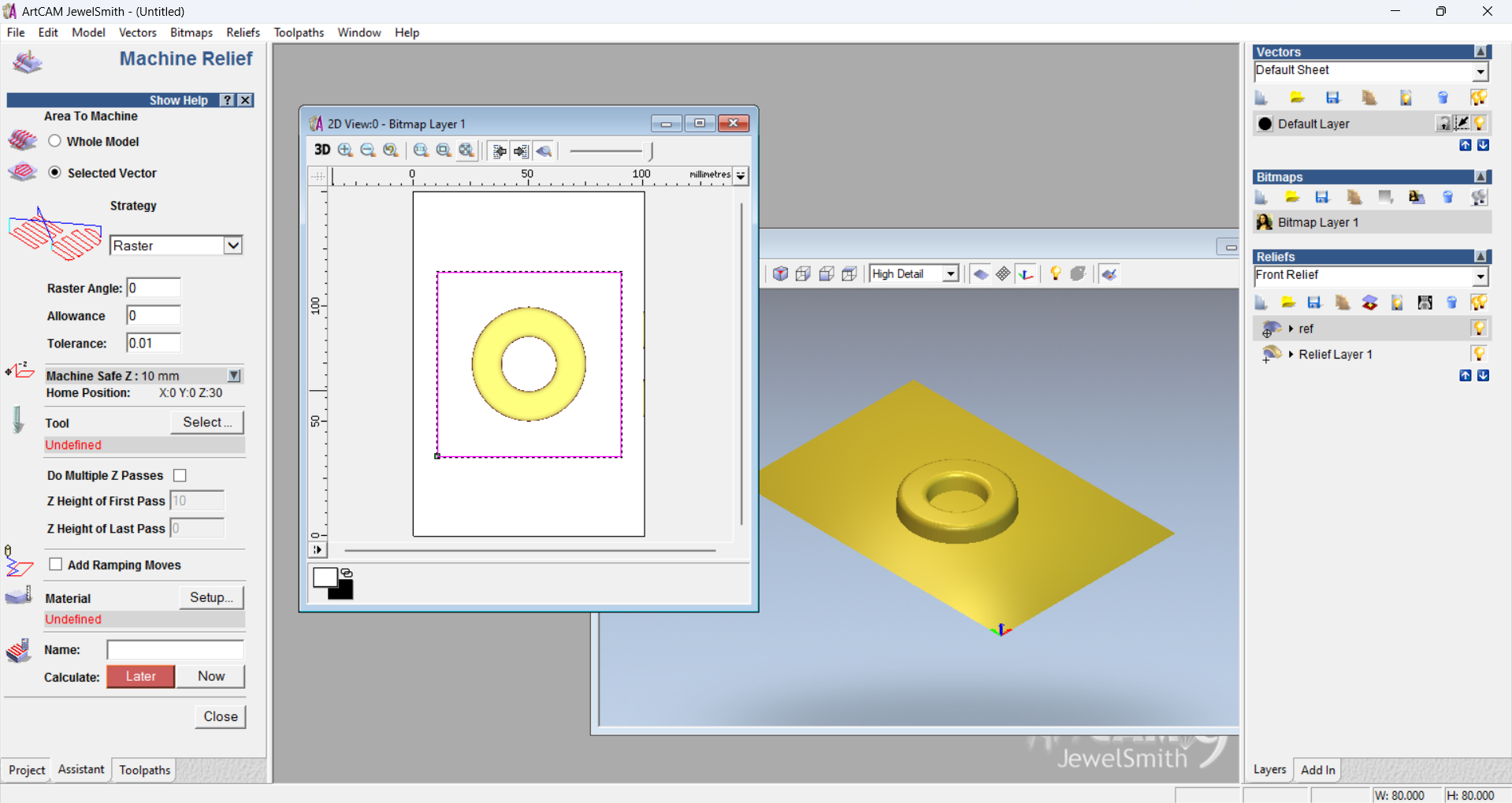
To define the boundary for the mold cavity, I created a rectangle with dimensions 80×80 mm in ArtCAM. This rectangle represents the negative space where the model will be milled out of the MDF block. It serves as the limit for the toolpath, ensuring precise and clean mold boundaries.
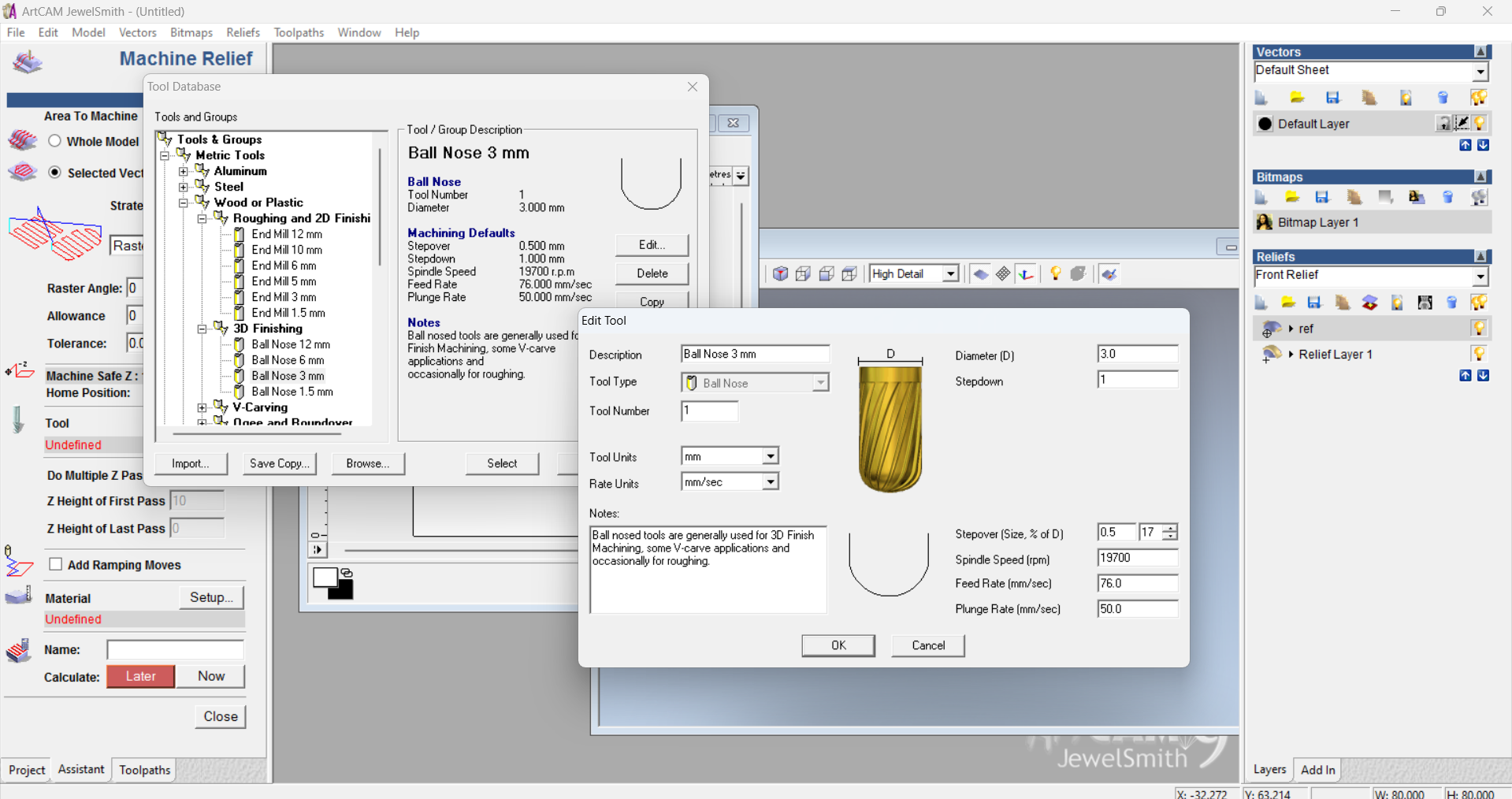
Then, I selected a 3 mm ball nose bit as the milling tool. This tool is ideal for 3D surface machining, allowing smooth curves and detailed contours to be milled accurately. The ball nose bit ensures the fine details of the chocolate mold are preserved during the roughing and finishing operations.
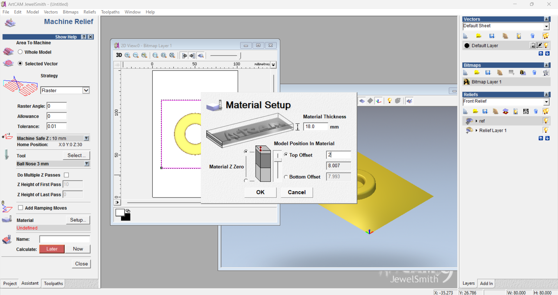
Next, I performed the material setup in ArtCAM. This involved defining the material thickness, setting the origin (usually at the top surface and center or corner of the block), and confirming the Z-zero position. Accurate material setup ensures the toolpath aligns perfectly with the MDF block and avoids any milling errors.
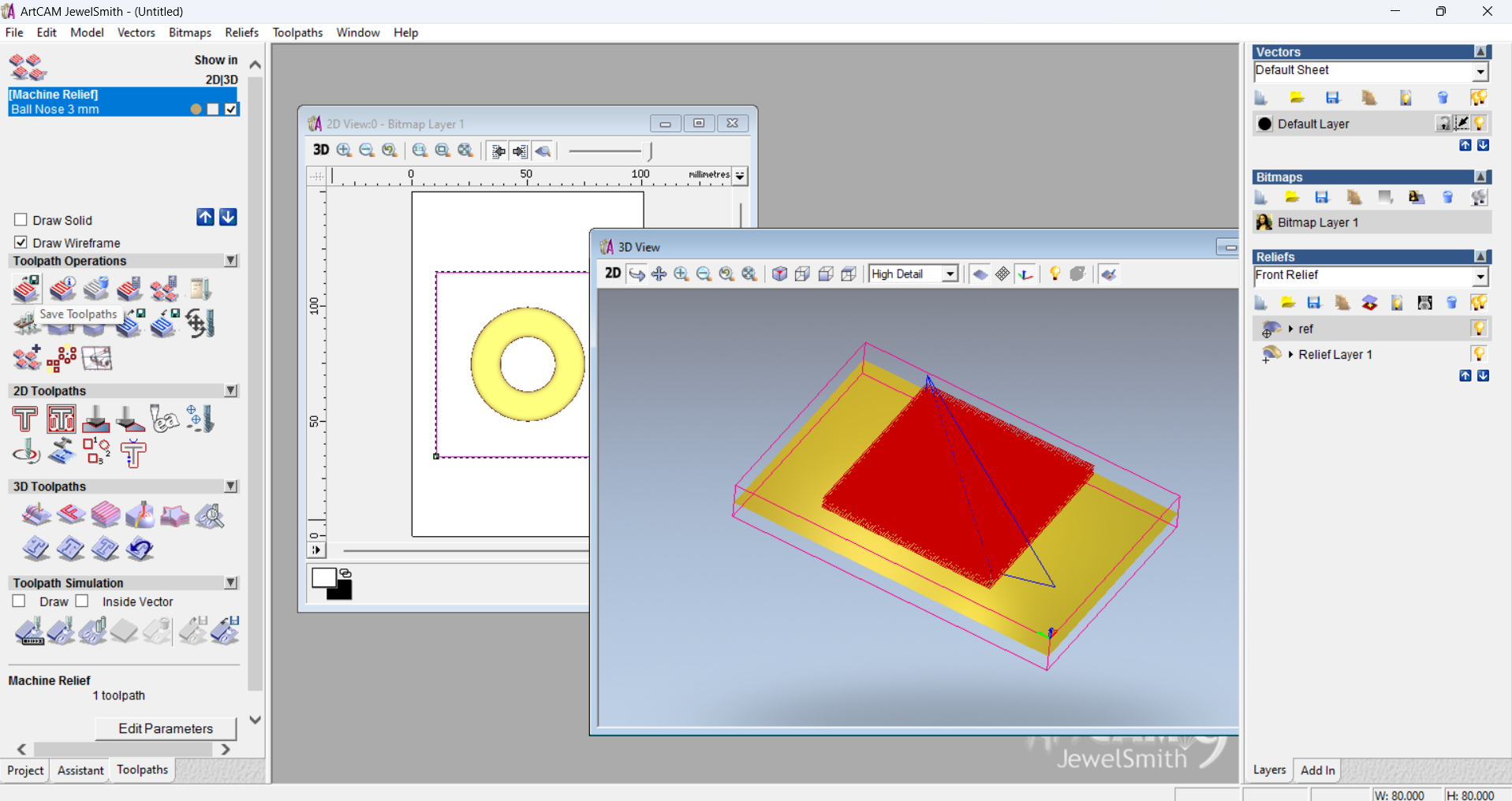
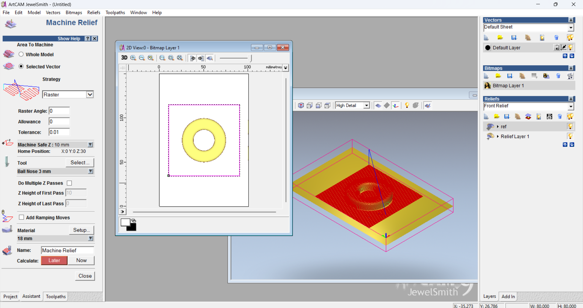
Then, I generated the toolpath for mold creation using the 3D roughing and finishing strategies in ArtCAM. The roughing pass removed excess material, while the finishing pass captured fine details of the design. These toolpaths were based on the imported STL model and ensured precise and smooth milling on the MDF surface.
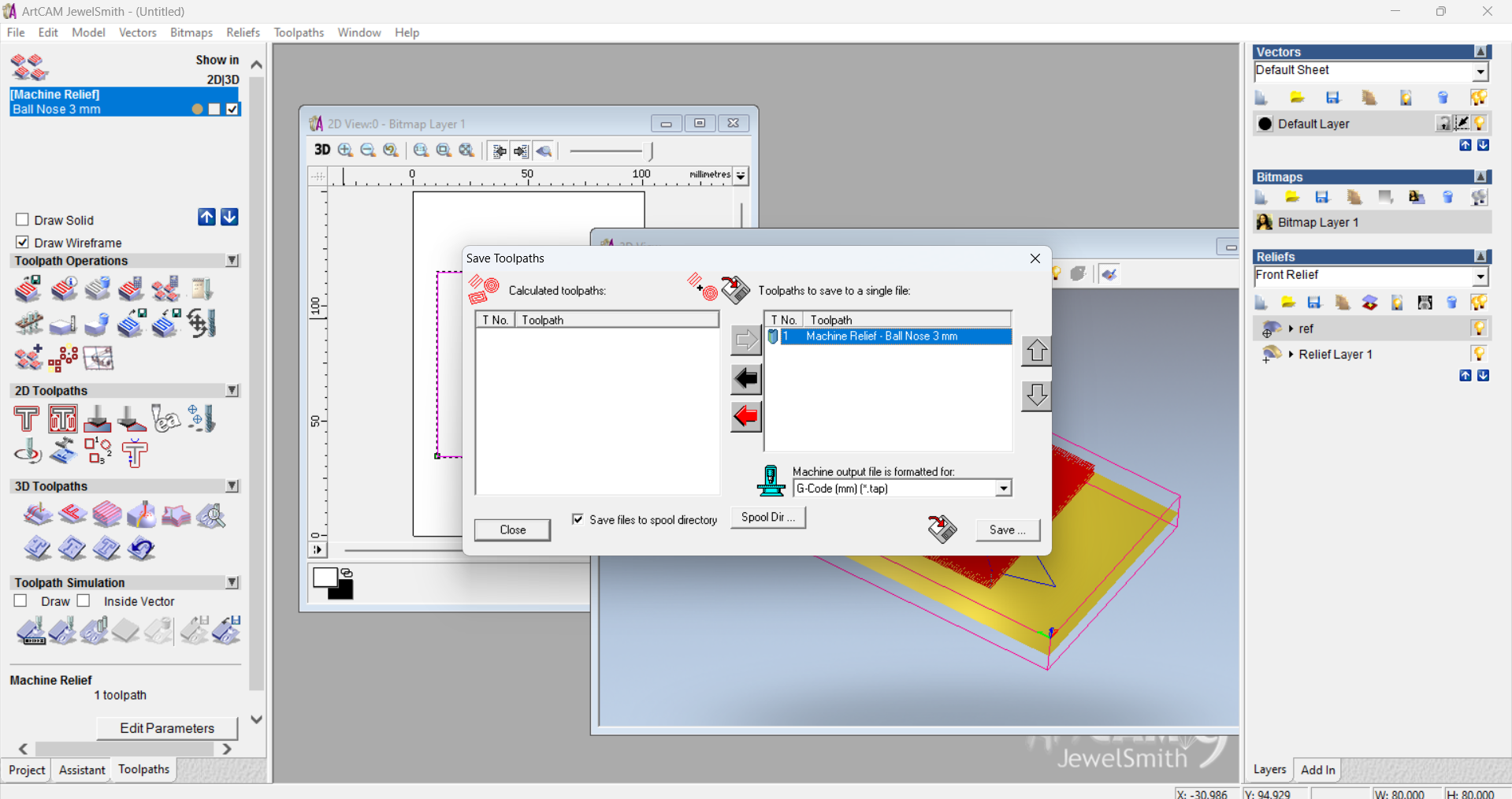
Then, I exported the NC (Numerical Control) file, which contains the machine-readable instructions for the CNC router to execute the milling process. This file was generated from the finalized toolpath settings in ArtCAM.
The NC file is attached below to be used directly with the milling machine for mold creation.
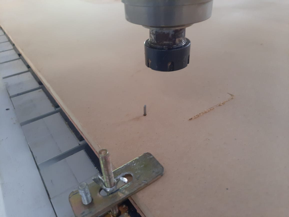
We tried to mill the mold, but unfortunately, the mill bit broke due to excessive cutting depth. To avoid further delays and material waste, I decided to switch to the 3D printing method for mold fabrication. This alternative allowed for precise detailing and faster production using PLA material.
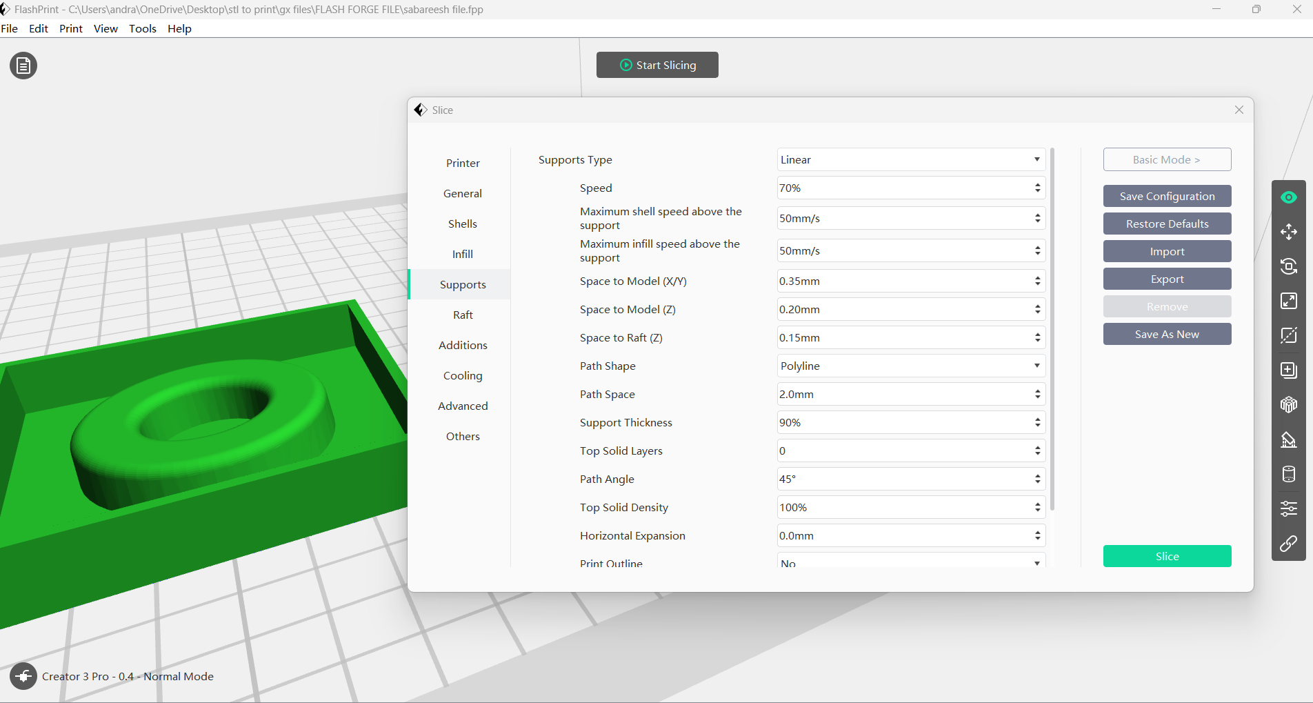
I imported the STL file from SolidWorks into the slicing software and optimized the print settings. To achieve a smoother surface finish, I set the layer height to 0.1 mm. This fine resolution helps capture detailed contours of the mold, ensuring better quality and precision in the final 3D printed part.
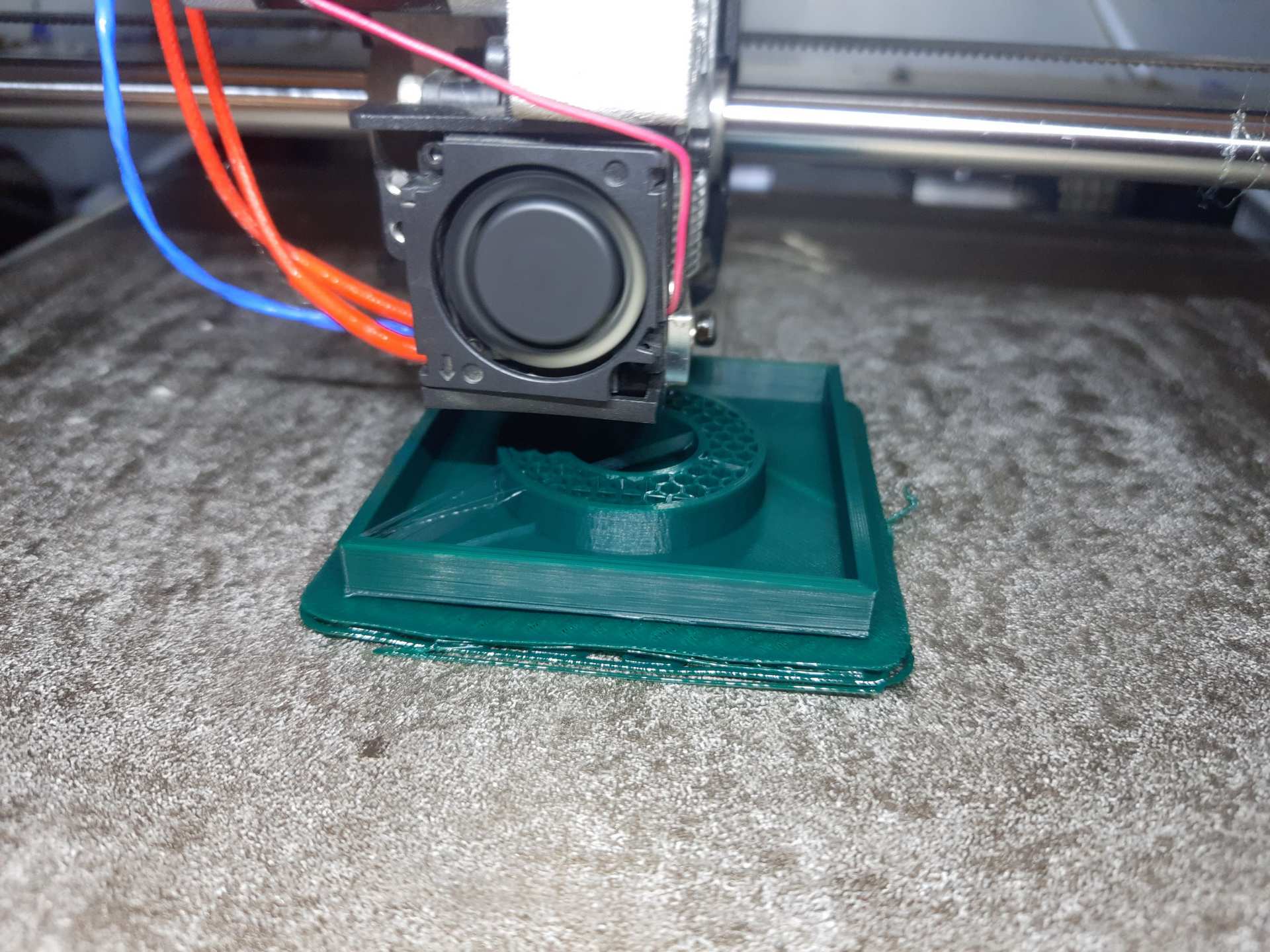
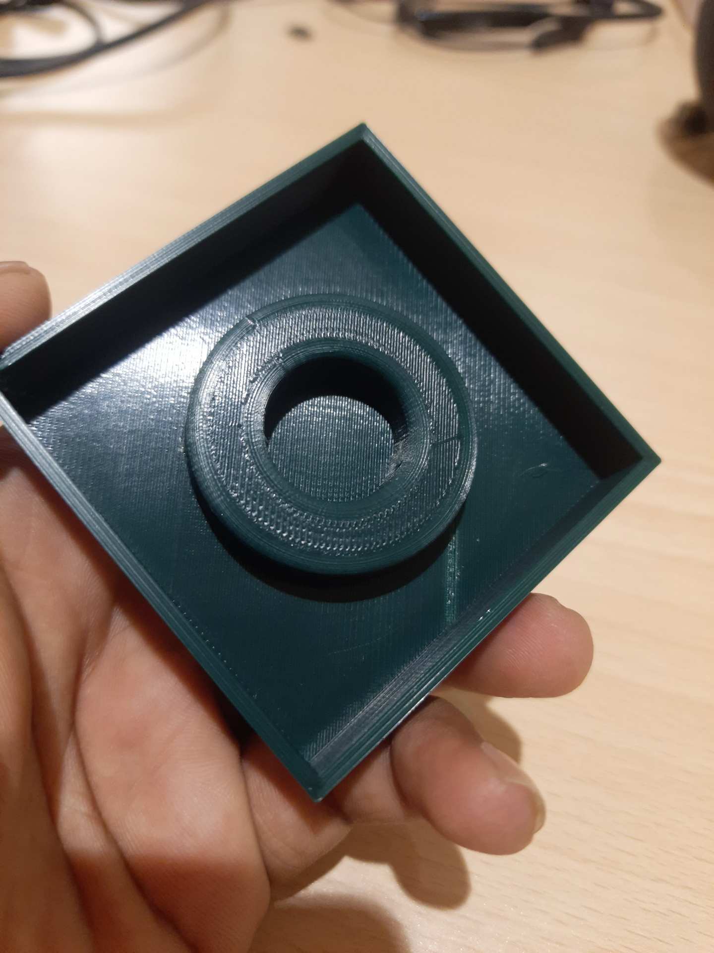
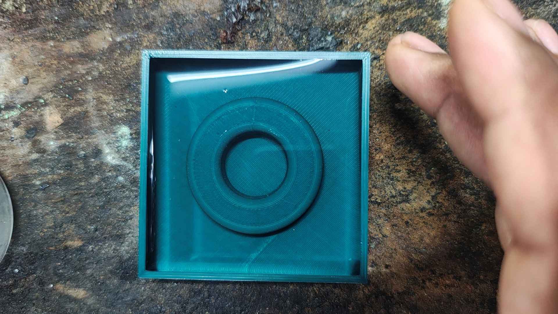
The final mold was successfully 3D printed using PLA material. The print captured fine details accurately, thanks to the 0.1 mm layer height setting.
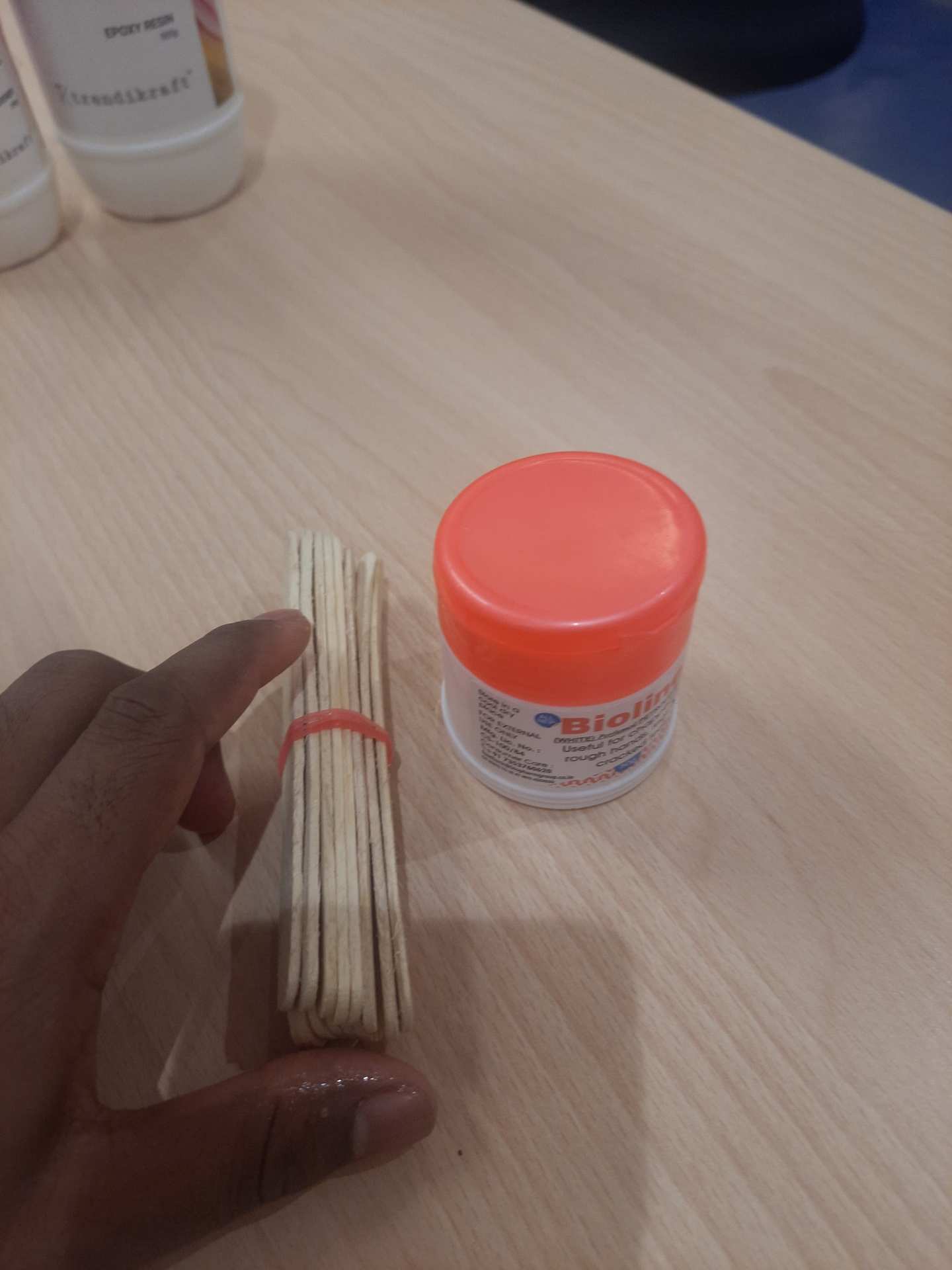
Basic required Components
For mold preparation, the first step was to measure how much silicone material would be required for the negative mold. To do this, I filled the 3D printed cavity with water and then measured the volume of the water used. This gave an accurate estimate of the silicone quantity needed for casting.
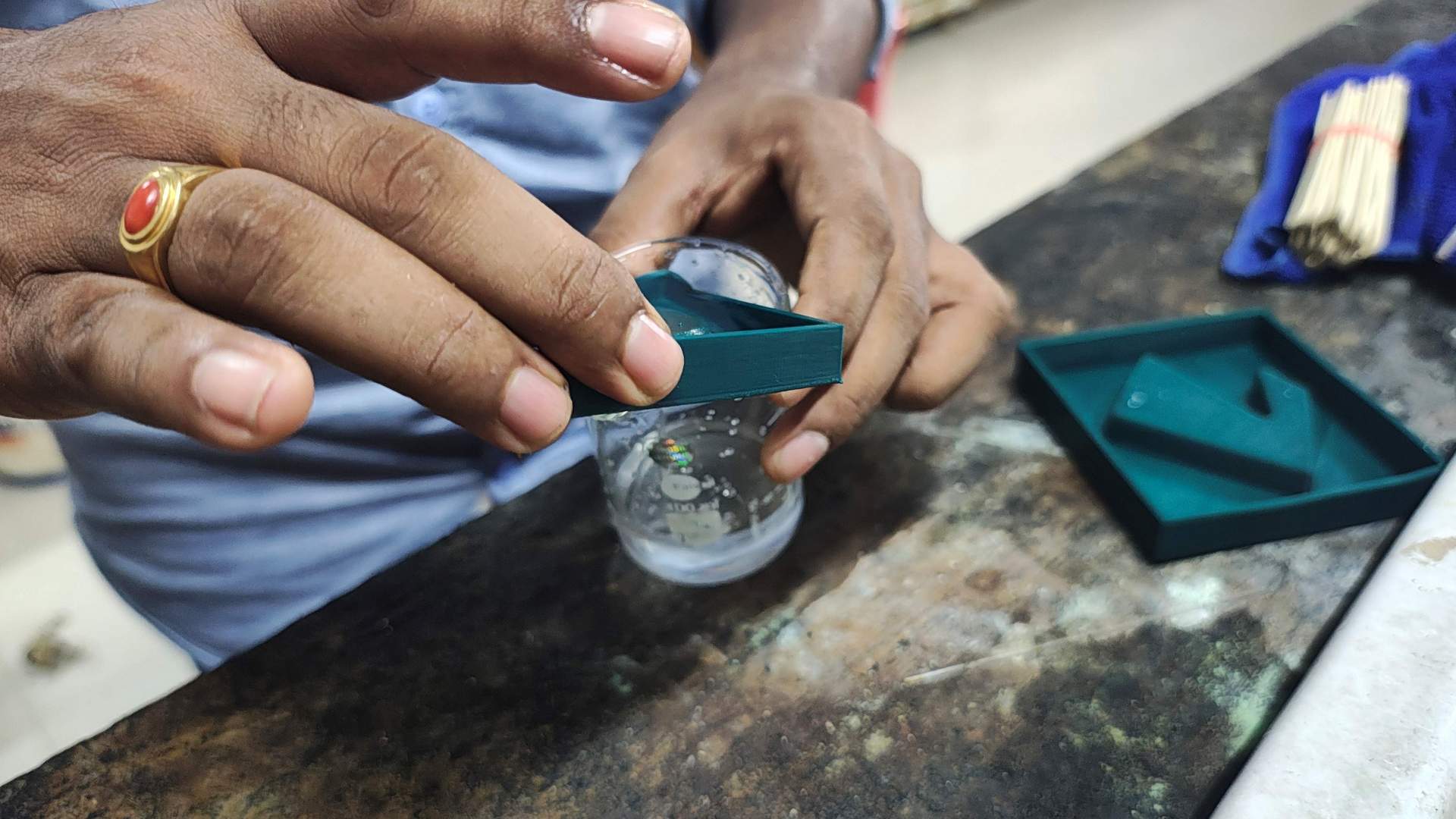
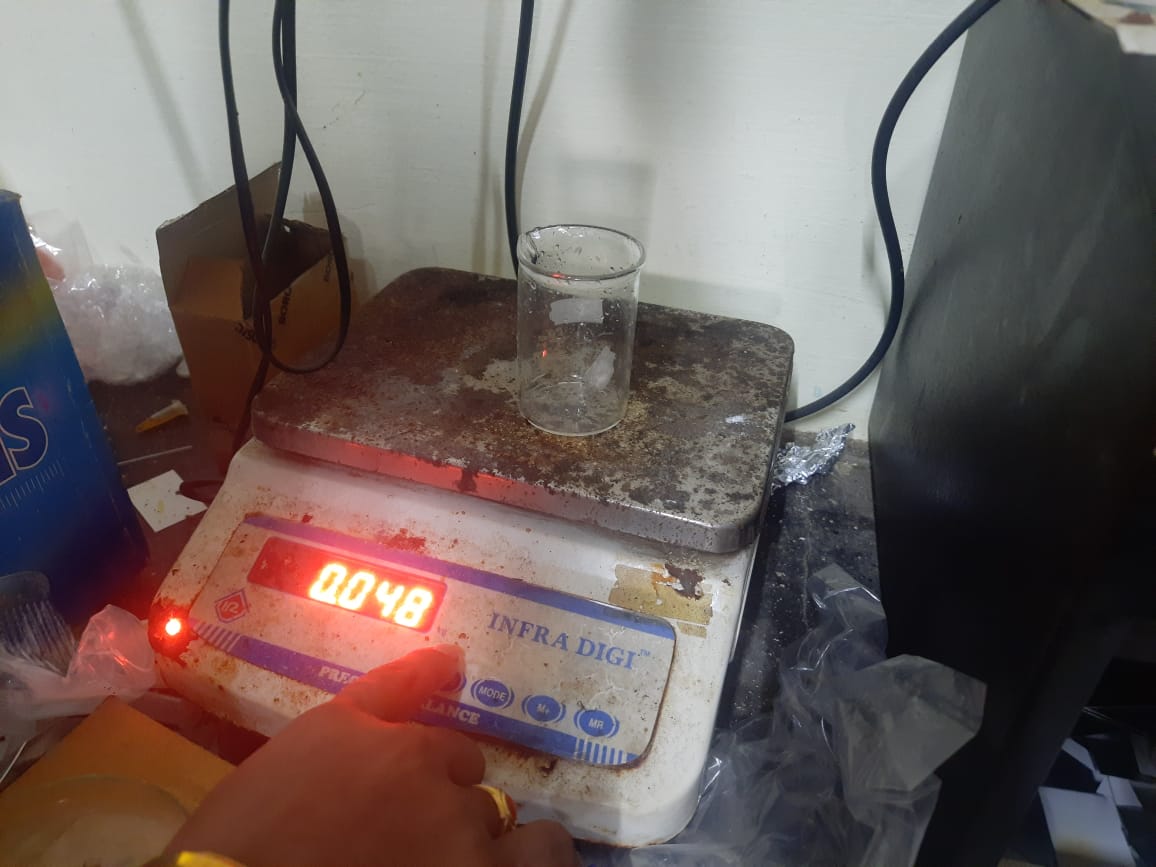
Then, I poured the water into a 250 ml measuring beaker to determine the volume. This allowed me to accurately measure the required amount of silicone for mold making. Based on the reading, I prepared the silicone mixture accordingly to ensure a proper fill without excess or shortage.
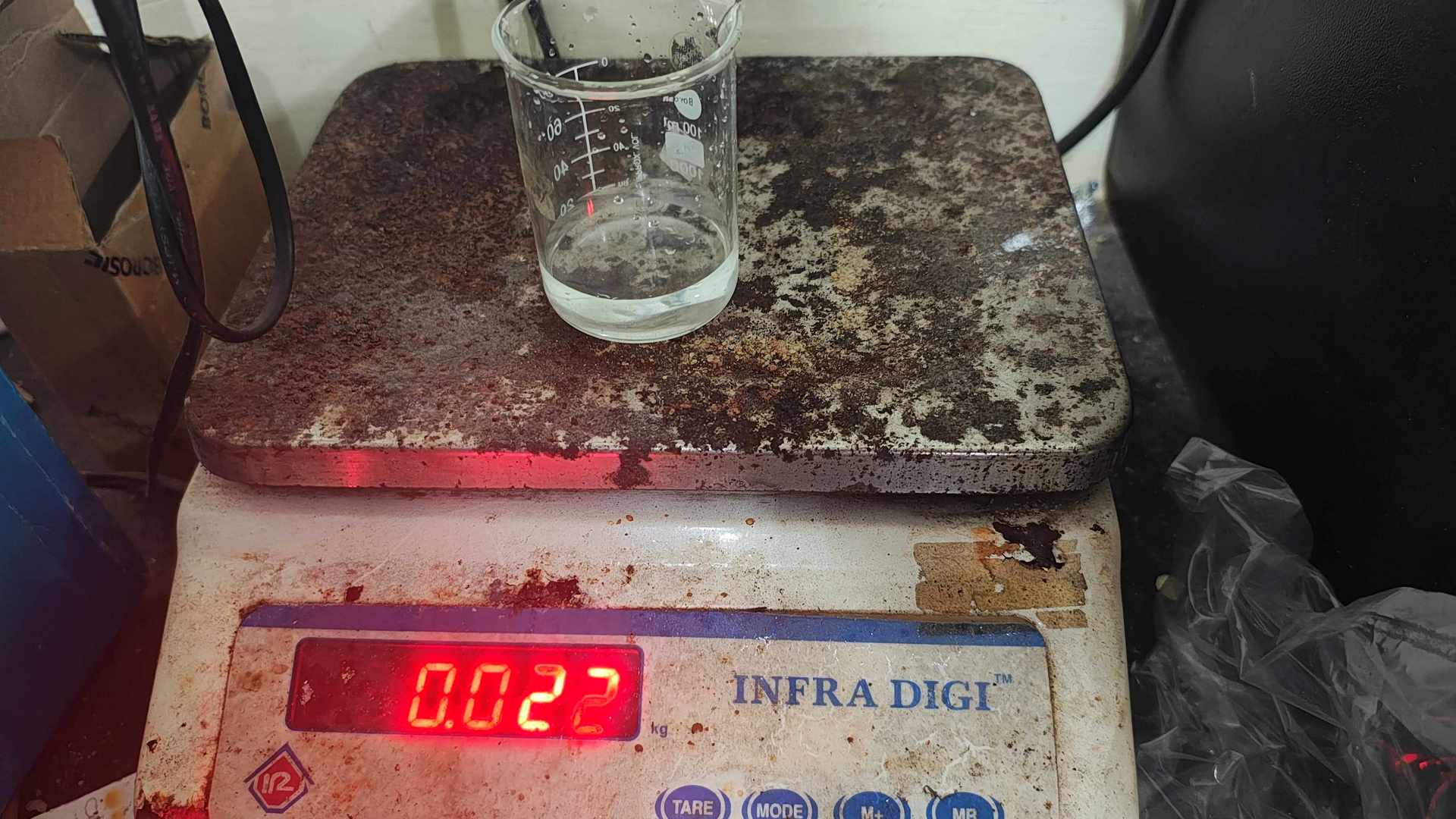
Before measuring the water content, I tared the 250 ml beaker by noting its empty weight. This step ensured that only the actual volume of water was measured accurately. After taring, I poured the water from the mold into the beaker to determine the exact amount of silicone needed.
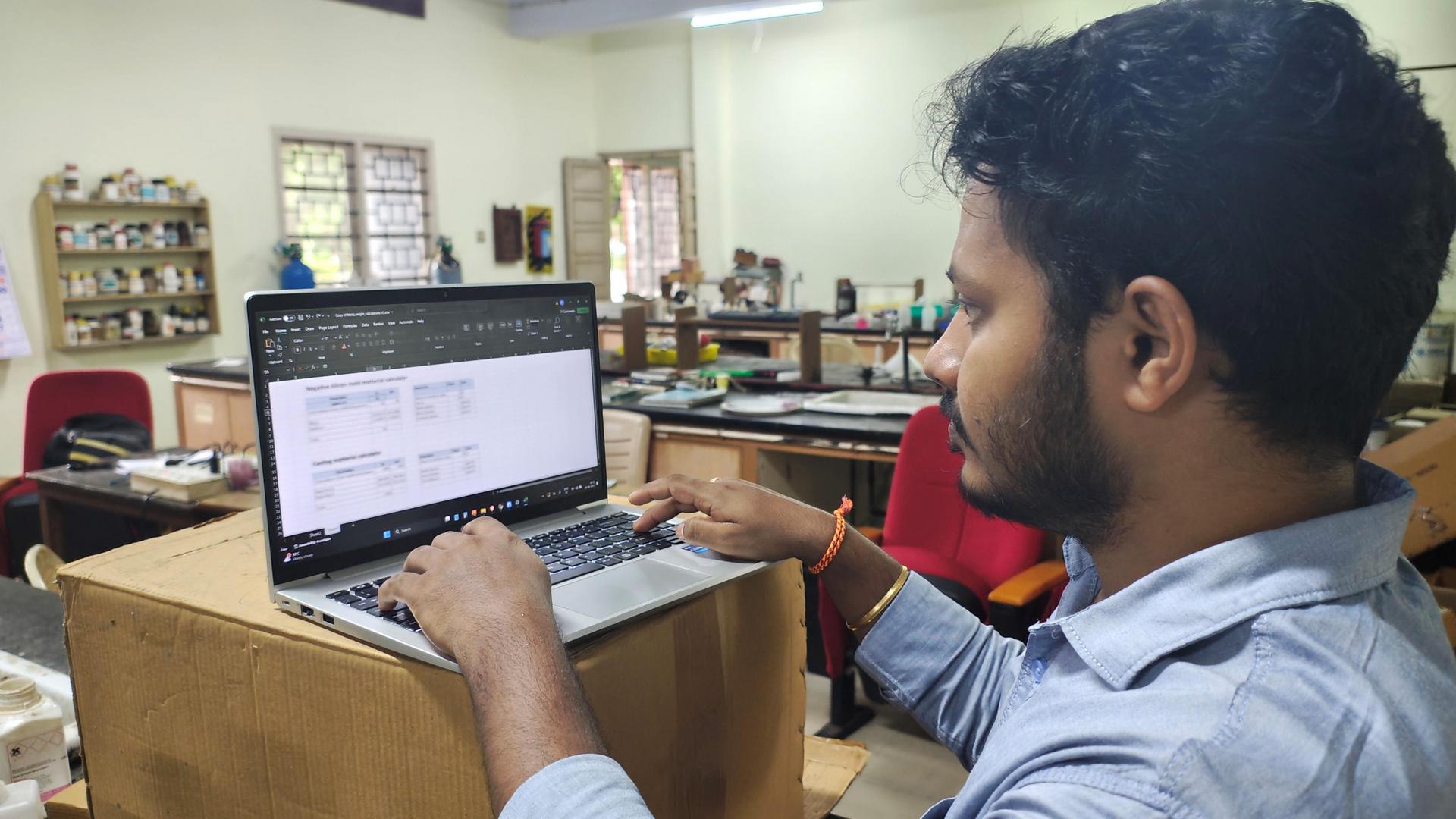
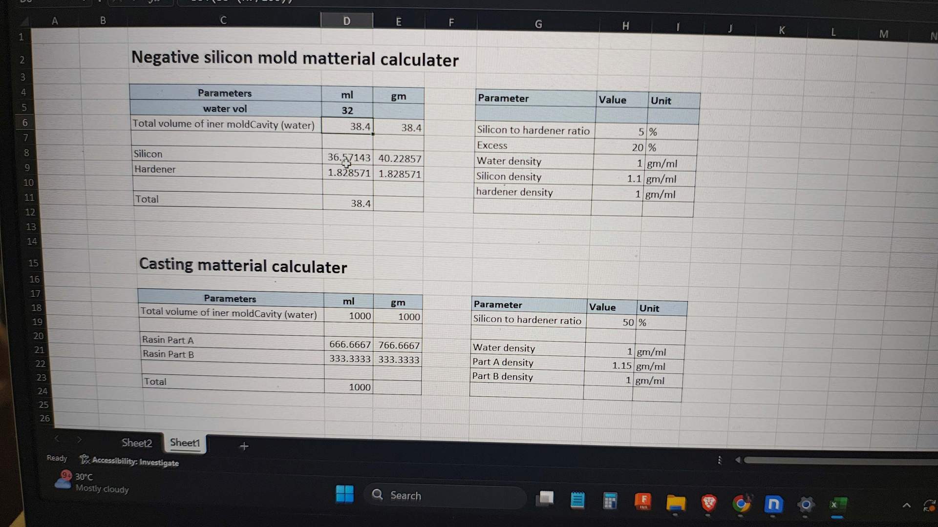
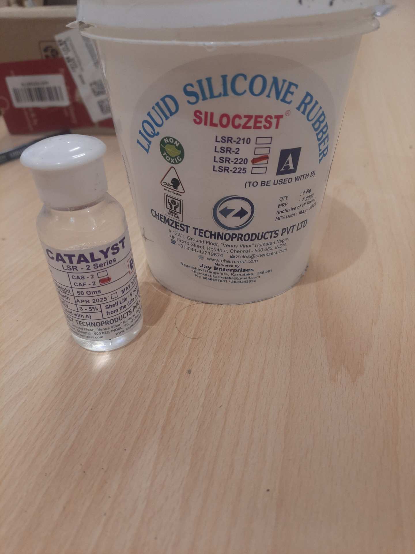
I calculated the required amounts of silicone base and catalyst using the volume measured and an online silicone mold calculator. Based on the water volume, the calculator provided the exact ratio and quantity needed for both components. This ensured accurate mixing and proper curing for a durable and bubble-free mold.
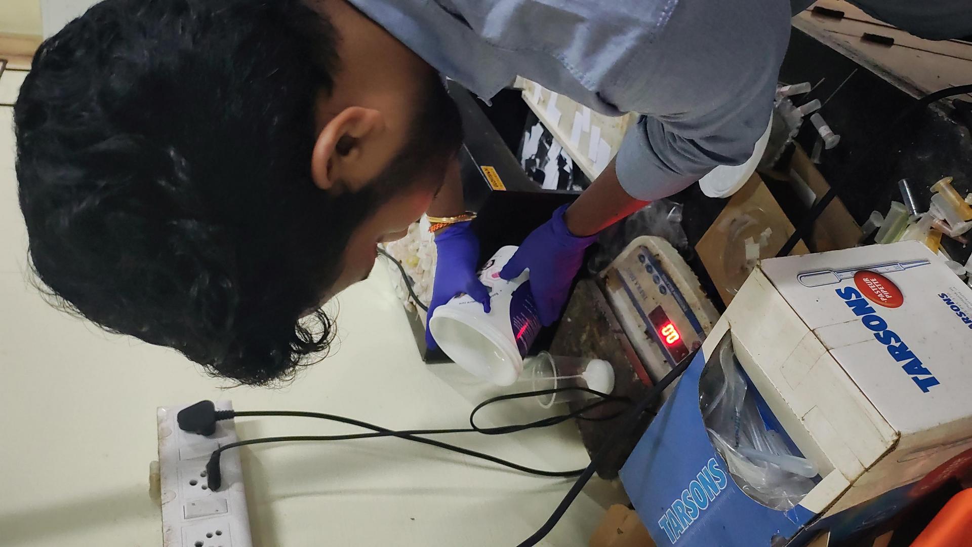
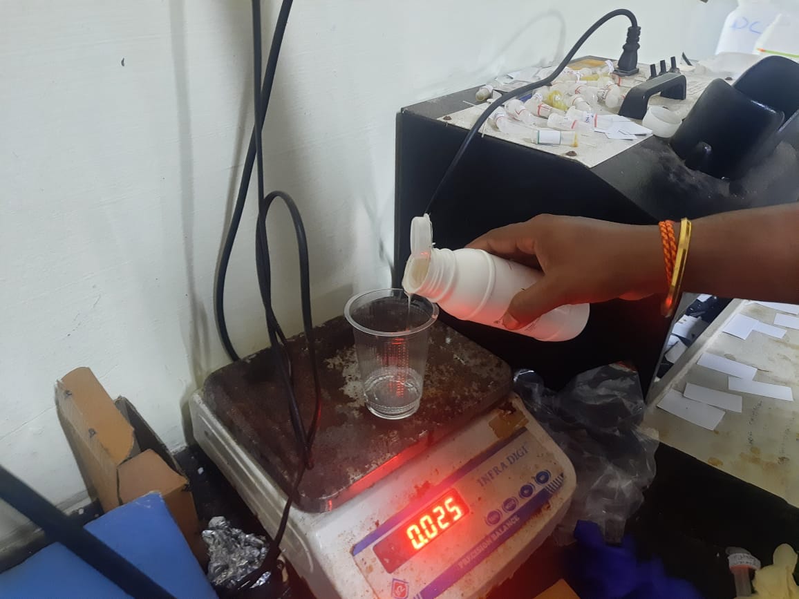
Then, I wore safety gloves to ensure proper handling and protection during the mixing process. I slowly poured the silicone base and catalyst into a plastic beaker
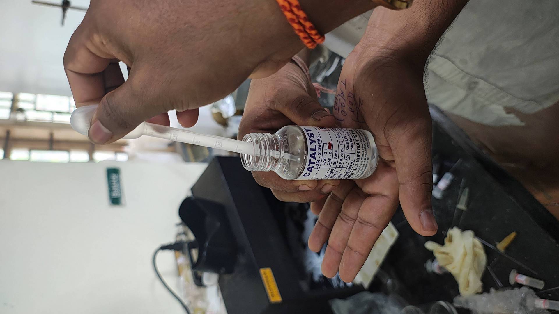
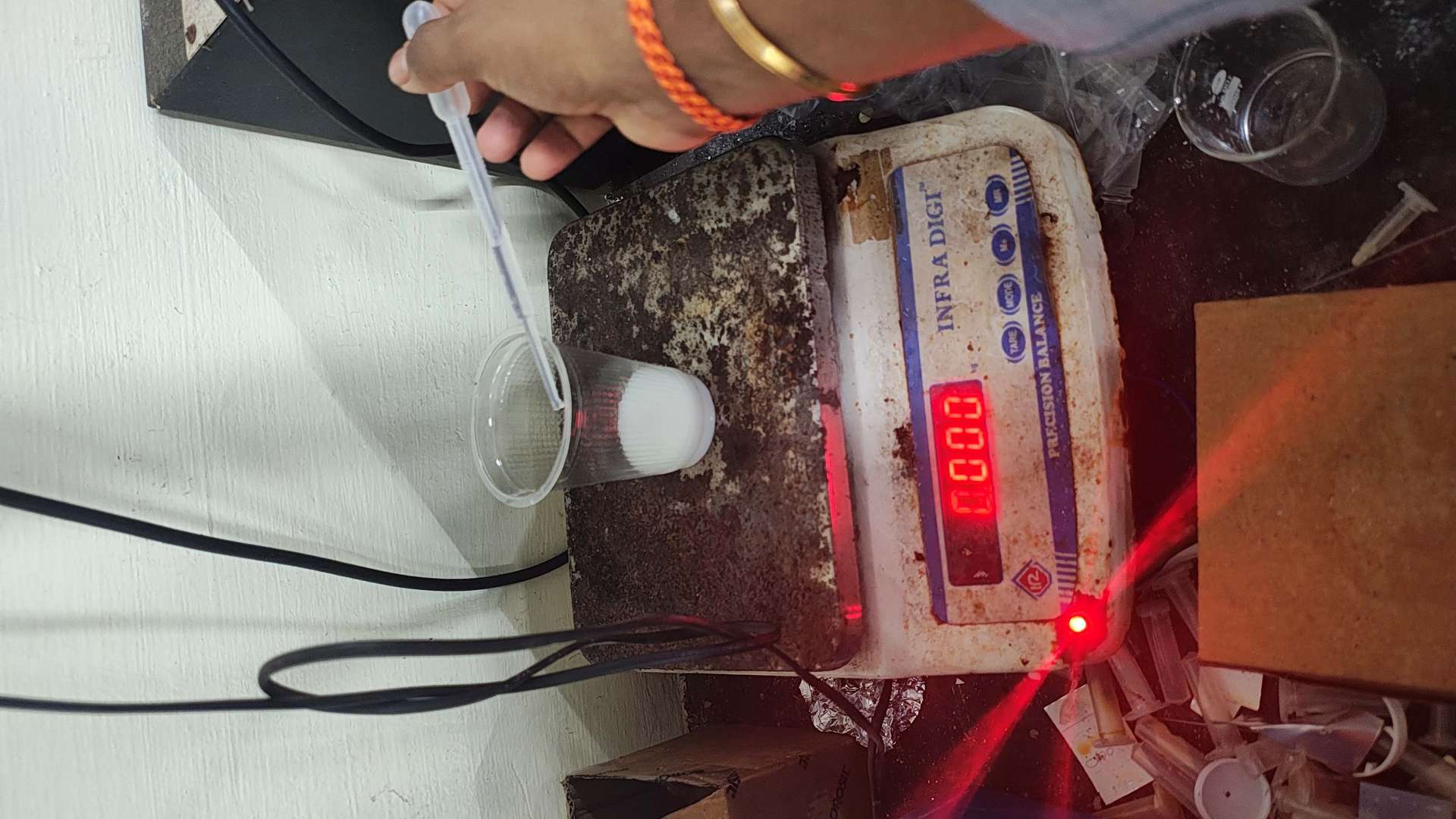
After pouring the silicone base, I tared the plastic beaker again to zero the scale, ensuring accurate measurement of the catalyst. I then added 2 grams of catalyst as per the required ratio. This precise measurement is crucial for proper curing and achieving a strong, detailed negative silicone mold.
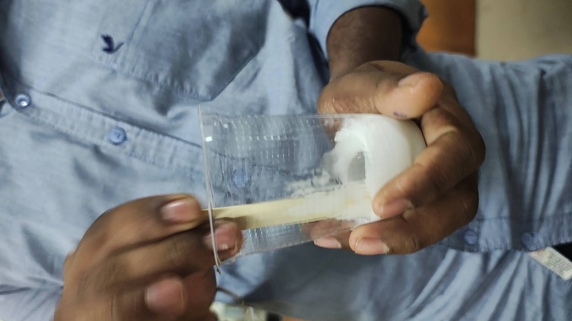
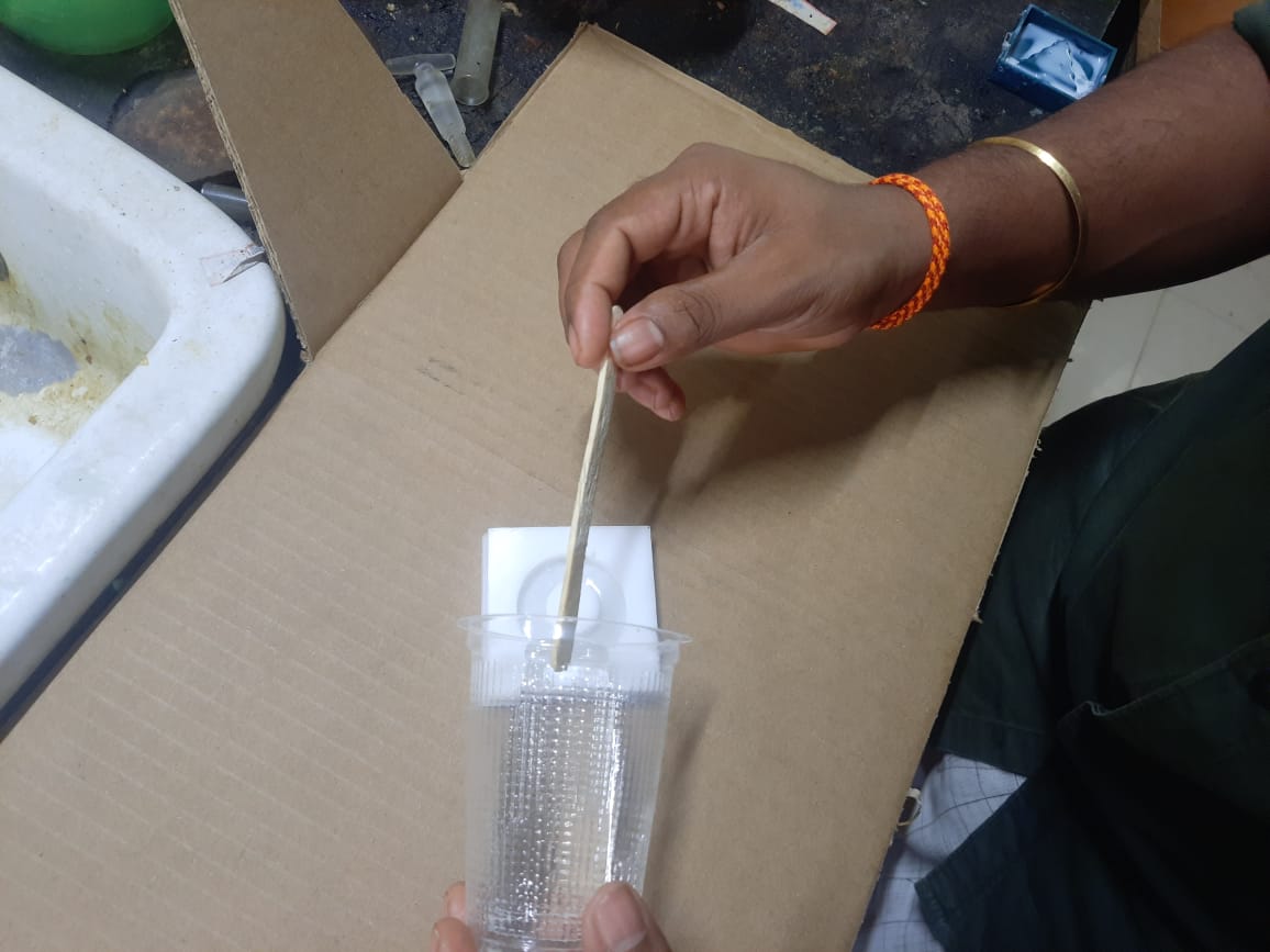
After adding the catalyst, I mixed the silicone thoroughly to ensure an even and consistent blend. This step is important to activate the curing process uniformly. I stirred slowly to minimize air bubbles and allowed the mixture to settle properly before pouring it into the mold,
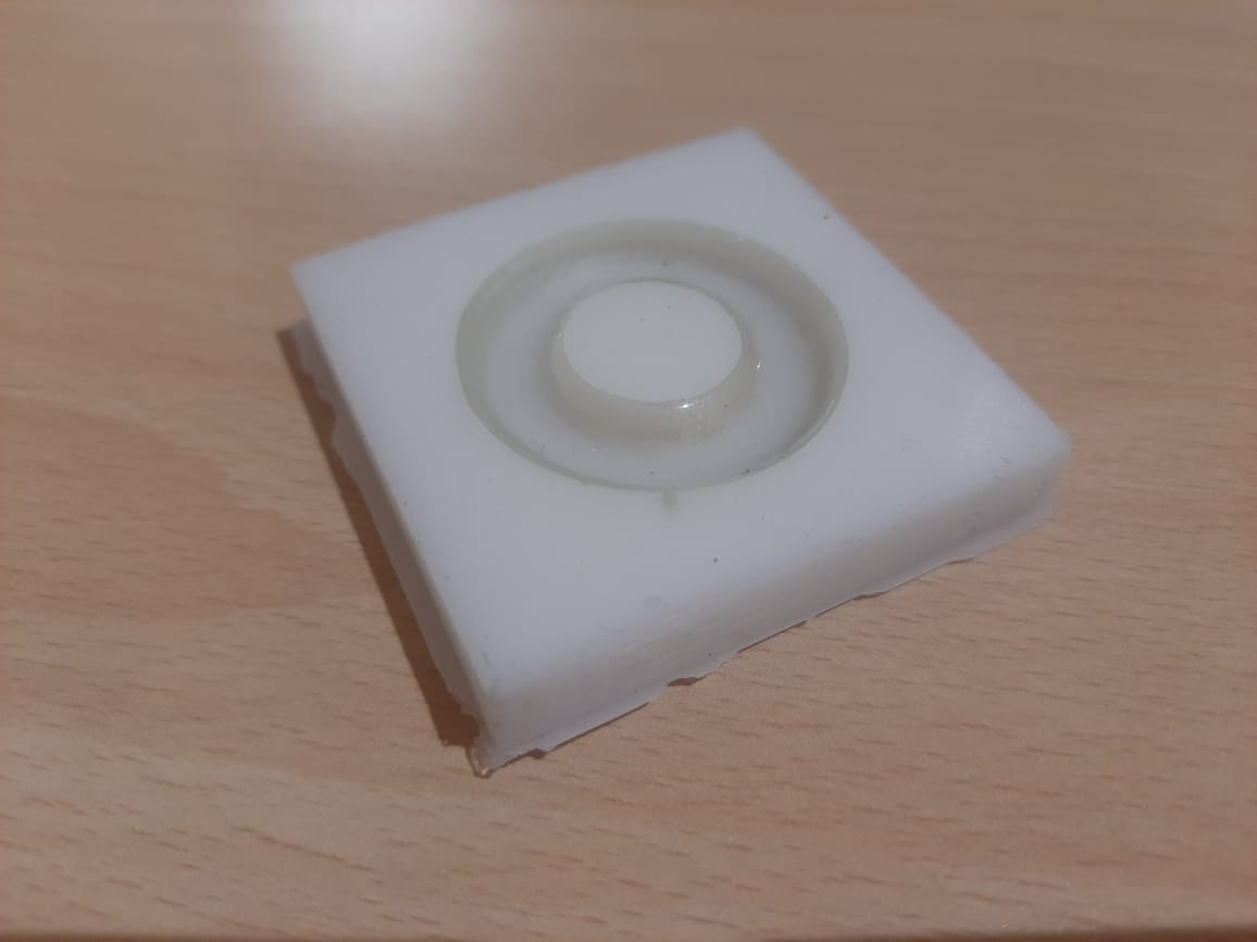
Then, I carefully poured the mixed silicone into the 3D printed mold cavity. I poured slowly from one side to allow the material to flow evenly and to help air bubbles escape naturally. i added releases agent before pouring mixed silicone This ensured the silicone filled all the fine details of the cavity
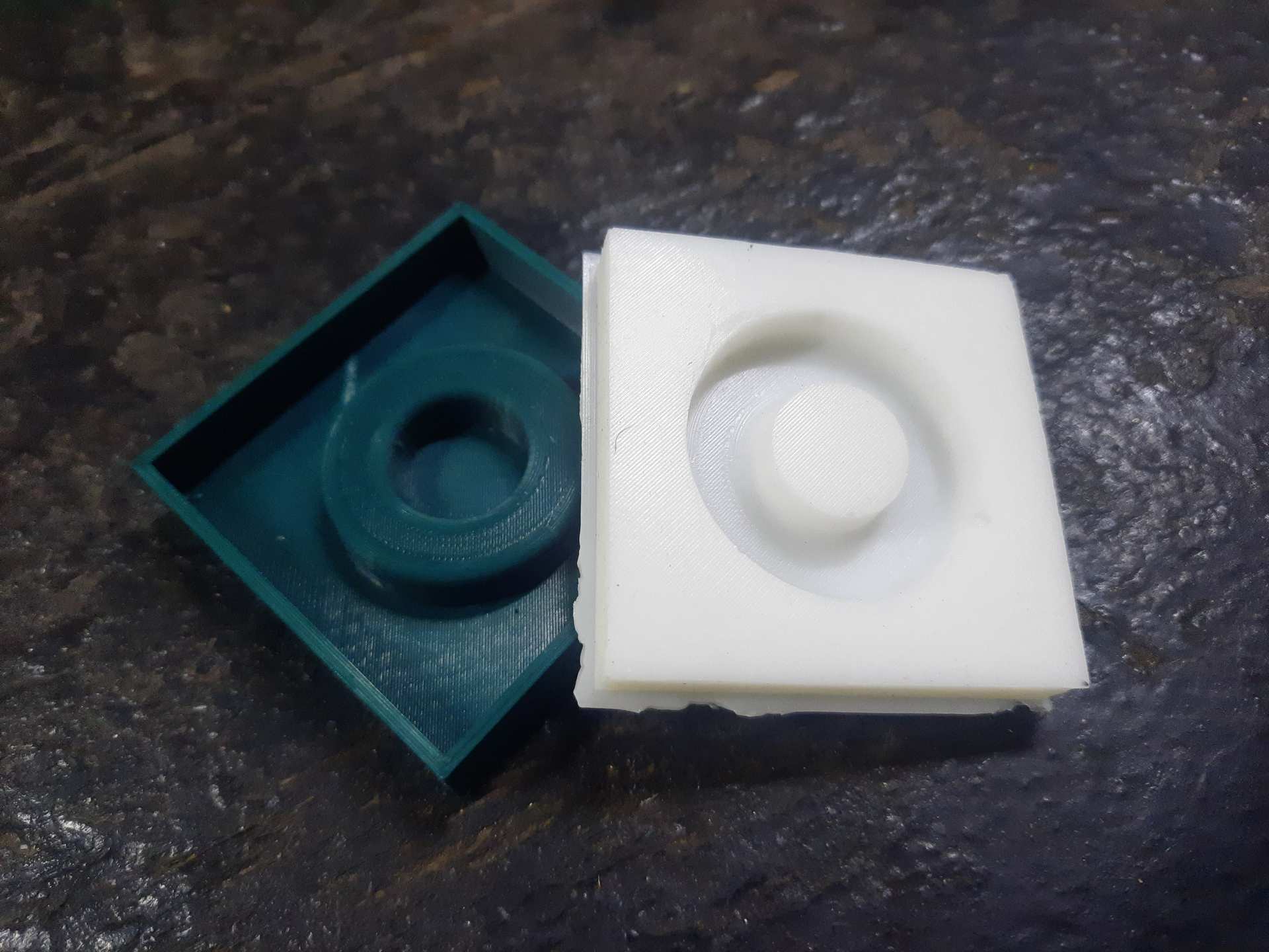
After the curing process was complete, the silicone mold set perfectly and looked clean and detailed. The surface was smooth, and all the features from the 3D printed mold were accurately captured. The final result was a high-quality negative mold, ready for chocolate or any casting material.
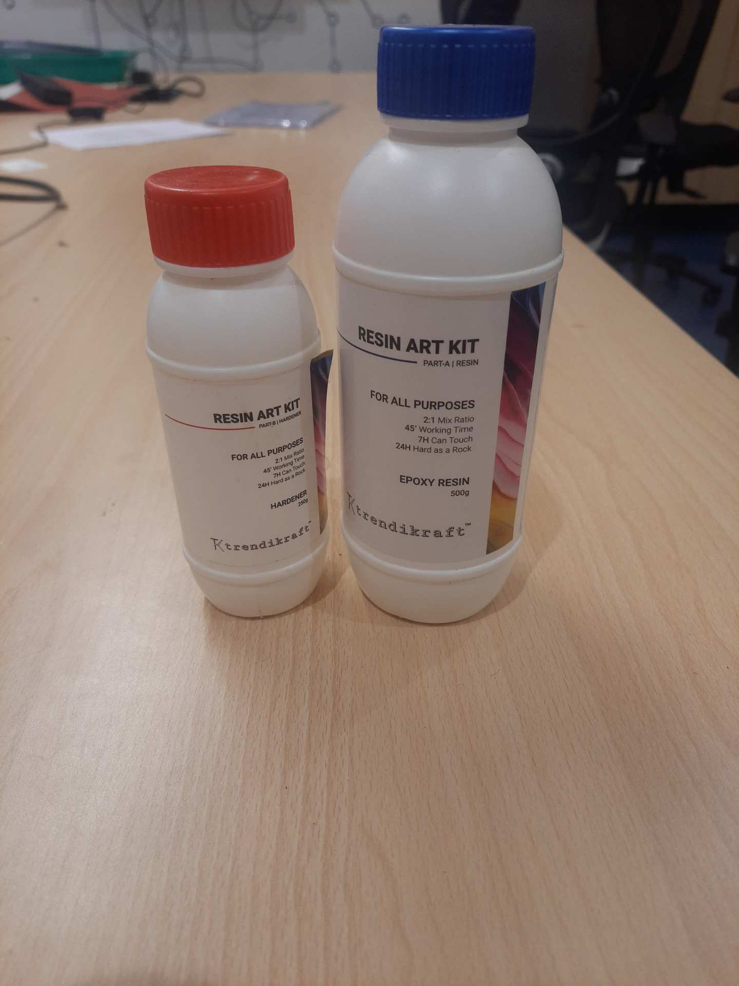
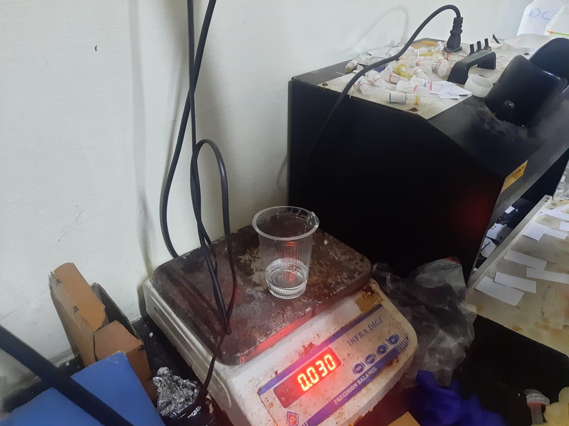
Again, I tared the 250 ml beaker before measuring the resin to ensure accurate weight. This allowed me to measure only the resin content, excluding the beaker’s weight. Accurate measurement is essential for proper mixing with the hardener
Then, I calculated the resin quantities based on the 2:1 mixing ratio (Part A: Resin, Part B: Hardener). After measuring the required amount of Part A (resin), I measured half that amount of Part B (hardener). This precise ratio is crucial to ensure proper curing, strength, and clarity of the final cast.
I added Part A (resin) in double the quantity compared to Part B (hardener), following the 2:1 mixing ratio. This ensures the correct chemical reaction for curing. Precise measurement is important to avoid incomplete curing or a sticky finish
After measuring Part A (resin), I added Part B (hardener) in the correct proportion—half the amount of Part A, following the 2:1 mixing ratio
Then, I slowly poured the mixed resin into the cured silicone mold, starting from one side to help the resin flow evenly and reduce air bubble formation. I ensured it filled all the details of the mold cavity properly.
Then, I allowed the resin to rest and cure undisturbed for the recommended time, giving it enough time to solidify completely. This step is crucial to ensure the final cast achieves full strength, clarity, and retains the exact shape
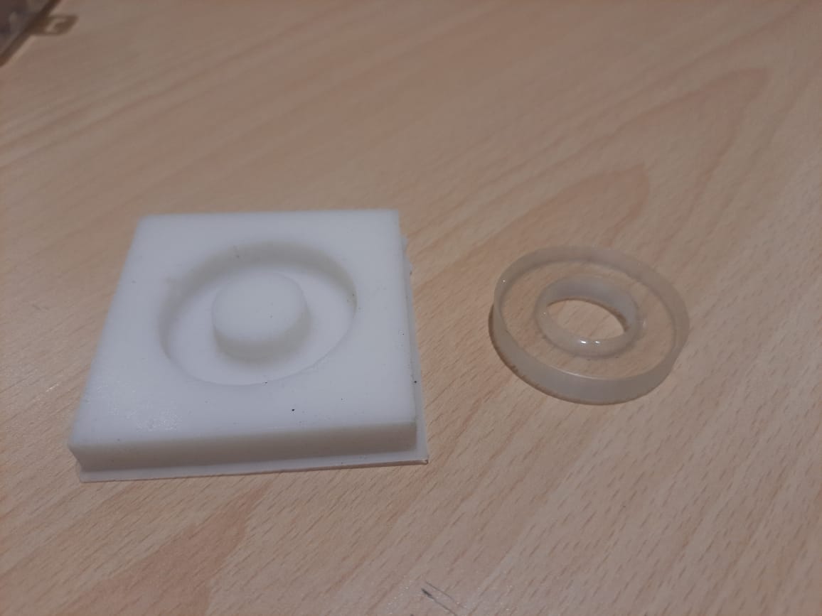
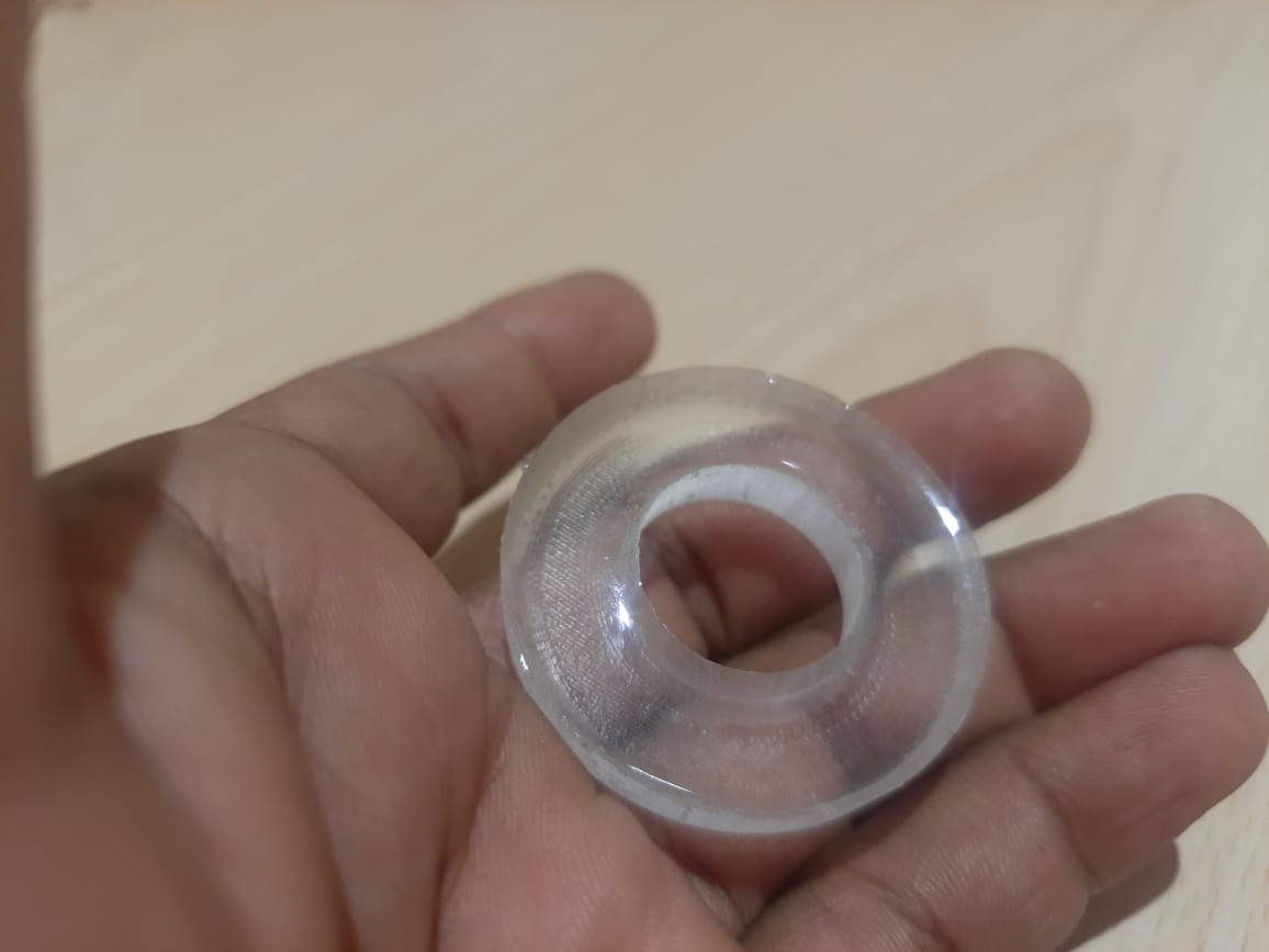
After the resin fully cured, I carefully separated it from the silicone mold. The casting came out very well, with smooth surfaces and clean details accurately captured from the mold. The final product was solid, well-formed, and reflected the quality of both the mold preparation and the casting process.