Group assignment
Individual assignments

Input devices are electronic components or sensors that allow a system—such as a computer or microcontroller—to receive data from the physical world. These devices detect physical changes (like motion, temperature, light, pressure, etc.) and convert them into electrical signals that can be processed, stored, or responded to by digital systems. In embedded systems and electronics projects, input devices play a critical role in making systems interactive and responsive. They help gather data from the environment or users, enabling automation and control.
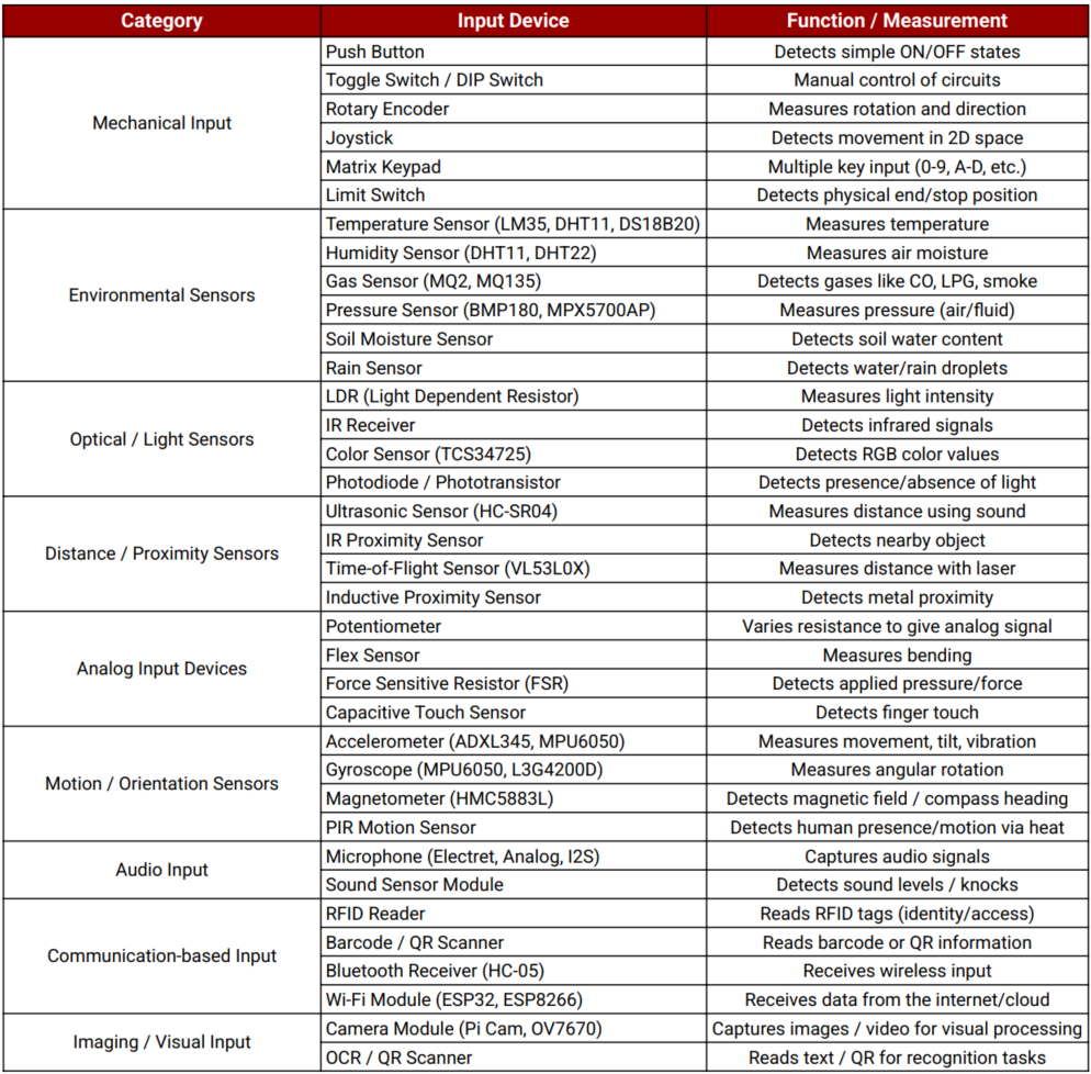
I arrived at this data with the help of ChatGPT, which guided me in organizing and understanding various input devices used in electronics. It assisted in structuring the information clearly and concisely in tabular form.
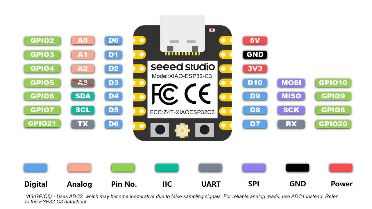
For input week, I used the ESP32-C3 module as the microcontroller because of its powerful features like built-in Wi-Fi, Bluetooth, multiple GPIO pins, and ADC support. It efficiently reads signals from input devices such as sensors, joysticks, and buttons, enabling real-time data processing and communication with other systems or displays.
Summary of ESP32-C3 Datasheet
The ESP32-C3 is a cost-effective, low-power, 32-bit RISC-V microcontroller with integrated Wi-Fi and Bluetooth LE 5.0. Designed for secure and efficient IoT applications, it provides robust wireless connectivity and flexible I/O configuration.
Technical Specifications
Microcontroller: 32-bit RISC-V Single-Core CPU
Clock Speed: Up to 160 MHz
SRAM: 400 KB
ROM: 384 KB
Flash: External (typically 4 MB via SPI)
EEPROM: Not available (can be emulated using flash)
Operating Voltage: 3.0V to 3.6V
Input Voltage (recommended): Via 3.3V regulated supply
Wi-Fi: IEEE 802.11 b/g/n (2.4 GHz, up to 150 Mbps)
Bluetooth: Bluetooth 5.0 LE with Mesh and Long Range
Digital I/O Pins: 22 GPIOs
ADC: 12-bit, up to 6 channels
UART: 2
SPI: 2
I2C: 1
PWM: Available on all GPIOs
Timers: Multiple hardware timers
USB: USB 2.0 Full-Speed (native support)
Security: AES, SHA, RSA, ECC, Flash Encryption, Secure Boot
Power Consumption: Active Mode ~130 mA, Light Sleep ~0.8 mA, Deep Sleep ~5 µA
Package: QFN32 (5 mm × 5 mm)
Supported Tools: ESP-IDF, Arduino IDE, PlatformIO, MicroPython
ESP32-C3 Pin Details
The ESP32-C3 supports flexible pin assignment using its GPIO matrix, allowing peripherals to be remapped to available pins as needed.
Digital I/O Pins (GPIO0 to GPIO21)
All GPIOs are multifunctional and support input, output, pull-up/down, PWM, and peripheral mapping. Maximum current draw per GPIO is approximately 20–40 mA depending on usage.
Important GPIOs
GPIO0 – Used for boot mode selection during flashing
GPIO1 and GPIO3 – Default UART TX and RX (avoid using when Serial Monitor is active)
GPIO9 and GPIO10 – Usually connected to internal flash, should not be used for I/O
GPIO19 and GPIO20 – USB D- and D+ on some modules
Analog Input Pins (ADC1 Channels)
ESP32-C3 has 6 ADC1 channels with 12-bit resolution, mapped to GPIOs like GPIO0 to GPIO5. These are used for reading analog voltages from 0 to 3.3V.
Power Pins
3V3 – Regulated 3.3V power input
GND – Ground reference
EN – Chip enable (reset if pulled low)
VBUS – USB power input (5V on USB)
LDO Cap – Capacitor pin for internal LDO regulator (used in specific modules)
Communication Pins
Serial (UART):
Default UART uses GPIO1 (TX) and GPIO3 (RX). UARTs can be remapped to other pins using software.
SPI:
SPI0 is reserved for internal flash. SPI1 is available for general-purpose communication and can be mapped to any free GPIOs.
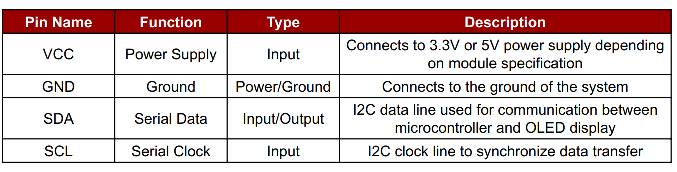
I2C:
Supports one I2C controller in master/slave mode. SDA and SCL lines can be assigned to most GPIOs. Common assignments are GPIO4 (SDA) and GPIO5 (SCL).
USB:
Native USB 2.0 interface supported on modules like ESP32-C3-DevKit. D+ and D- are usually mapped to GPIO19 and GPIO20.
Security Features
Hardware-based Flash Encryption
Secure Boot (version 2)
Cryptographic acceleration for AES-128/256, SHA-2, RSA-3072, and ECC
Digital Signature Peripheral
Summary
Digital Pins (GPIO0–GPIO21): General-purpose I/O with PWM and peripheral mapping
Analog Pins: 6 channels of 12-bit ADC
Power Pins: 3.3V input, multiple GND, EN, USB VBUS
Communication Interfaces: UART, SPI, I2C, USB
Connectivity: Integrated Wi-Fi (2.4 GHz) and Bluetooth 5.0 LE
Security: Supports advanced encryption, secure boot, and digital signature
Power Modes: Active (~130 mA), Light Sleep (~0.8 mA), Deep Sleep (~5 µA)
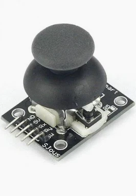
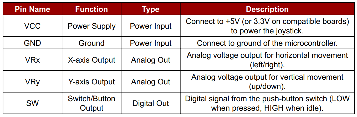
A Joystick Module Sensor is an input device used in electronics to detect motion or direction in two axes – typically X-axis (left/right) and Y-axis (up/down) – and sometimes includes a Z-axis button press (when the joystick is pushed down). It works similarly to the analog stick found in game controllers.
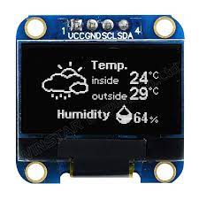
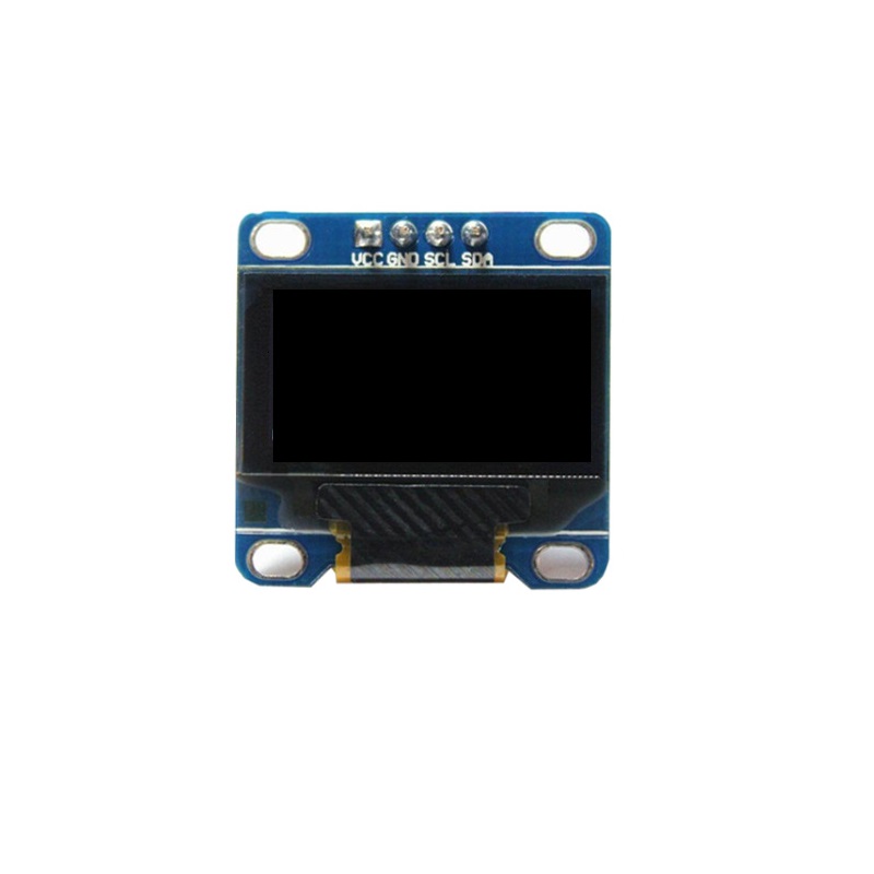
OLED Display Module Blue color data sheet
An OLED (Organic Light Emitting Diode) Display Module is a self-emissive display that uses organic compounds to emit light when current flows through them. These displays are popular in embedded systems and electronics projects due to their lightweight, low power consumption, and high contrast visibility, even in dark environments.
Adafruit SSD1306 Library - GitHub
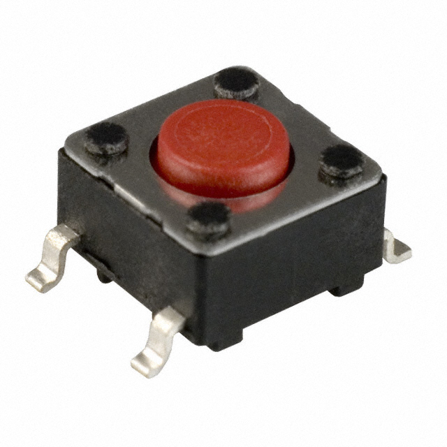
A push button is a simple switch mechanism used to control processes in electronic devices. When pressed, it completes an electrical circuit, allowing current to flow; when released, the circuit breaks.
In this project, I used the push button for an ON/OFF control purpose, toggling device states efficiently.
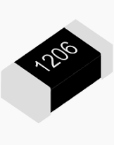
A resistor is a passive electronic component that limits or regulates the flow of electric current in a circuit. It provides resistance, measured in ohms (Ω), and helps control voltage and current to other components. In my project, resistors were used to protect components like LEDs and ensure stable operation.
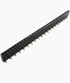
Female header pins are connectors used to make reliable and detachable connections between electronic components or modules. They consist of a row of sockets that accept male pins, allowing easy interfacing between boards, sensors, or microcontrollers. In my project, I used female header pins to connect sensors and modules to the ESP32-C3 microcontroller without soldering them directly. This helps in easy testing, replacement, and modular design.
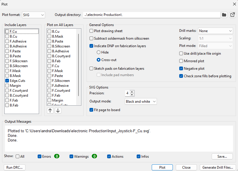
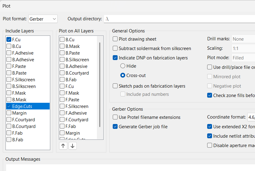
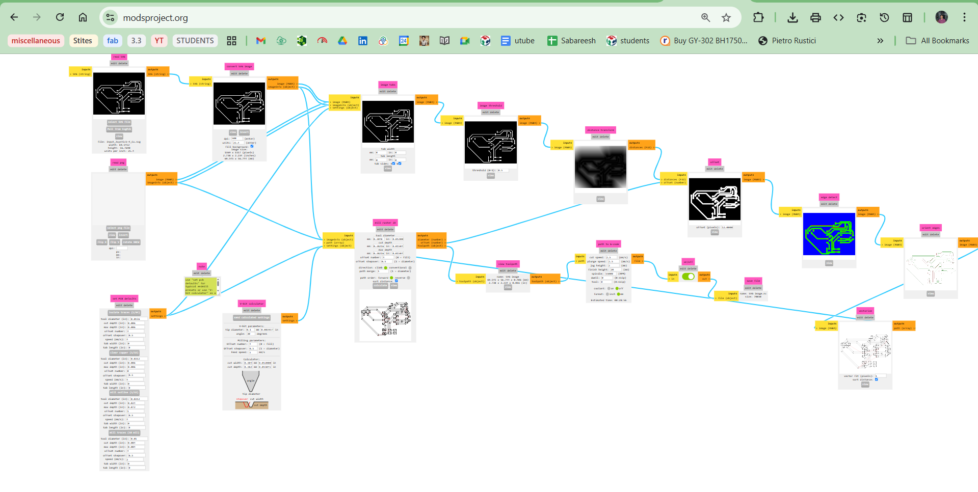
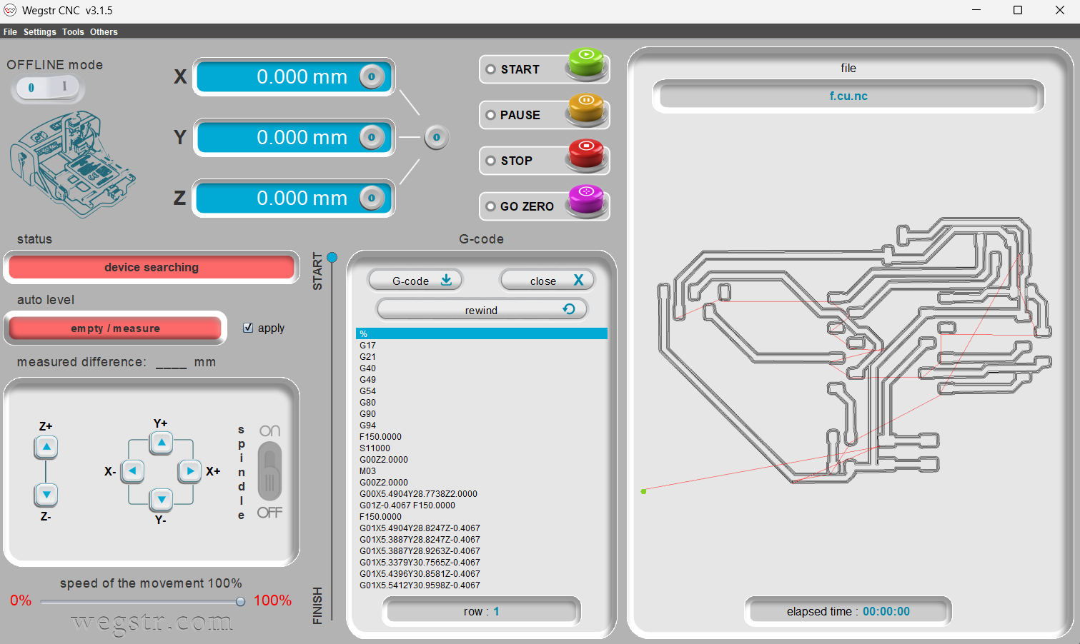
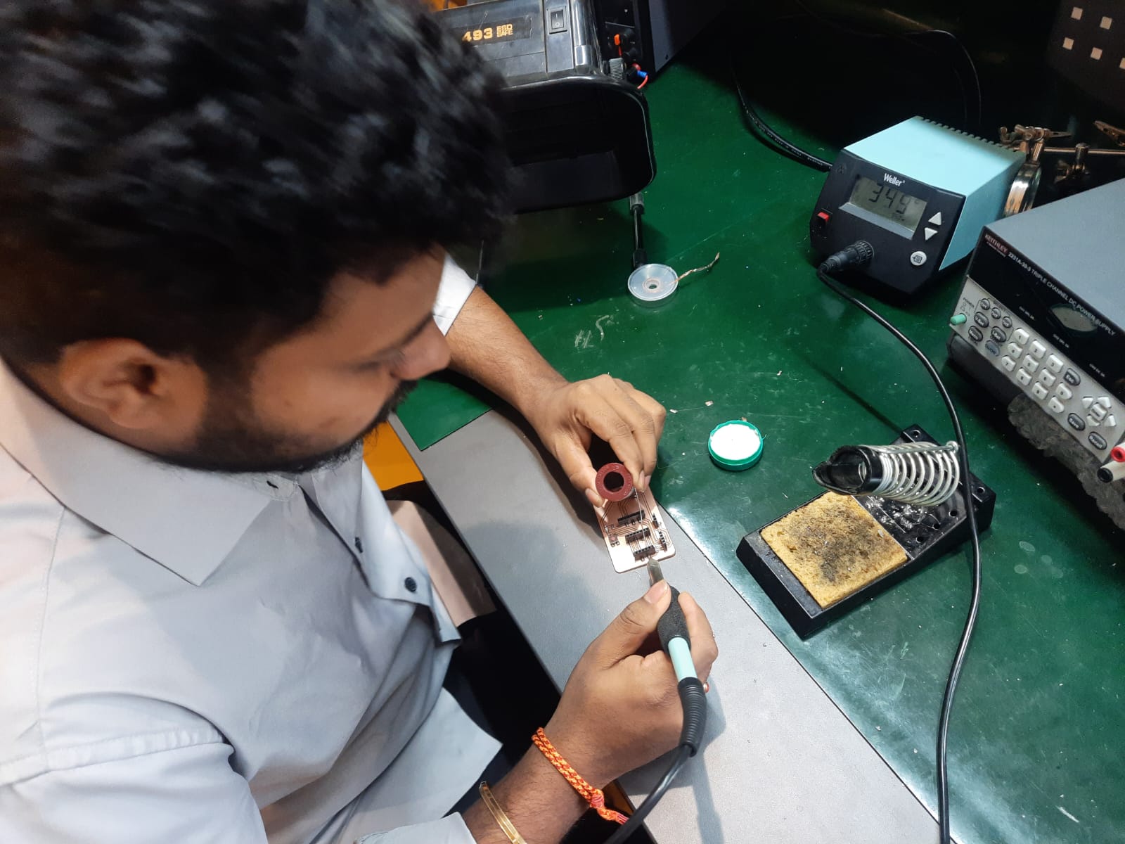
If you're not familiar with these steps, kindly visit my Electronics Production page where you’ll find detailed explanations. I followed the same steps here as well, so no worries.
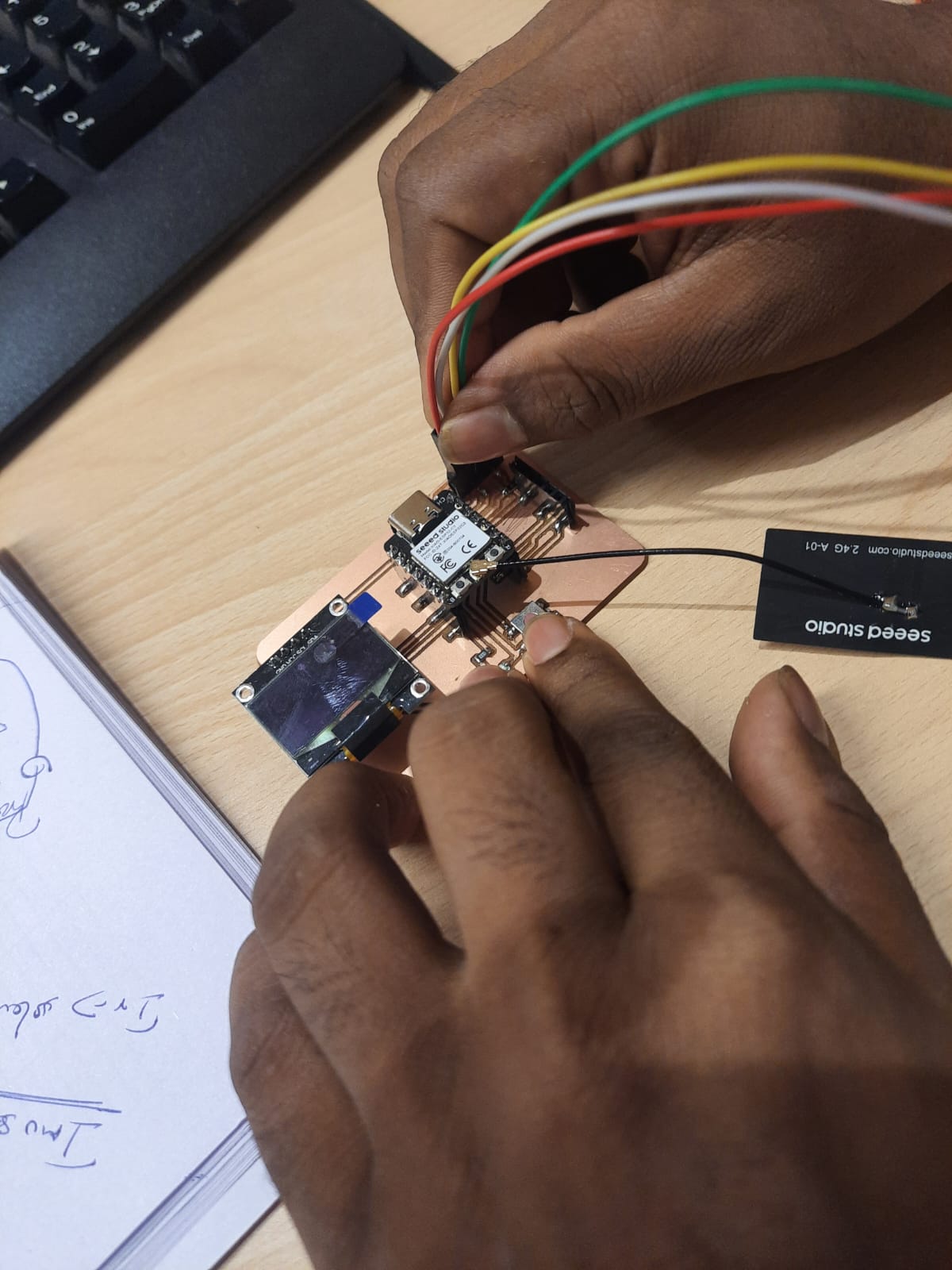
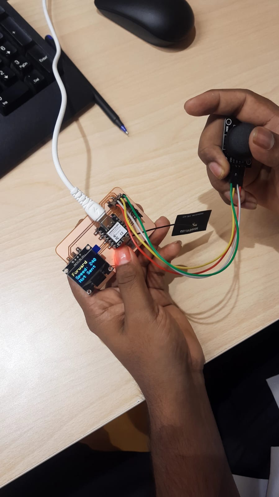
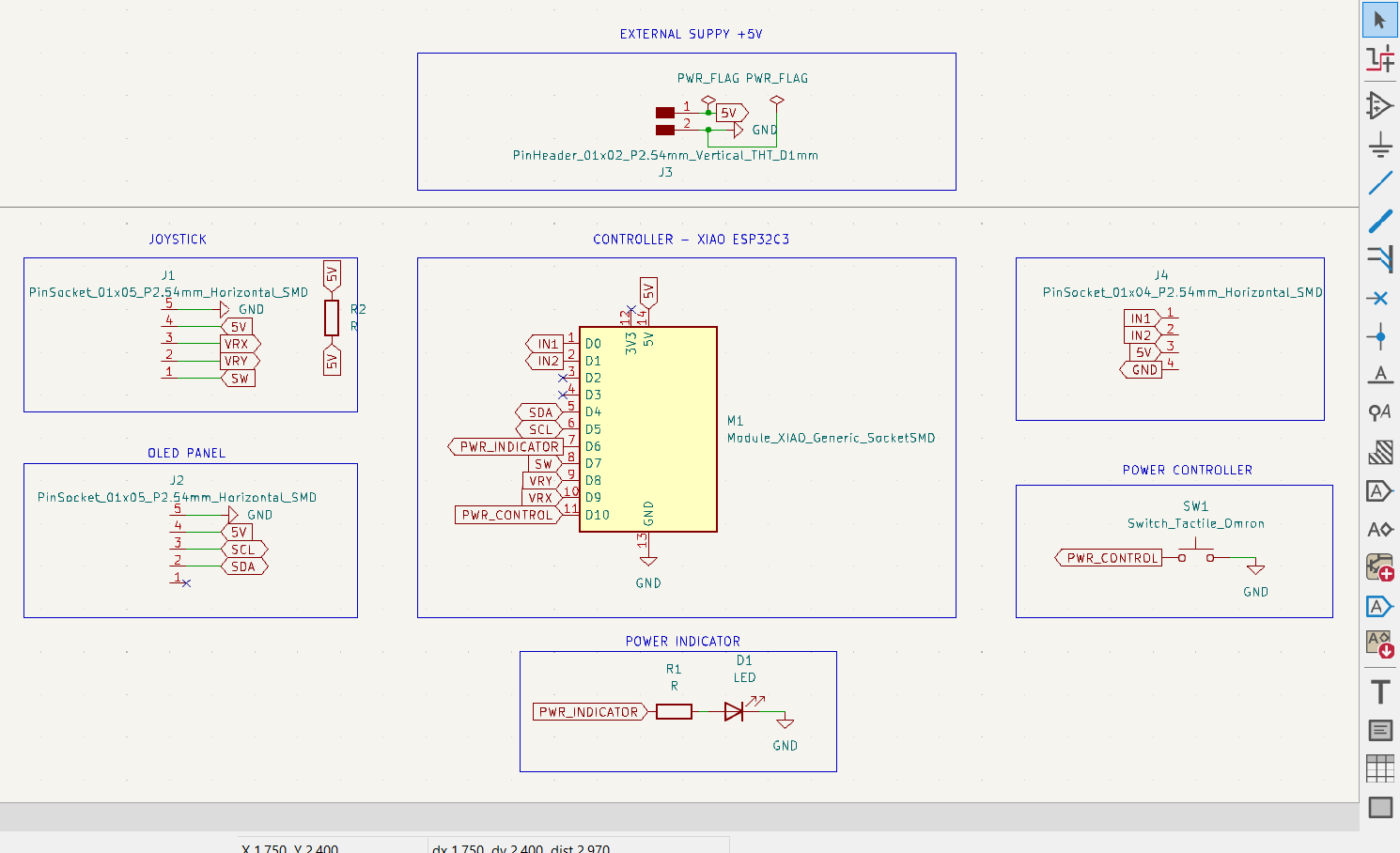
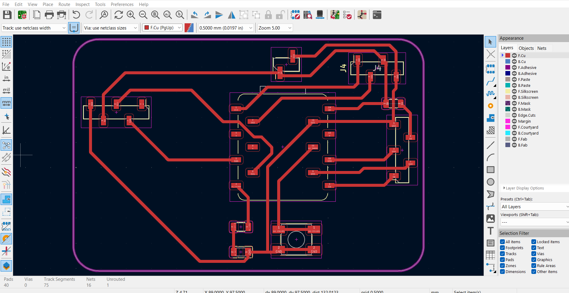
This week, I concentrated on developing the input processing component for my final project. I designed and implemented a joystick controller to interface with my bot. This allows me to manually control its movement and test responsiveness, helping refine both the hardware and software aspects of my robot's navigation system.