Core Concepts of 2D Plotter
To understand the core concepts of a 2D plotter, I explored multiple YouTube videos. These resources helped me grasp how stepper motors, belts, pulleys, and firmware work together to enable precise X and Y axis movements. Watching real-world builds and tutorials clarified the mechanical and electronic integration needed to create a functional plotter.
Frame Size
I discussed with my team and we collectively decided on an overall frame size of 30 cm x 30 cm for the 2D plotter. This compact dimension offers a balance between portability and a sufficient working area for plotting tasks. The square frame also simplifies symmetry, axis alignment, and machine calibration.
Garb CAD Intro
GrabCAD is an online platform that offers a large library of free CAD models, mainly in STEP and STL formats. Engineers and designers use it to share, download, and collaborate on 3D designs. It helps speed up product development and ensures component accuracy during digital prototyping and assembly planning.
Link to Grab CAD
For my 2D plotter project, I sourced essential STEP files from the GrabCAD website to accurately model and assemble the machine in CAD. These components included the NEMA 17 stepper motor, Arduino Uno, CNC shield, SG90 servo motor, GT2 pulleys, rollers, and standard nuts and bolts. Utilizing these detailed 3D models ensured precise alignment and integration of both mechanical and electronic parts, facilitating a smoother design and assembly process.
Design Assembled In Fusion 360
In Fusion 360, my teammate Charath and I assembled the entire 2D plotter. Each step of the process has been documented in our group assignment. Kindly check the group assignment page for detailed visuals and explanations
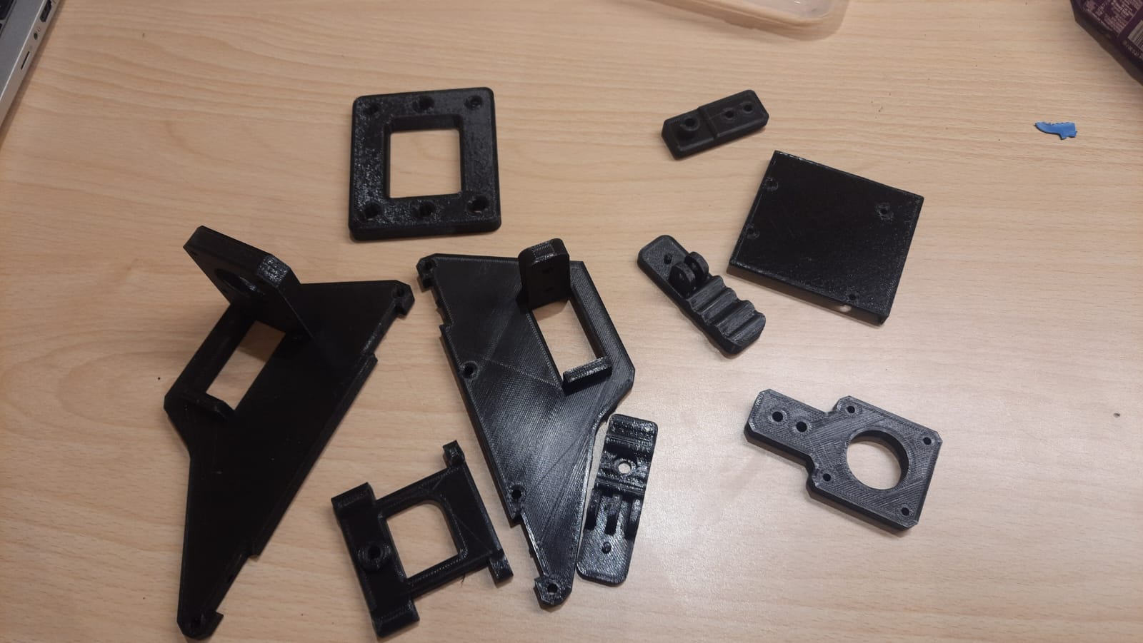
For Machine Week, I designed custom 3D parts required for the machine’s structure and functionality. This included mounts, brackets, casing elements, and any mechanical supports needed for the motion system. In the design files, I included all 3D models with accurate dimensions, alignment features, and holes for assembly. These were saved in standard formats like STL and STEP, ensuring compatibility with 3D printing and CNC processes. All original design files are organized and included for documentation and future reference.
Original Files
3D Printed
Then, my teammates and I 3D printed all the necessary components using a FlashForge 3D printer. We chose black PLA material for its strength and ease of printing. These custom parts were essential for assembling the 2D plotter accurately and ensuring the mechanical components fit together properly during final construction.
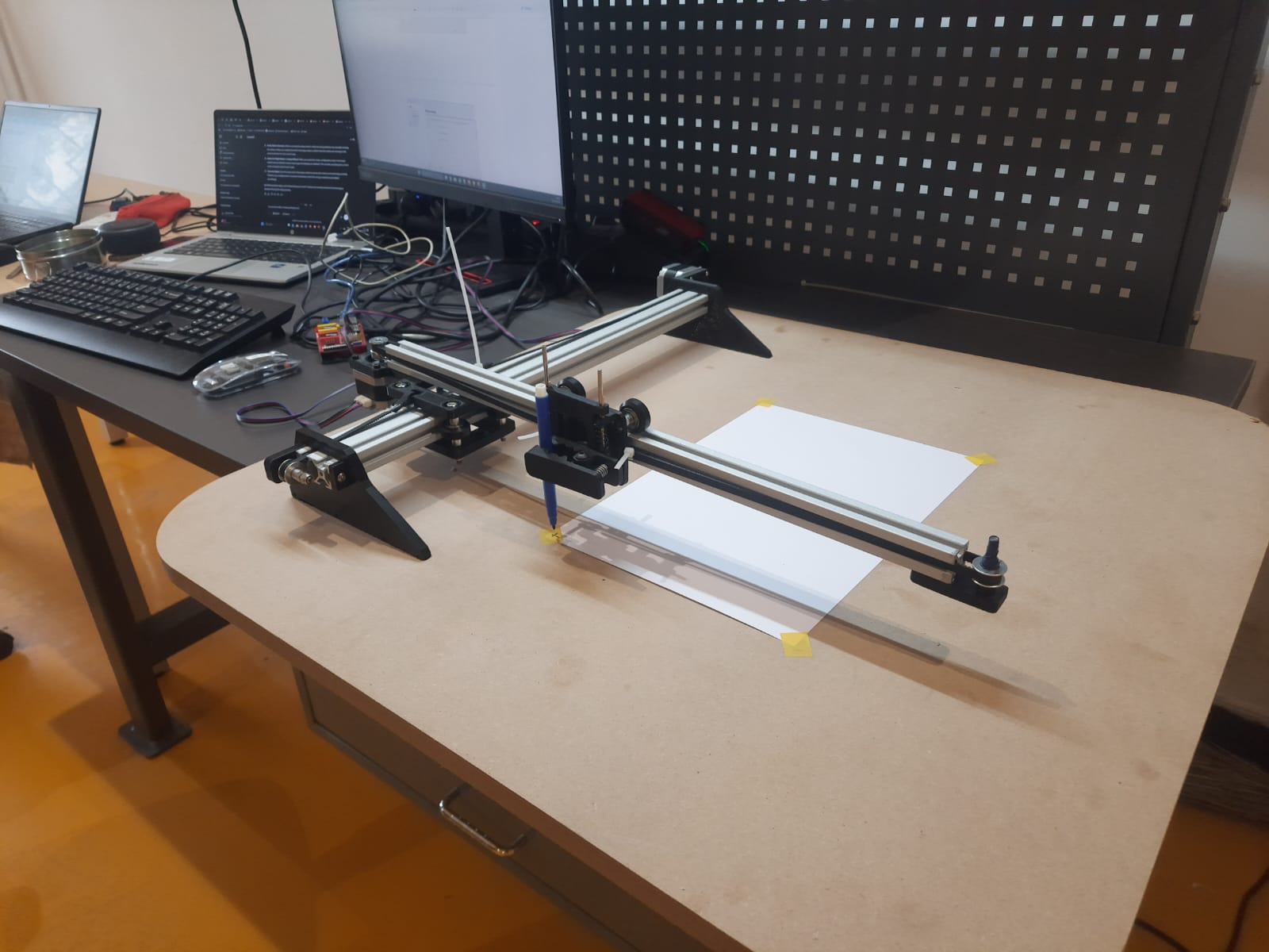
Hardware Assembly
We assembled the 3D printed parts using nuts, bolts, belts, and glue. Nuts and bolts provided strong mechanical joints, while belts helped in transferring motion smoothly between axes. Glue was used selectively for parts that needed extra support or where screws couldn't be used, ensuring overall stability and functionality of the machine.
Analyse and Solve Technical Problems
Improving Timing Belt Tension: From Zip Ties to Stapler Pin Fixation
- Understanding the importance of proper belt tension and secure fastening, I analyzed alternative methods to improve the setup without causing damage to components.
- Instead of zip ties, we used stapler pins to fasten the belt securely onto the frame, which provided a much stronger hold and prevented slippage.
- After securing the belt with stapler pins, the tension improved significantly, which stabilized the X-axis movement and eliminated the wobble in the Z-axis.
- This solution enhanced the overall precision and reliability of the plotter during operation.
- Through this process, I learned the critical importance of mechanical stability and proper fastening methods in motion control systems.
Z-Axis Deviation Due to Single X-Axis Support in 2D Plotter
- During the initial testing phase of the 2D plotter, I observed a deviation or wobble in the Z-axis movement, which affected the accuracy of the plotting.
- This issue arose because the design utilized a single X-axis support, which did not provide sufficient stability at the end part of the axis, causing mechanical flex or misalignment.
- To secure the timing belt responsible for X-axis movement, we first tried using zip ties, as proper clamps were not available at the moment.
- However, the zip ties failed to hold the belt firmly, resulting in slack and improper tension, which led to inconsistent motion and reduced precision.
Identifying and Implementing Design Improvements for Enhanced Plotter Performance
Upgrade from Single X-Axis to Dual Support System
The deviation at the end of the X-axis revealed structural instability. Adding a second support rail or linear guide can improve Z-axis consistency and plotting accuracy.
Design Proper Belt Clamping Mechanisms
The initial use of zip ties failed to maintain belt tension. Designing dedicated 3D-printed belt clamps or using standard belt anchors can enhance mechanical reliability.
Strengthen Frame Rigidity
Minor shifts in plotter structure under load suggest the need for a more rigid frame material or reinforcement design (e.g., corner brackets or thicker profiles).
Include Adjustable Tension System
Instead of manually fixing with pins or glue, integrate an adjustable tensioner in the belt path for easy tuning and maintenance.