
Machine Design
Here's a summary about what you'll see next:
- 1) Brief about the machine
- 2) Group Assignment
- 3) Individual Assignment
-
- X-Axis Design - Fusion 360
- X-Axis Fabricate - Table Saw & Laser-Cut & 3D Print
- X-Axis Assembly
- Stepper Motor Test
- Code Spiral Development
- Soil Moisture Sensor Test
- Water Pumps Test
- Water Tank Holder Design
- Cable Management and Final Wiring
- 3) Original Files
1) Brief about the machine
This week we needed to design a machine that included mechanism + actuation + automation + application. After lots of thinking and searching we saw an interesting project which is Farm Bot. It's a CNC farming machine that helps grow food and plants for everyone and maintain low consumption of water. So we decided to make it on a small scale. The main features of this machine will be that it can read the soil moisture level in different pots or spots we define and it says which plant needs to be irrigated and activate irrigation for it.
The machine will have UART communication as each axis will have its own microcontroller (Arduino Uno) and there will be a master microcontroller (Xiao ESP32-C3) controlling them via web interface.
Our machine will be moving in 3 axis and the z axis has 2 end effectors which are the soil moisture sensor and the water pump. Each axis has its own limit switch.
Next, we will see how we managed to work on this machine as a team and brought the machine out to the world.
2) Group Assignment
To get this machine done we agreed that each one of us will work on an axis from beginning to the end. Amr will work on the Y-Axis, I will work on the X-Axis, and Eman will work on the Z-Axis. Then we will integrate all our designs together.
This way made a great collaborative team as we needed to communicate together to know how we will integrate each axis with the other based on our designs and in the same time no one is falling behind or delaying the others.
This also helped as if someone finished his design and moved to the next step for example coding. He made it easier for the rest of the team to build on what he already started and not starting from the beginning. In our case this person was Amr :D. We depended on him a lot in the code.
So let's get started with the journey of making the X-Axis and lots of cool stuff.
3) Individual Assignment
1. X-Axis Design - Fusion 360
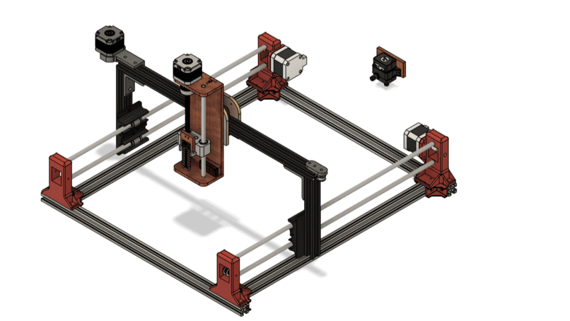
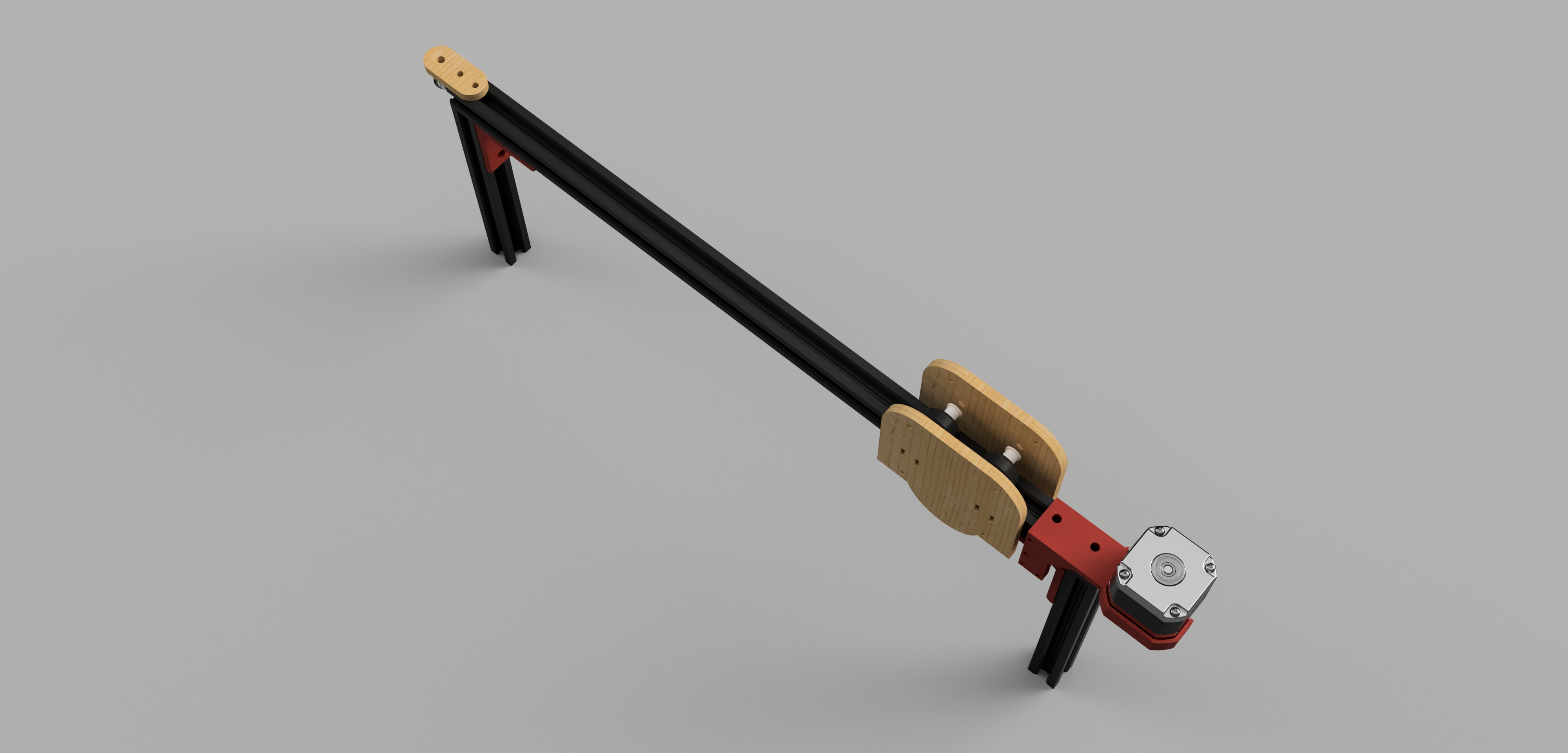
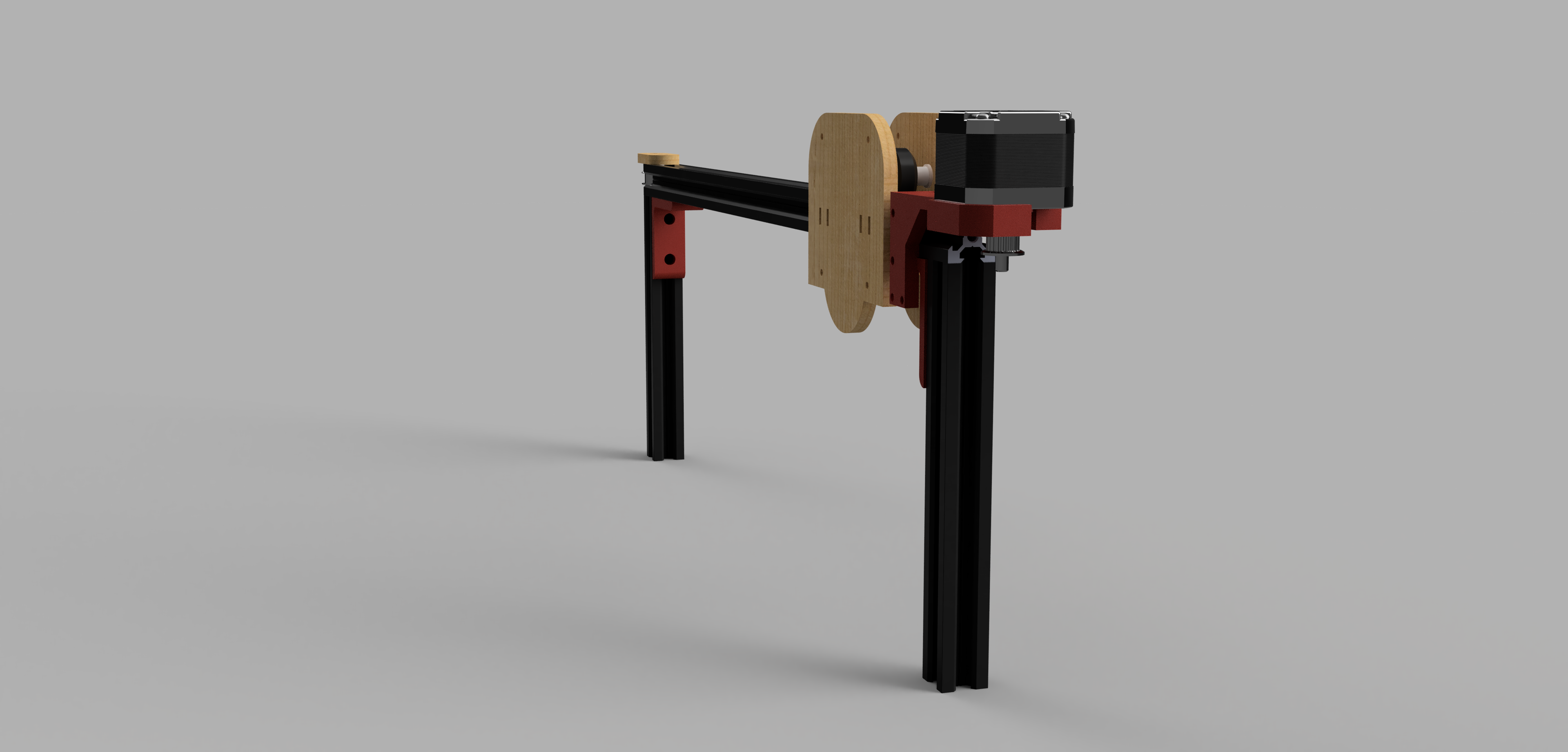
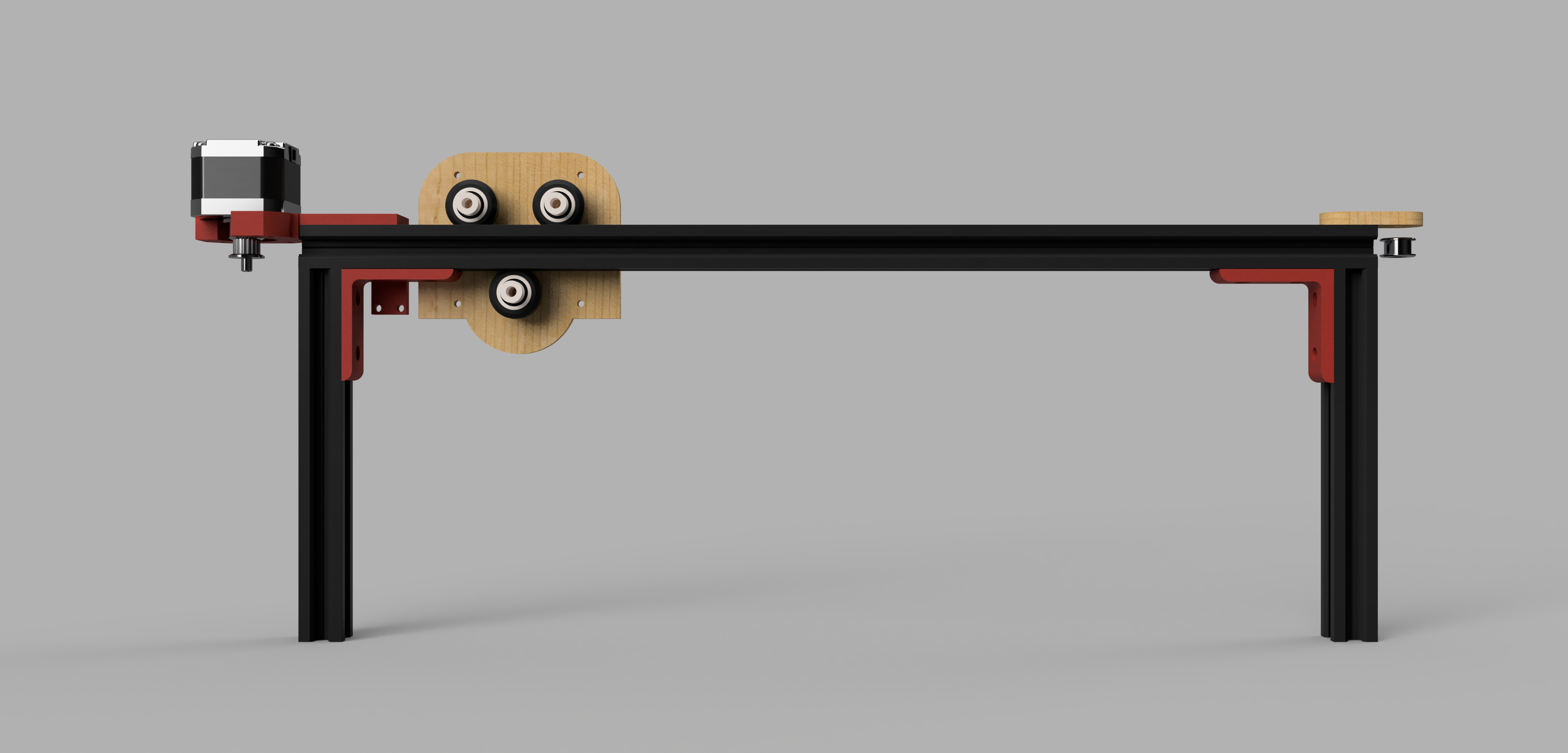
The first thing to do for me was to design the X-Axis. There are lots of ways to build an axis and make it move but I was interested in building it with Aluminium profiles and the movement using a belt.
We checked the inventory and found that we had 20x20mm aluminium profiles and all other needed components. I searched for this profile on mcmaster but I couldn't find it so I downloaded a 3D design of Creality Ender 3 Extended Travel and it helped me a lot with the components in the design.
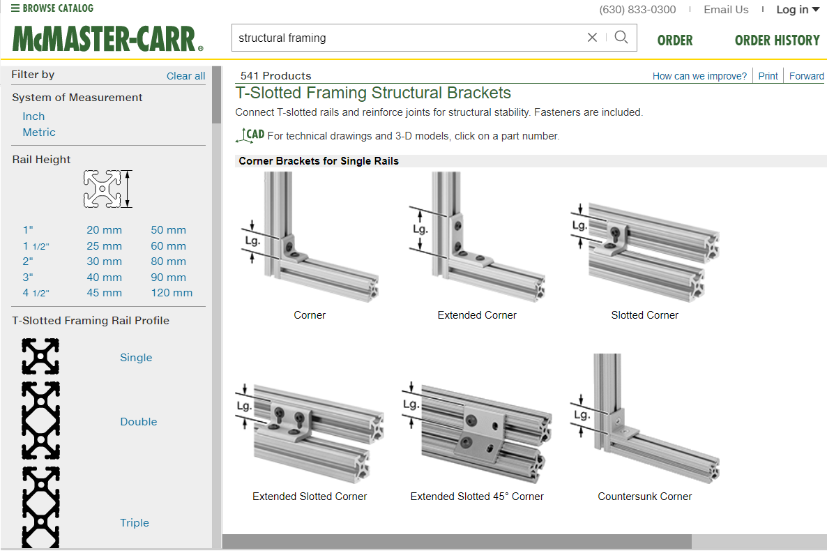
I first added the profiles and then searched on mcmaster for corners for the framing and chose the extended corner because I'll not be having any other corner to joint the profiles together from so I needed the corner to have 2 screws on each side to hold the profiles together without moving around.
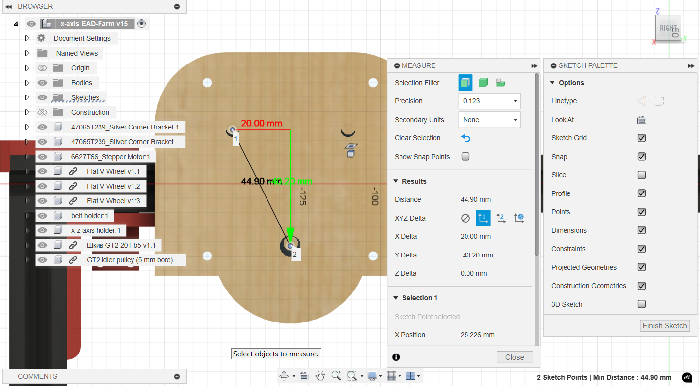
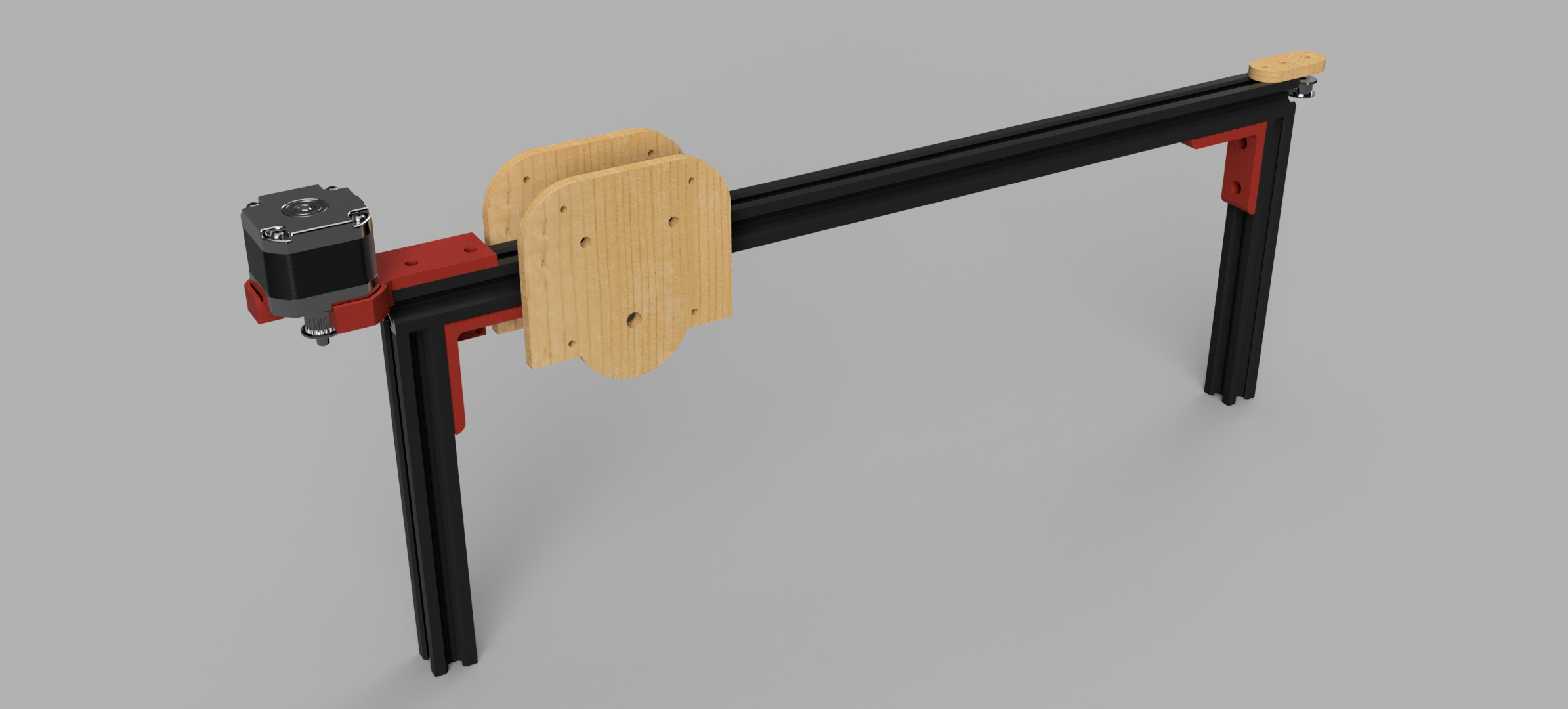
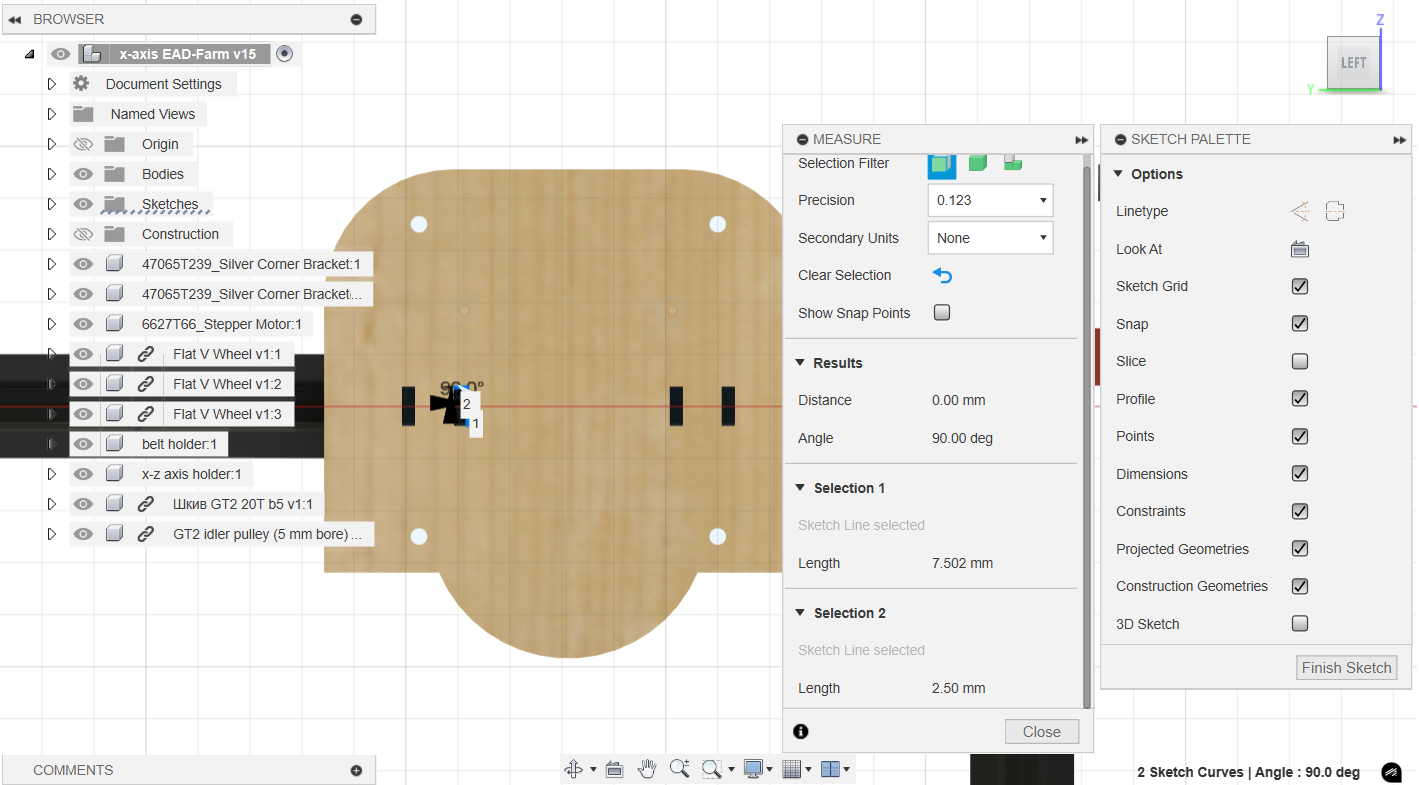
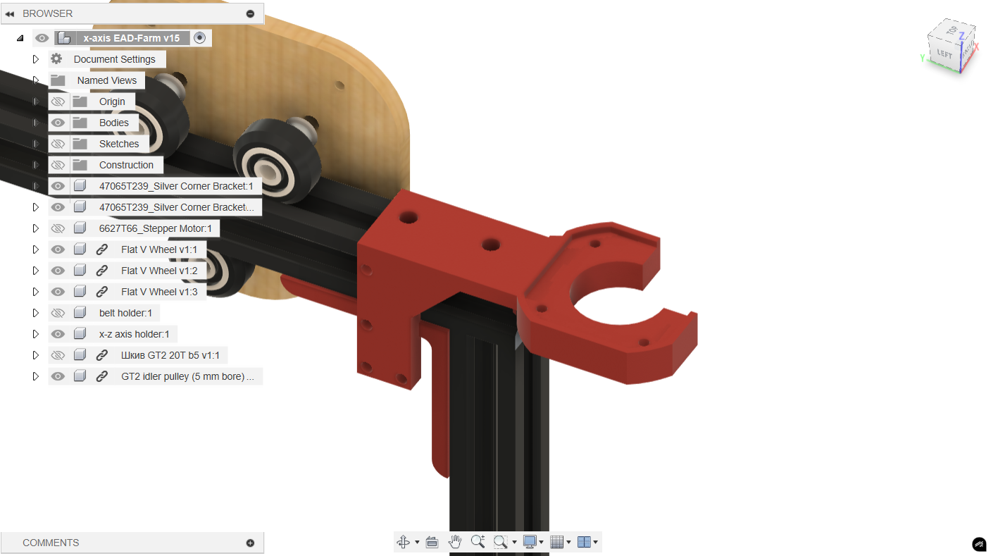
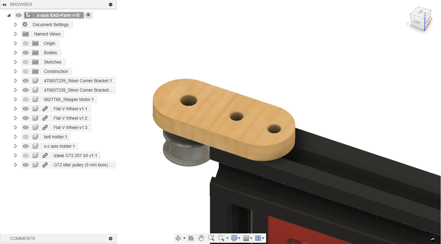
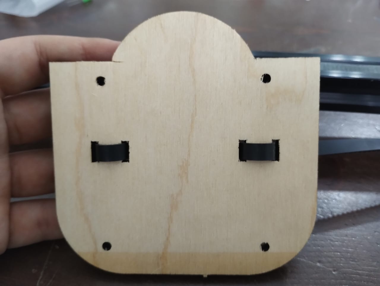
Here is the design of the part that is connected to the v wheels and will hold the z axis. It was also taken from the creality ender 3 and made an offset of the outline, added holes to connect to the belt holder part, and another ones to connect to z axis. The main important thing in this part is that the distance between the centers of the v wheel holes should be exact 40mm, nothing more, nothing less.
Then I worked on the belt holder part. This way was inspired from our backpacks shoulder. We take the belt from one side in put it to the other one and it's tensioned well. Luckily it worked just fine.
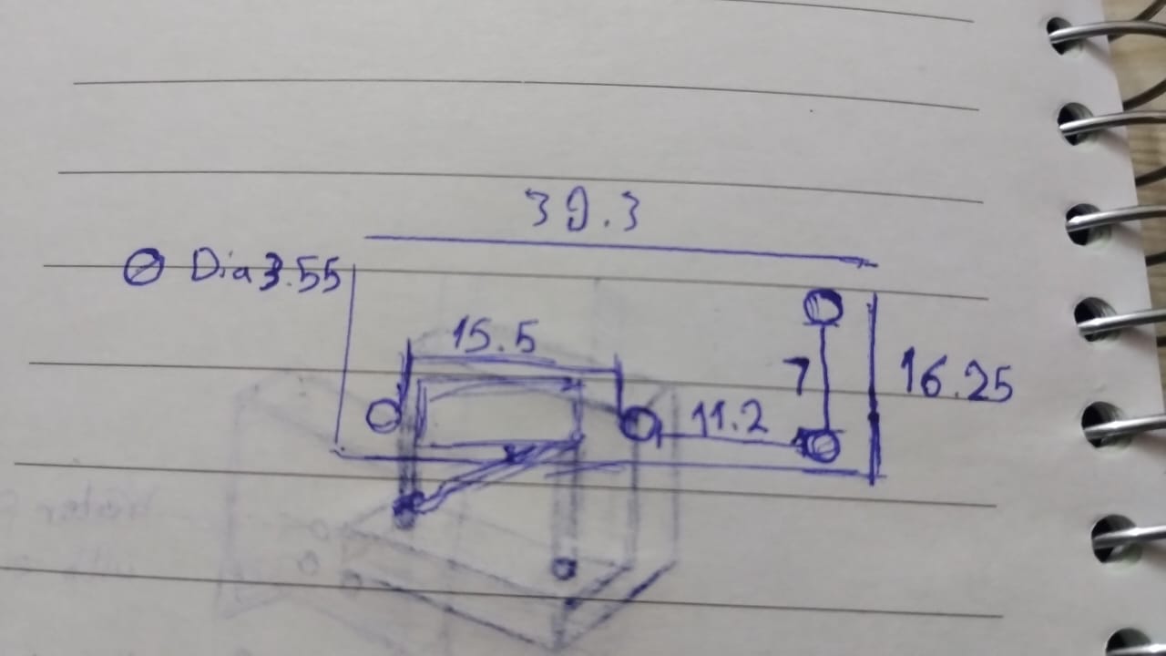
Next I needed to work on the limit switch holder and I didn't find a 3D model of it with the same exact size so I started measuring using the caliper and wrote down the measurements to start sketching it on Fusion.
This is the part I designed to hold the Nema 17 Stepper motor and the limit switch. I added 2 holes to use T-Nut to hold the part to the frame. I projected the stepper motor face to make the part that holds it and sketched the limit switch holder.
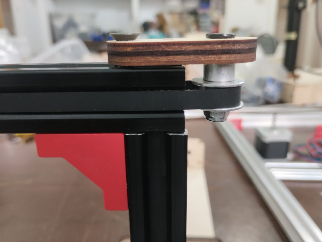
This is the part that was in the creality ender 3 and I used it in my design to hold the idler pulley.
That's it but just in 6mm plywood.
--------------------------------------------------------------------------------------------------------------------
2. X-Axis Fabricate - Table Saw & Laser-Cut & 3D Print
The fabrication proccess was on 3 main machines: 3D printer for 3D parts, Laser Cutter for 2D parts, and Table Saw to cut the aluminium frame.
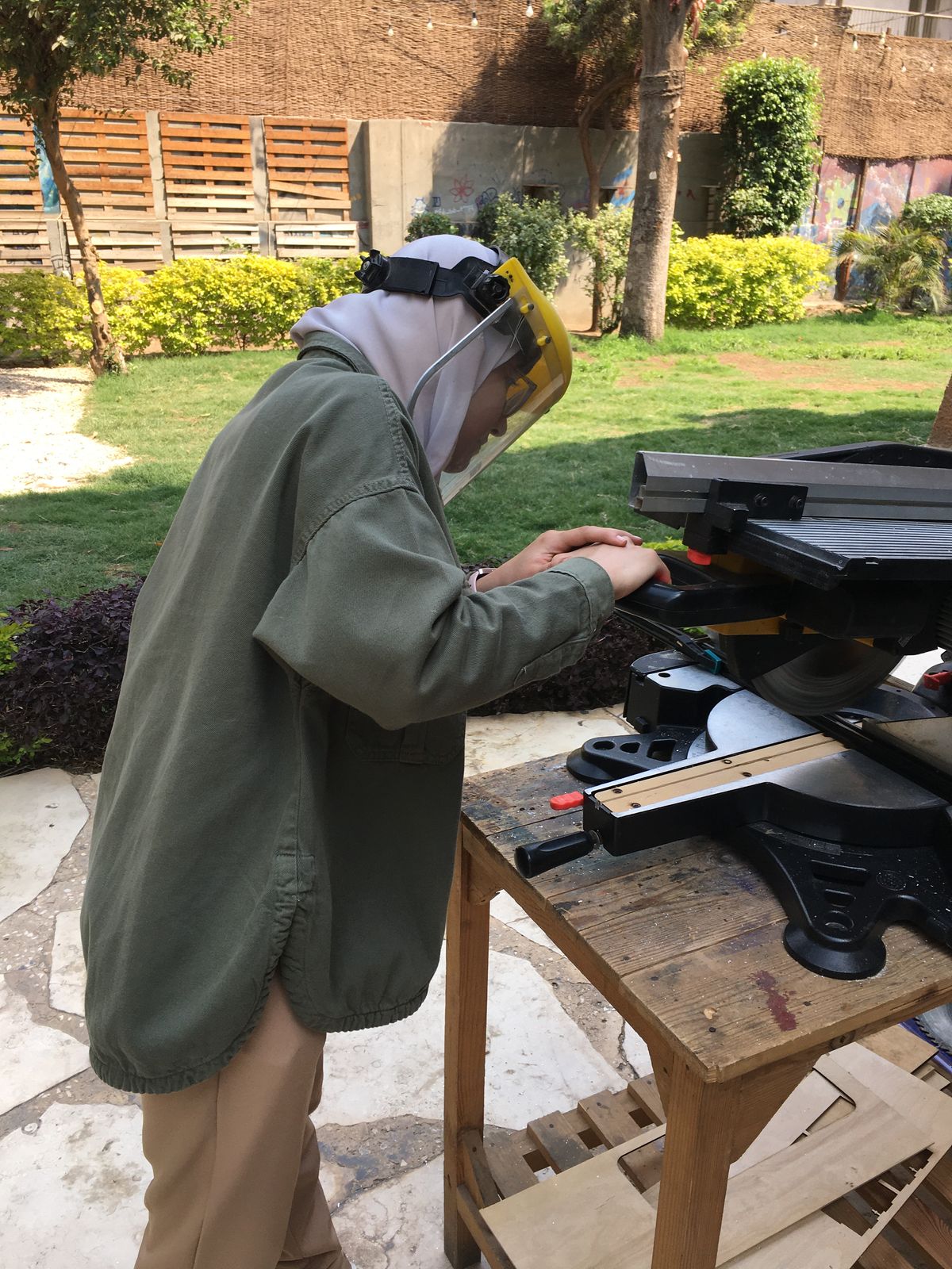
2.1. Table Saw:
This was my first time using this table saw and my friend Eman and Eng. Omar Seif helped me use it. I cut a 491mm frame and another two 170mm frames.
2.2. Laser-Cut:
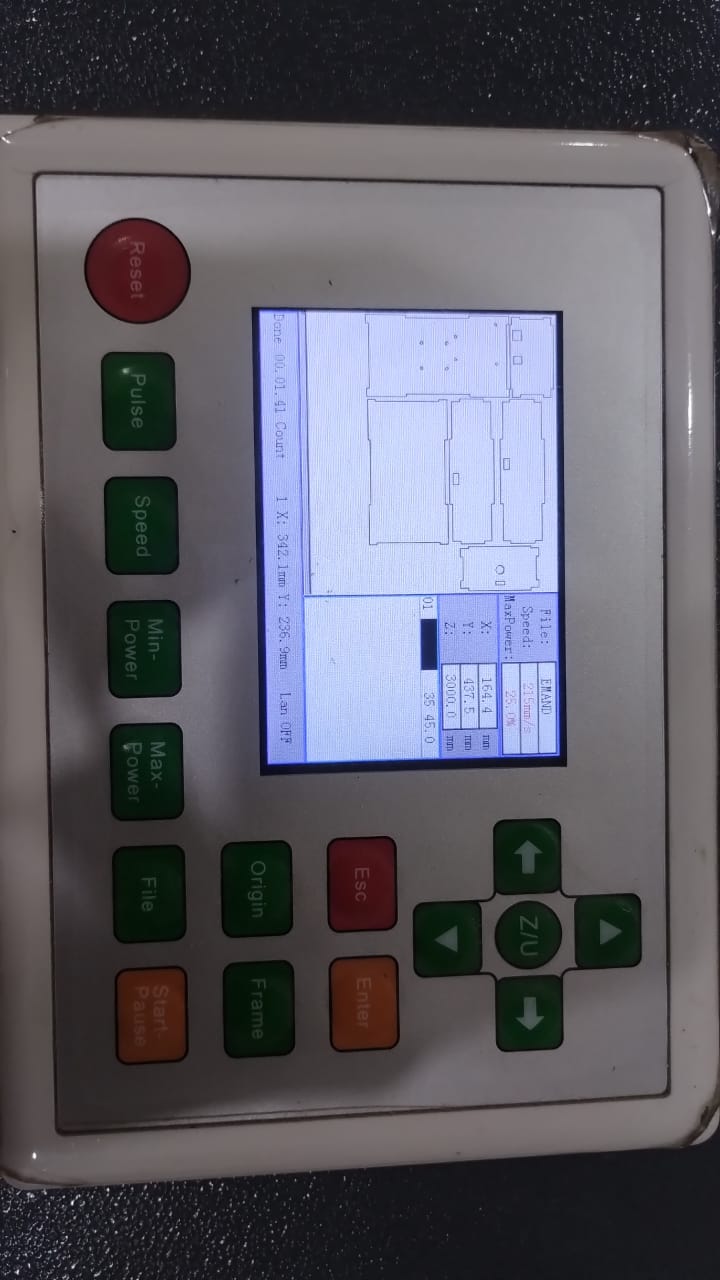
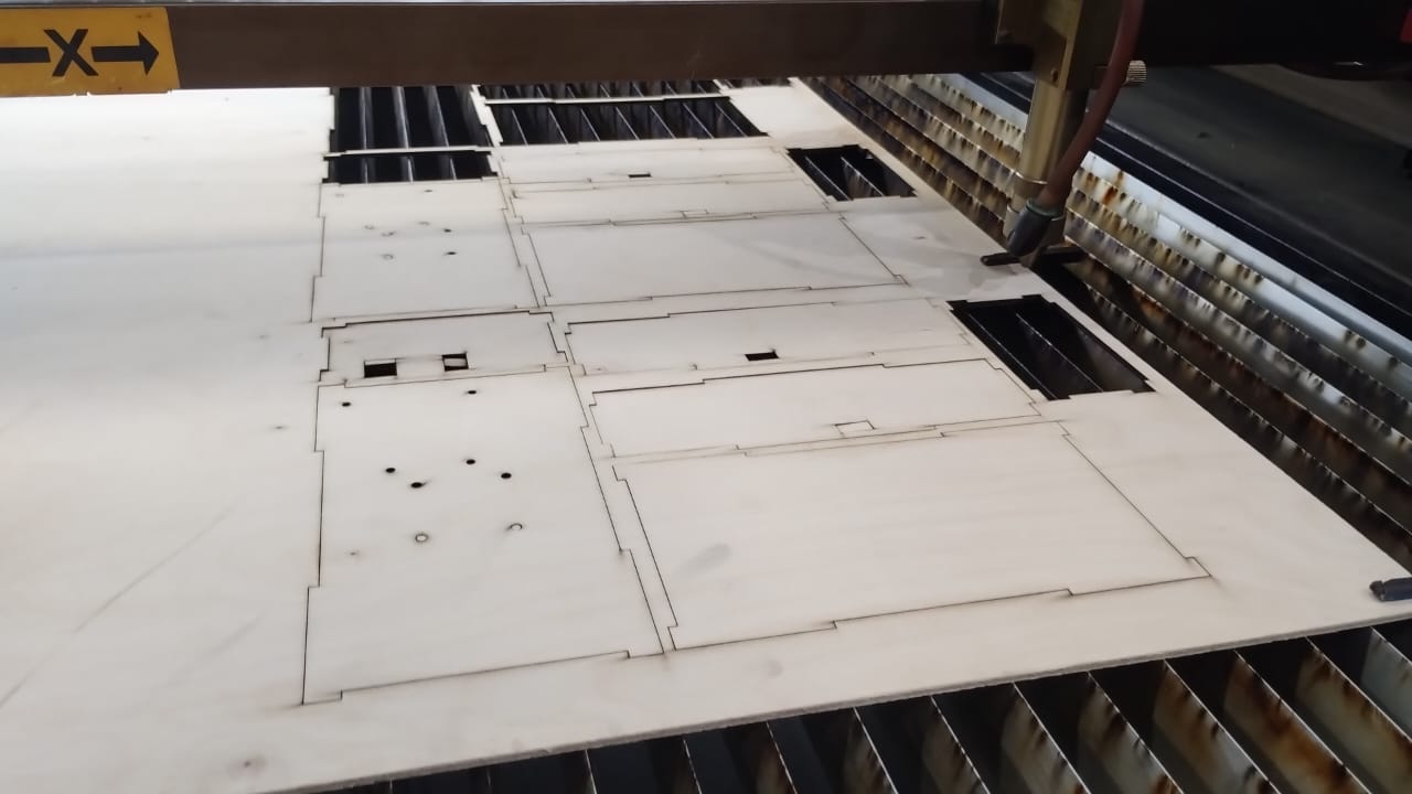
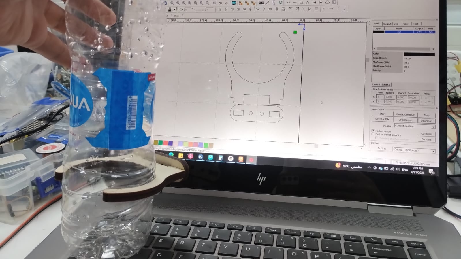
To laser Cut the parts I exported sketches from Fusion then used RDWorks V8 to prepare them for cutting and cut 6mm Plywood on Elmalky Laser Cutter.
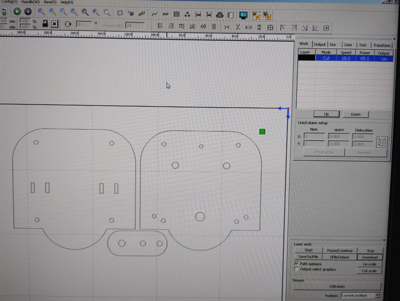
Preparing the files on RD Works V8.
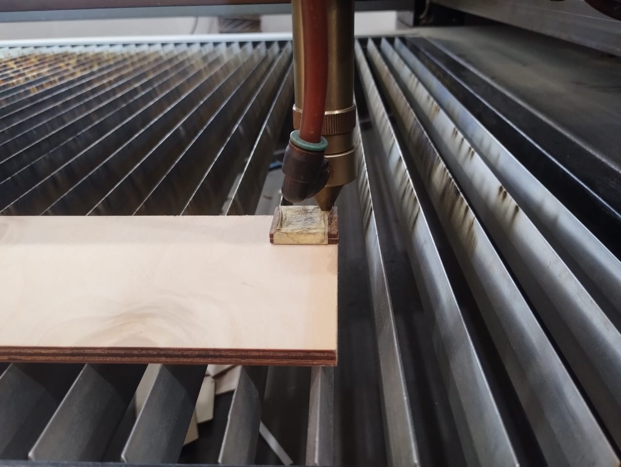
Adjusting the focus of the Laser Cutting Machine.
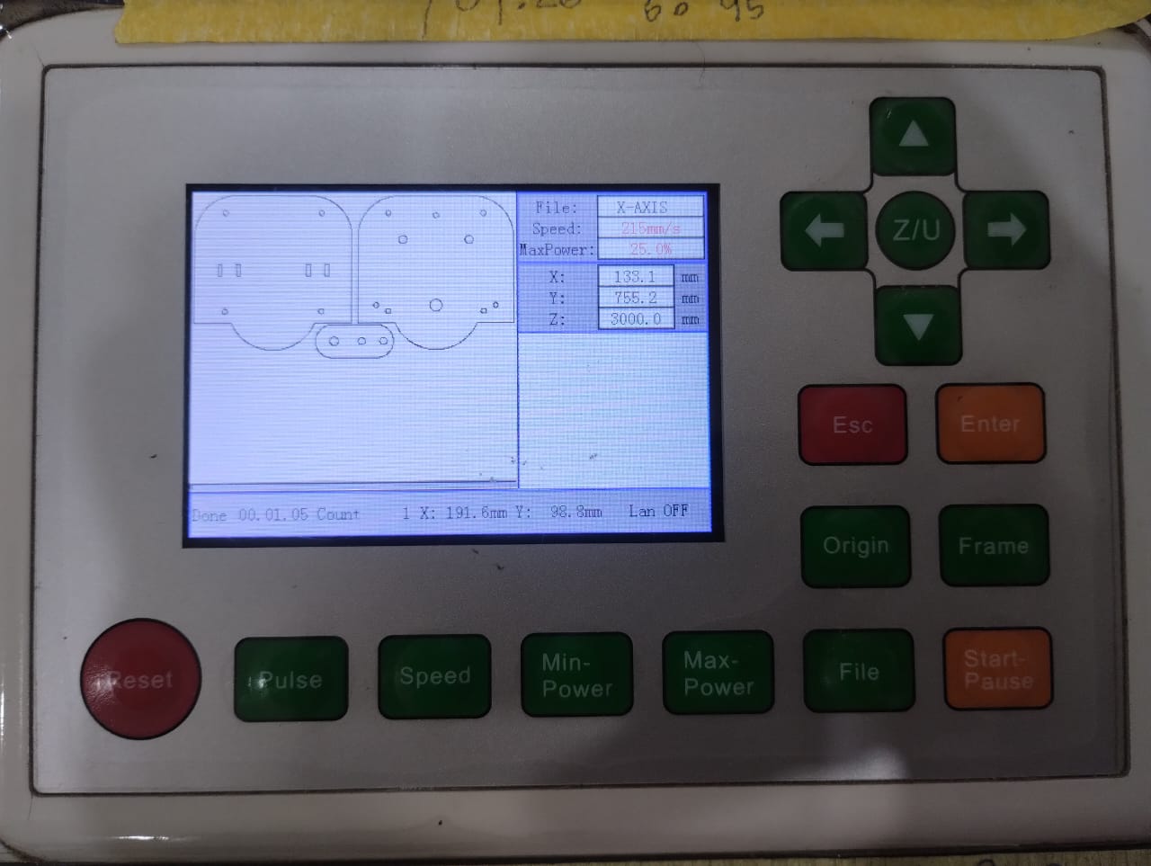
Preview From the Machine.
Here I was Cutting the electronics box which Amr designed.
Cutting on a 3mm Plywood.
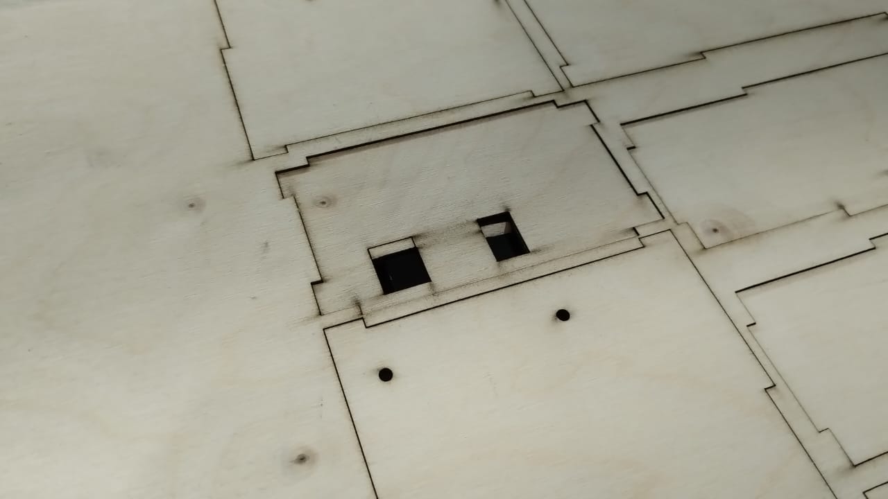
Here there was a tiny problem in the design and Amr suggested we put the part in the same spot and re-cut again this part only with the right design.
2.3. 3D Print:
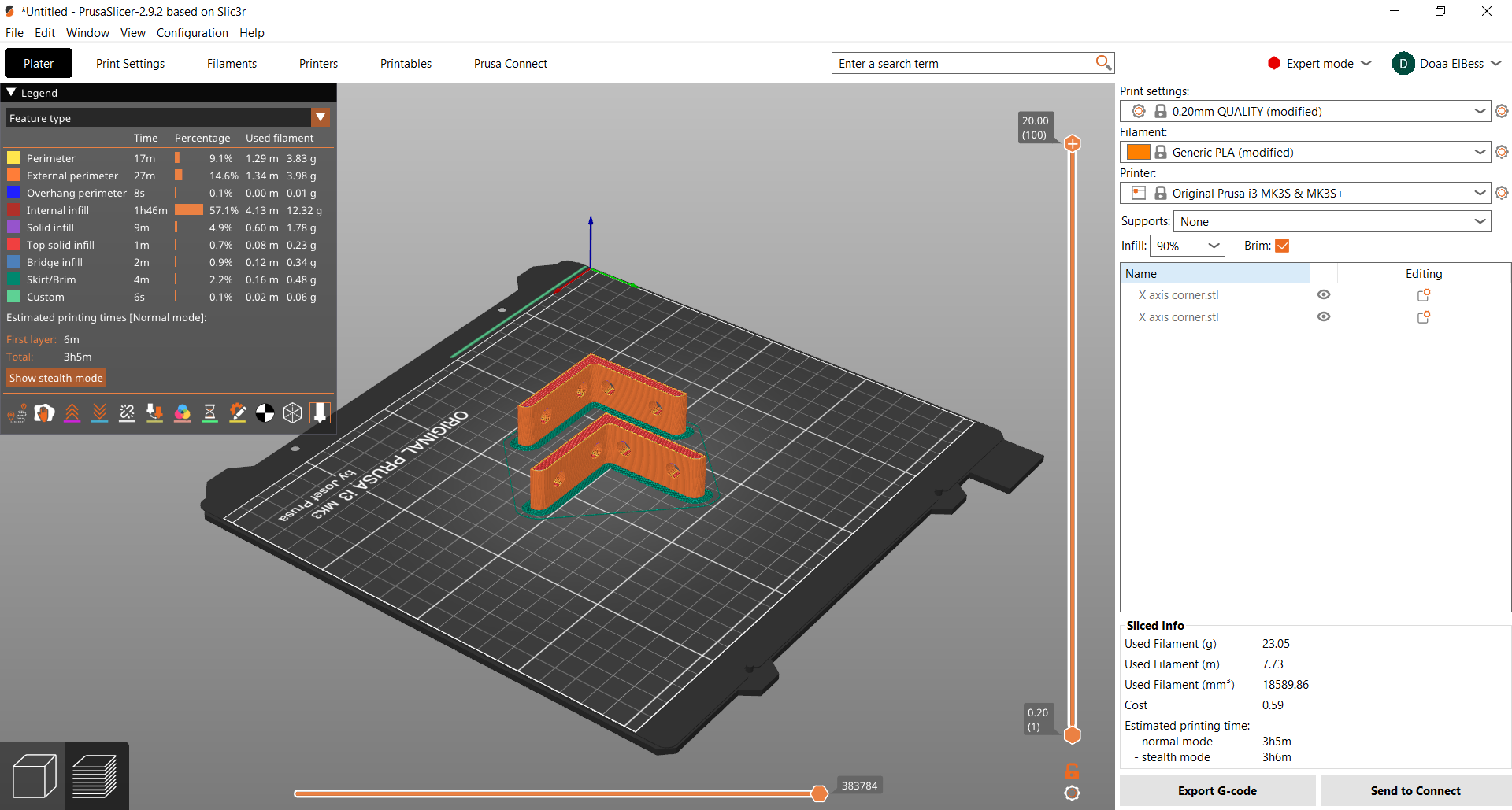
For this part of fabrication we had all of our prusa printers busy so it was time to deal with a new 3D printer to me which was Creality Ender 3-V2. And also I used the Prusa i3 MK3S for another parts another day. I decided to make it a whole new experience so I decided to use Prusa Slicer for preparing the files to 3D print instead of Cura that I was used to use.
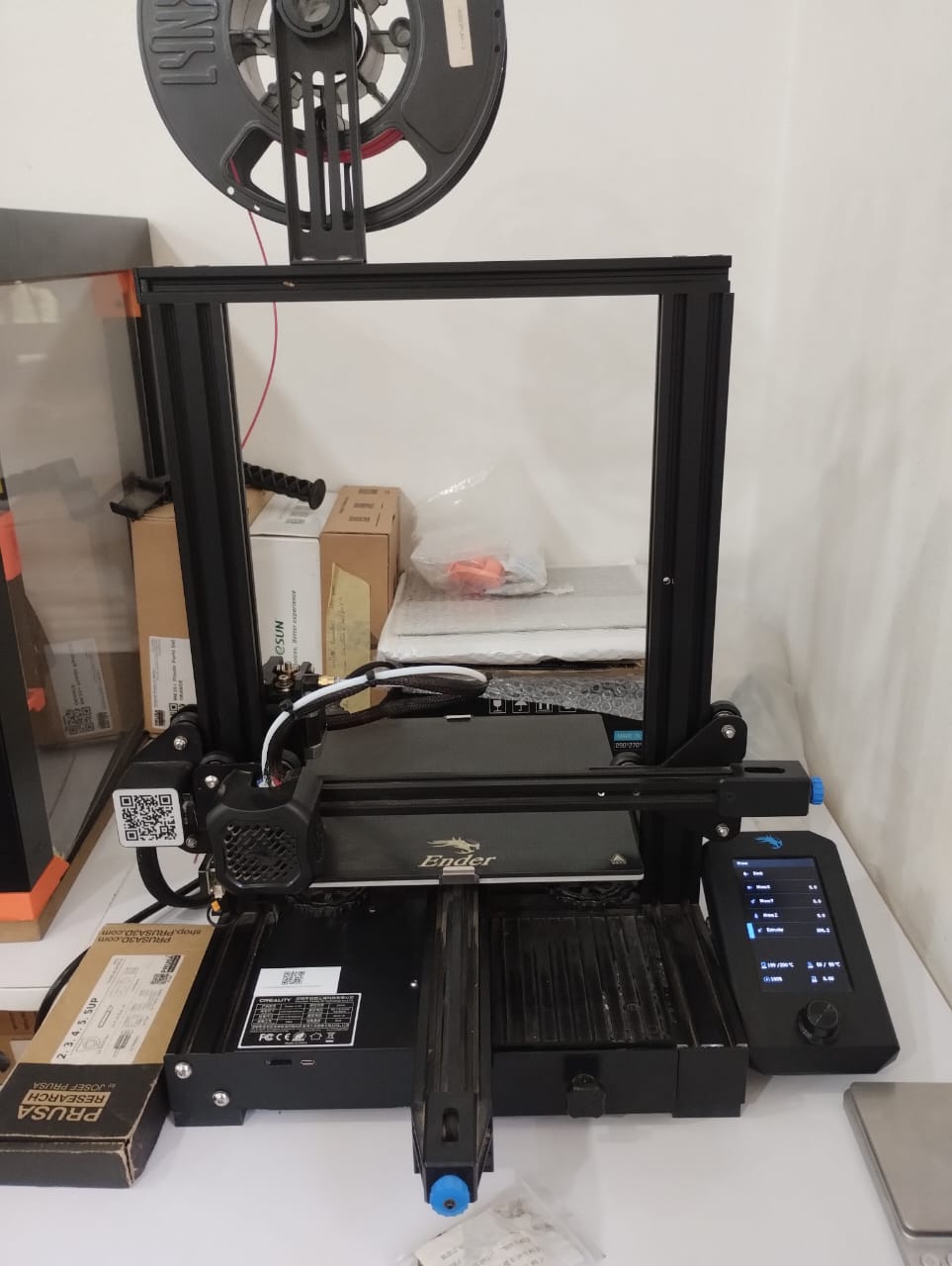
This is the Creality Ender 3-V2 where we have to level the bed ourselves. See The Video to know how.
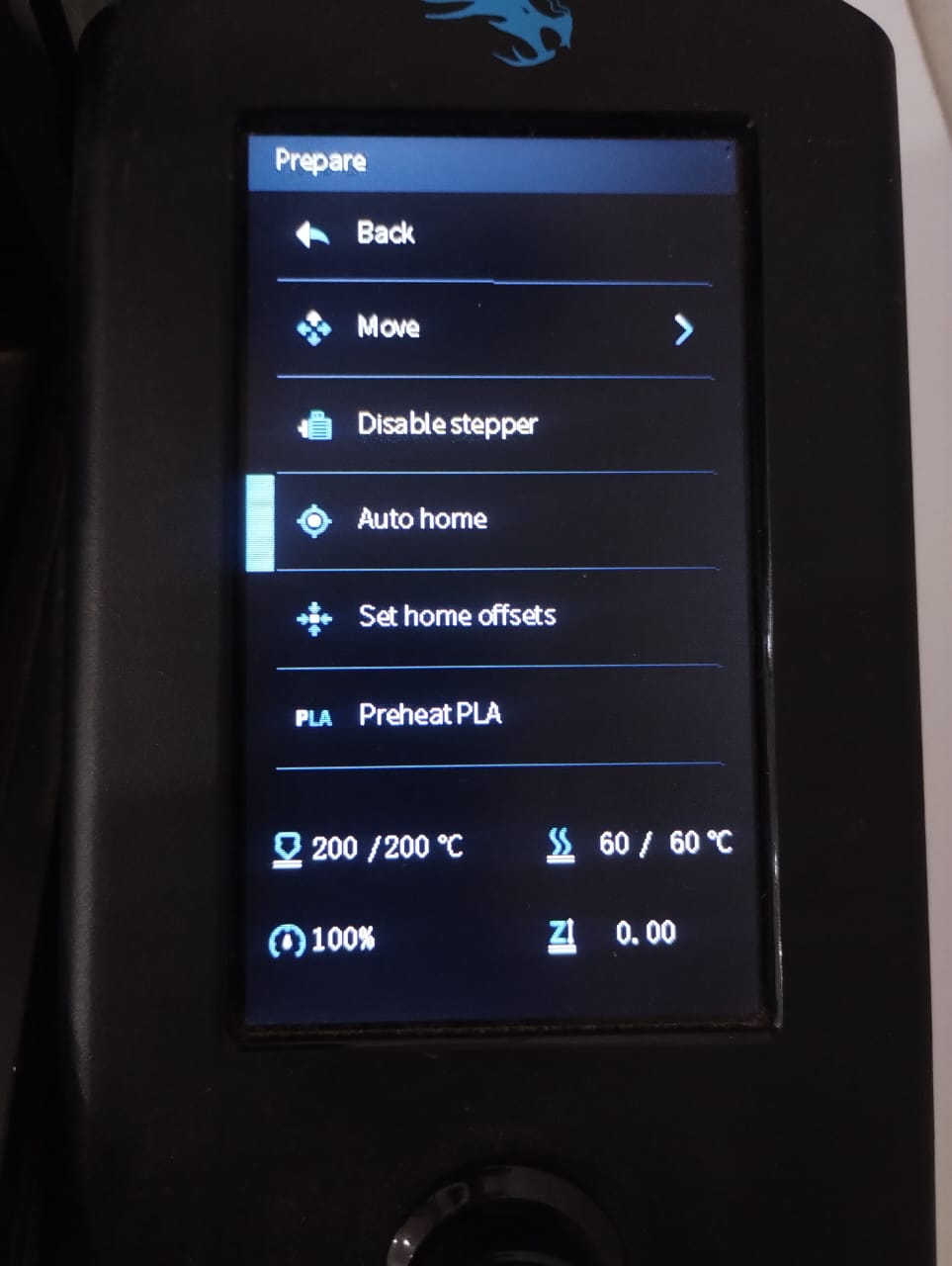
First I went to the prepare menu and chose auto home and preheated PLA to start adding filament.
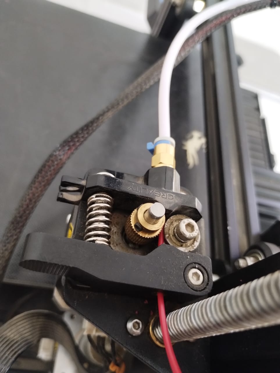
This is where we add filament. It's a bit tricky as I have to press a part and push the filament towards a hole I can't even see clearly but I managed to do it.
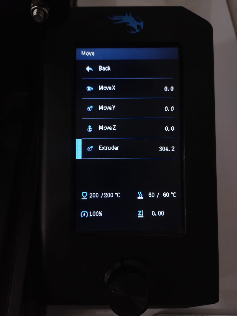
From move I turn the knob for the extruder to push the filament through it.
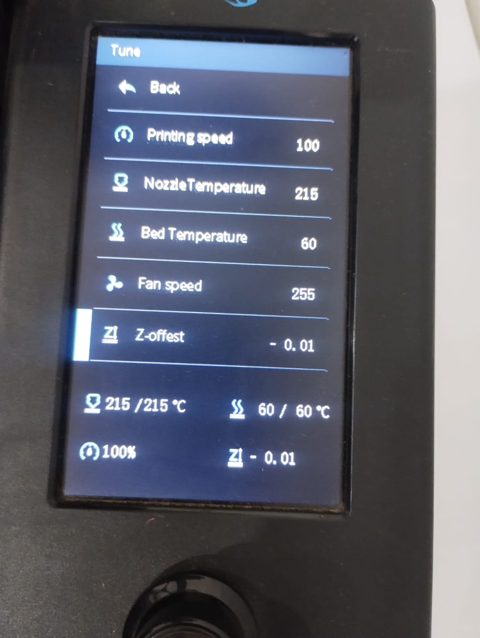
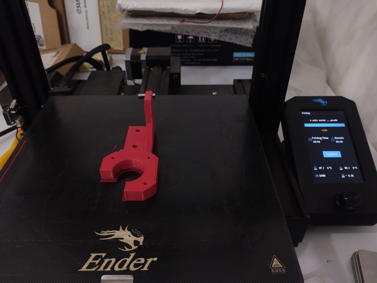
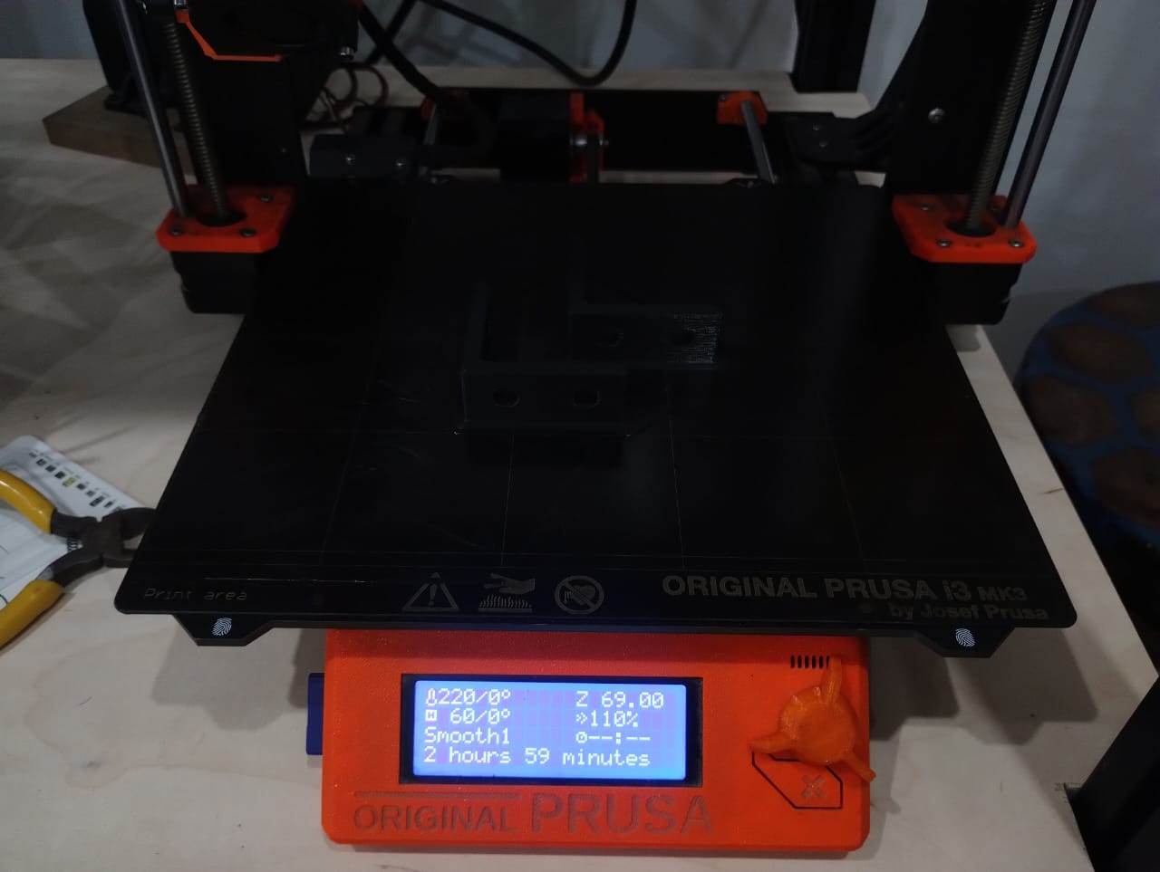
After I level the bed and I start printing and while watching the first layer I might need to adjust the z-offset to get a better first layer.
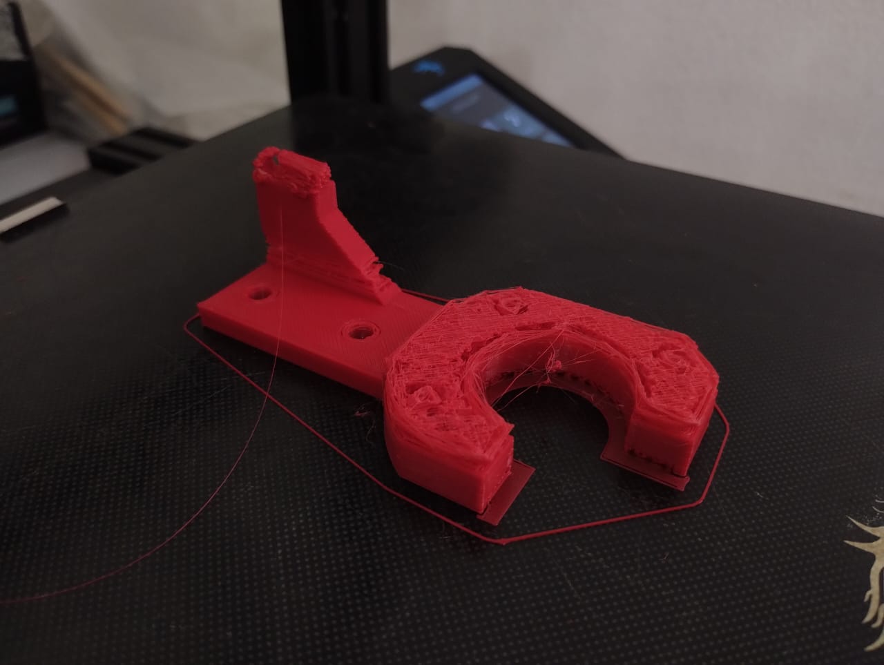
My first print was a failed one. I left the printer and when I returned I found it that way so I needed to re-print it.
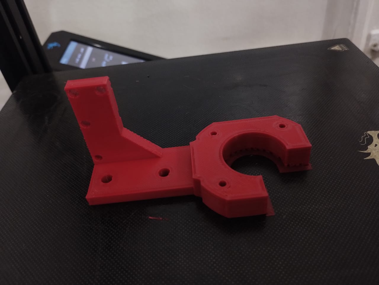
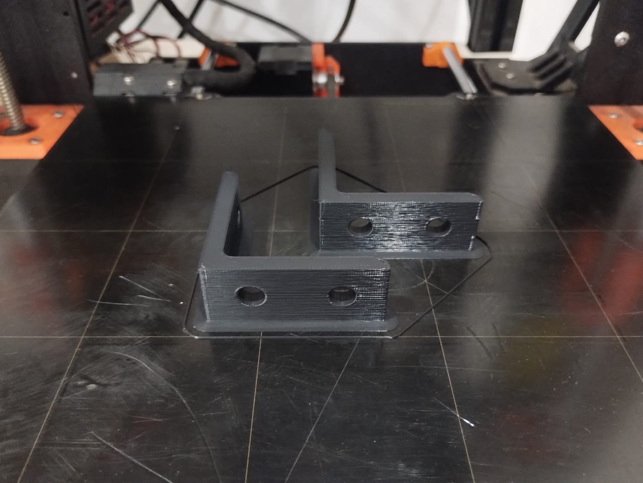
This was the second trial where I was watching over the 3D printer as it prints and finally it was a good one.
Another wide angle celebrating the success print.
Next I prepared the corners to be printed on the prusa i3 mk3s.
Printing them in black filament.. Bikaaa
Boooo..
--------------------------------------------------------------------------------------------------------------------
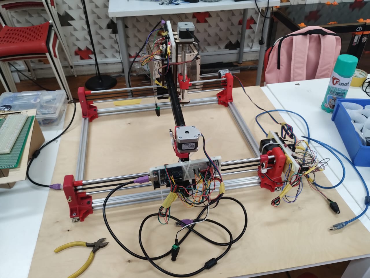
3. X-Axis Assembly
After all this fabrication it was now time for assembly.
First I started with the frame and added the corners to it. At first I used the corners that Amr printed but later I changed them because they didn't hold my frame well. Then I moved to the idler pulley.
This is how I assembled the belt.
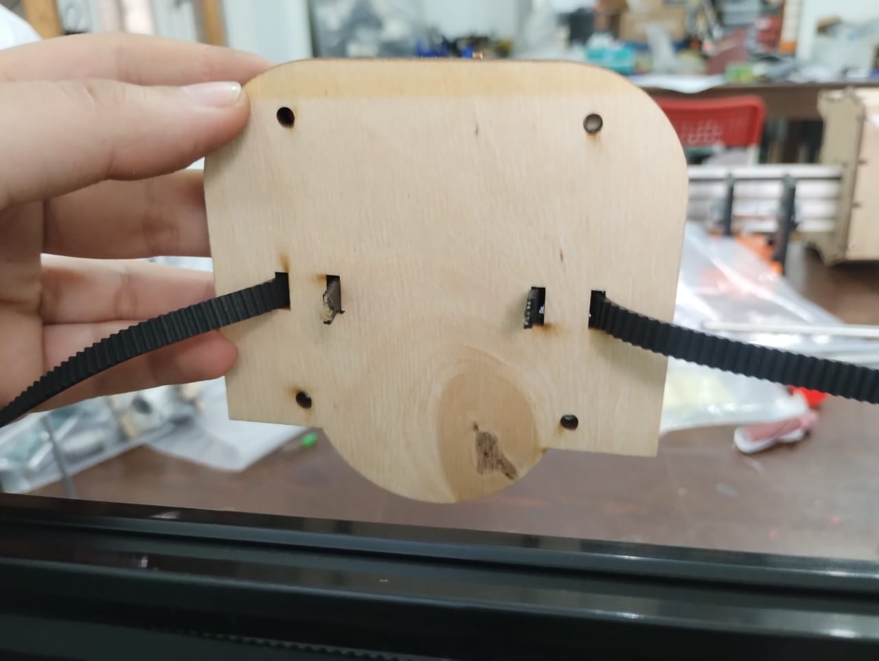
A back view of the belt assembly.
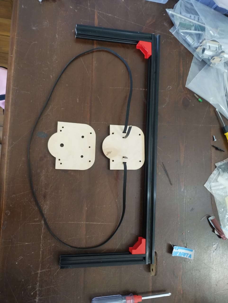
Assembly in progress...
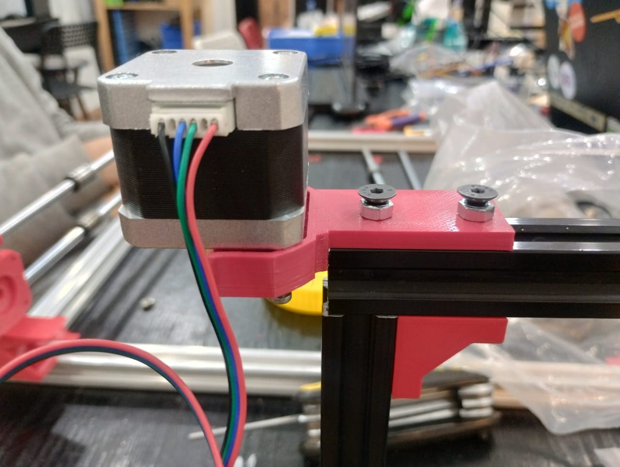
Bad news that the stepper motor we had wasn't the same shape as the one I used in the design. The good news was that they had the same holes to screw.
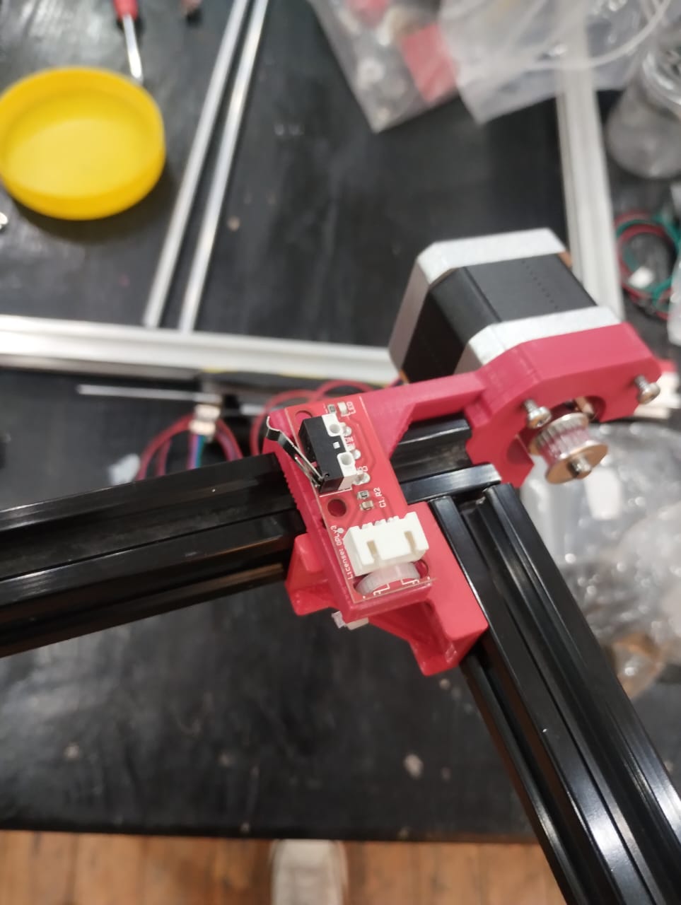
I assembled the limit switch using zip tie but I guess next time if I redesigned this I will pay more attention to where I put the limit switch and make sure the screws have place to go.
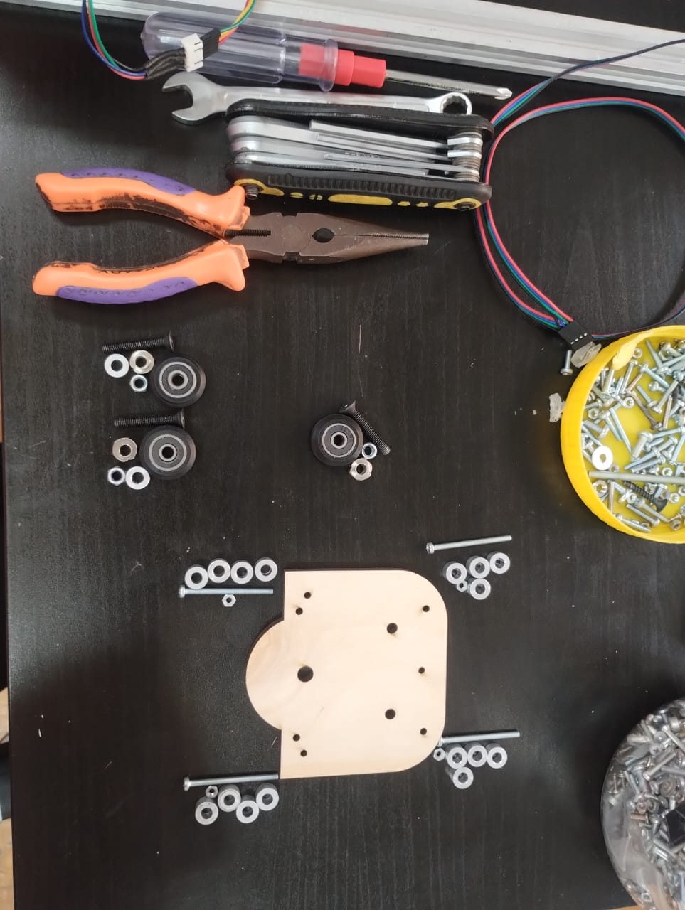
Don't panic it's just V-Wheels assembly parts and tools. Some M5 screws, nuts, and washers. Also M3 and spacers, and every tool you can get your hand on. Important part of this assembly is the eccentric nut. This is a nut that it's center is not exactly in center. So you put it in one wheel and turn it till you have all the wheels moving smoothly.
Looking smooth yea!! Let's see what it does when it's moved by stepper motor..
--------------------------------------------------------------------------------------------------------------------
4. Stepper Motor Test
This part was mainly depending on the big hacker, coder, mechatronics engineer Amr. As he started programming and I just followed his steps and helped a little bit in trouble shooting.
int xdirectionPin = 10;
int xstepsPin = 9;
int xlimitSwitch = 11;

int microStepping = 1;

int betweenStepsDelay = 1000;  // in Microseconds

int steps_fullRevolution = 200;
int gearBeltPitch = 2;  // in mm
int numteeth = 20;

int wantedDistance;
int wantedSteps;

void setup() {
  Serial.begin(9600);
  pinMode(xdirectionPin, OUTPUT);
  pinMode(xstepsPin, OUTPUT);
}

void loop() {
  digitalWrite(xdirectionPin, 0);

  if (Serial.available()) {
    char command = Serial.read();  // read once and store
    if (command == 'S') {
      wantedSteps = Serial.parseInt();
      for (int mystep = 0; mystep <= wantedSteps; mystep++) {
        digitalWrite(xstepsPin, HIGH);
        delayMicroseconds(betweenStepsDelay);
        digitalWrite(xstepsPin, LOW);
        delayMicroseconds(betweenStepsDelay);
      }


    } else if (command == 'D') {
      wantedDistance = Serial.parseInt();  // Get distance in mm
      wantedSteps = (steps_fullRevolution * microStepping * wantedDistance) / (gearBeltPitch * numteeth);
      for (int mystep = 0; mystep <= wantedSteps; mystep++) {
        digitalWrite(xstepsPin, HIGH);
        delayMicroseconds(betweenStepsDelay);
        digitalWrite(xstepsPin, LOW);
        delayMicroseconds(betweenStepsDelay);
      }
    }
  }
}
That was the initial code that we used to test the stepper motor steps and distance with the belt. It mainly worked by when we write S and a number it moves the steps number and every 200 steps is one revolution. When we write D and a distance in mm like 10 it goes to the equation and does the math then moves the 1CM.
The contribution I did in this code that first the first written command in the code only works. If it's S only steps work and if it's D only distance works. I figured out that this was something in how the code is written but I'm not a good coder so I went to chatGPT and told him what I think and provided it the code. It told me that we shouldn't write if Serial.read, but we store it in a variable first (Command) for example and then say if command is, so each time it goes to check what's in the variable.
--------------------------------------------------------------------------------------------------------------------
5. Code Spiral Development
To get to the final code we decided to work in spirals. We forst made sure the stepper motor works and goes forward. Ok, Lets make it go in the other Direction and make it go home.
int xdirectionPin = 10;
int xstepsPin = 9;

int microStepping = 1;

int betweenStepsDelay = 1000;  // in Microseconds

int steps_fullRevolution = 200;
int gearBeltPitch = 2;  // in mm
int numteeth = 20;

int wantedDistance;
int wantedSteps;

char rightcommand = 'R';
char leftcommand = 'L';
char homecommand = 'H';

int sensor = 11;
int sensorval;

int homingOffset = 10;  // in mm

void right() {
  digitalWrite(xdirectionPin, 0);
}

void left() {
  digitalWrite(xdirectionPin, 1);
}

void setup() {
  Serial.begin(9600);
  pinMode(xdirectionPin, OUTPUT);
  pinMode(xstepsPin, OUTPUT);

  pinMode(sensor, INPUT);
}

void loop() {
  //moves away from home
  digitalWrite(xdirectionPin, 0);

  if (Serial.available()) {
    char command = Serial.read();  // read once and store
    if (command == 'R') {
      wantedDistance = Serial.parseInt();  // Get distance in mm
      wantedSteps = (steps_fullRevolution * microStepping * wantedDistance) / (gearBeltPitch * numteeth);
      for (int mystep = 0; mystep <= wantedSteps; mystep++) {
        right();
        digitalWrite(xstepsPin, HIGH);
        delayMicroseconds(betweenStepsDelay);
        digitalWrite(xstepsPin, LOW);
        delayMicroseconds(betweenStepsDelay);
      }


    } else if (command == 'L') {
      wantedDistance = Serial.parseInt();  // Get distance in mm
      wantedSteps = (steps_fullRevolution * microStepping * wantedDistance) / (gearBeltPitch * numteeth);
      for (int mystep = 0; mystep <= wantedSteps; mystep++) {
        left();
        digitalWrite(xstepsPin, HIGH);
        delayMicroseconds(betweenStepsDelay);
        digitalWrite(xstepsPin, LOW);
        delayMicroseconds(betweenStepsDelay);
      }
    } else if (command == homecommand) {
      Serial.println("HOMING !!!");
      digitalWrite(xdirectionPin, 1);
      while (digitalRead(sensor)) {
        //Serial.println("s");
        digitalWrite(xstepsPin, 1);
        delayMicroseconds(betweenStepsDelay);
        digitalWrite(xstepsPin, 0);
        delayMicroseconds(betweenStepsDelay);
      }
      wantedSteps = (steps_fullRevolution * microStepping * homingOffset) / (gearBeltPitch * numteeth);
      for (int steps = 0; steps <= wantedSteps; steps++) {
        //Serial.println("E");
        right();
        digitalWrite(xstepsPin, 1);
        delayMicroseconds(betweenStepsDelay);
        digitalWrite(xstepsPin, 0);
        delayMicroseconds(betweenStepsDelay);
      }
    }
  }
}
Here we made it go left for a distance, right for a distance, and home it goes to the limit switch and clicks it then move away 1CM away from it.
After that we had some thoughts:
Here we was testing limiting going backwards.
After assembling all axis together we wanted to test homing for all of our axis together. Starting with Eman presented in Z-Axis, Then me presented in X-Axis, and finally Amr with Y-Axis. (Crowds cheering)
Then we wanted to test irrigating process so we made a simple code of moving the axis and turning on the pump for several seconds then turn it of again.
Let's continue our spiral development in the code. We wanted to control all of the axis using a web interface and a master xiao board controlling arduino slaves using UART communiation. We started by one axis then started integrating other axis. A gentle Reminder "Remember to wire all grounds together". Here I was testing X and Y axis movement and homing.
I then added the last axis to the code and tested moving and homing them.
The final code of the X-Axis will be provided in the source files section.
The code of the master Xiao was generated using ChatGPT with the help of our instructor Saeed. It will be provided in the group assignment page with the prompts used.
--------------------------------------------------------------------------------------------------------------------
6. Soil Moisture Sensor Test
For this machine we had soil moisture sensor and water pump so we decided that I try them out at first and calibrate the sensor. Here I was testing the sensor and calibrating its readings.
I used the code provided in Here to test the sensor and changed the numbers based on the readings my sensor gets.
--------------------------------------------------------------------------------------------------------------------
7. Water Pumps Test
After finishing with the sensor which I had previous experience with I moved to the water pump and it was my first time dealing with it. I searched on google to know the wiring of it and how to code it.
This was my first pump to test. It did make sounds but the water didn't go through the tube. I didn't know what was wrong till I decided to move to the next pump. "I had a bag full of them".
I moved to sit on the floor to protect my Laptop and other electronics from the evil of water pumps and I started to try the pumps from the adapter directly just to see if they are working first. And we have a winner here, even with a tangled tube and from a distance it managed to move the water from cup to another.
// Define L298N control pins
int IN1 = 6;
int IN2 = 7;
int ENA = 5; // must be PWM-capable pin

void setup() {
  pinMode(IN1, OUTPUT);
  pinMode(IN2, OUTPUT);
  pinMode(ENA, OUTPUT);

  // Set direction
  digitalWrite(IN1, HIGH);
  digitalWrite(IN2, LOW);
}

void loop() {
    digitalWrite(ENA, HIGH);
  delay(5000);

    digitalWrite(ENA, LOW);
  delay(5000);
}
This was the code I tried later to control the pump after I made sure it was working fine.
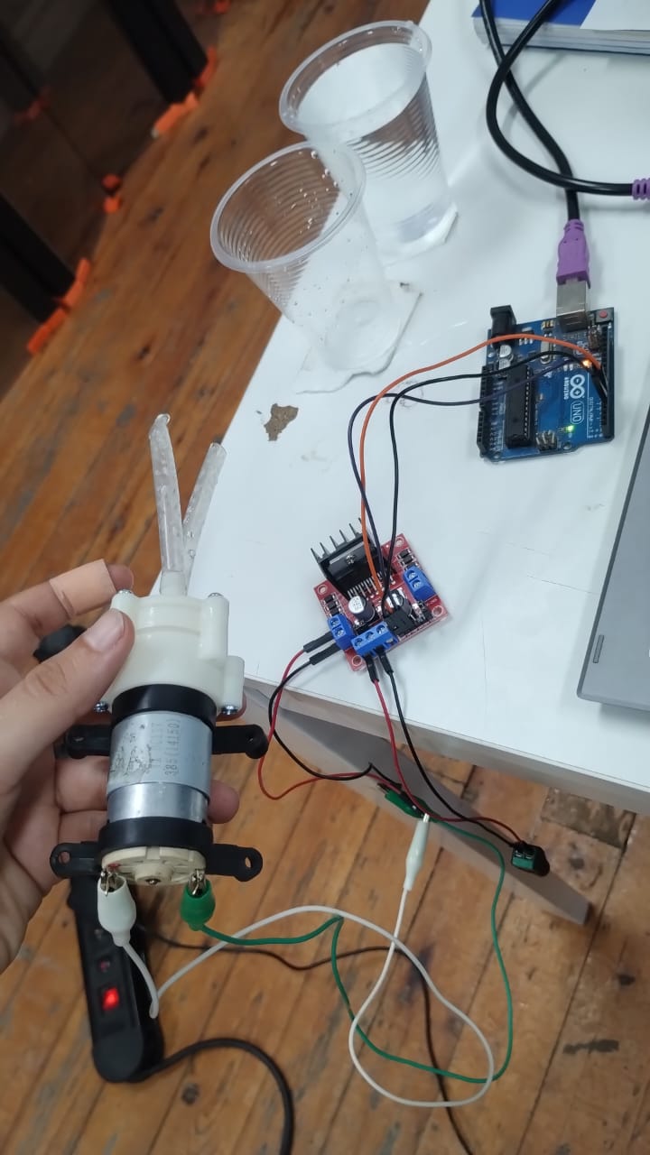
This is the wiring of the pump with the L298N Motor Driver and the most important pin is the ENA enable pin.
--------------------------------------------------------------------------------------------------------------------
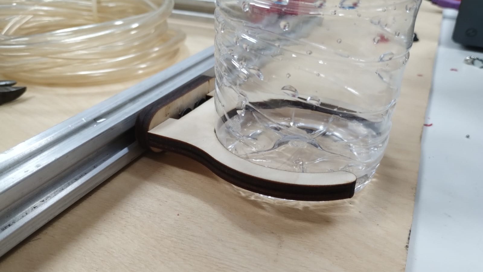
8. Water Tank Holder Design
Here we needed to make a holder to hold the water tank, in our case a small water bottle. So I worked on this..
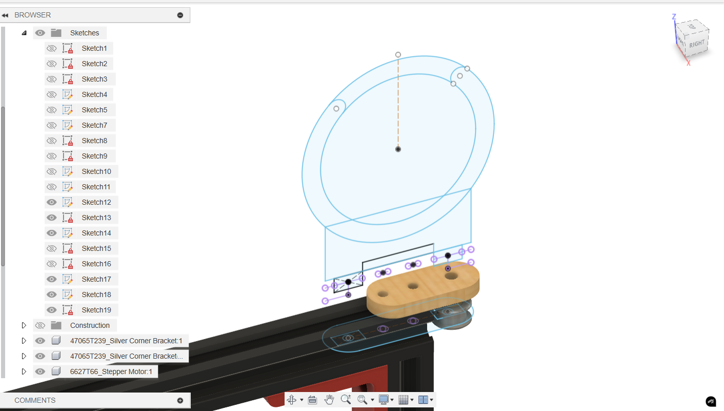
I started by sketching the holder of the tank holder with reference from the idler pulley holder then continued to sketch the holder itself.
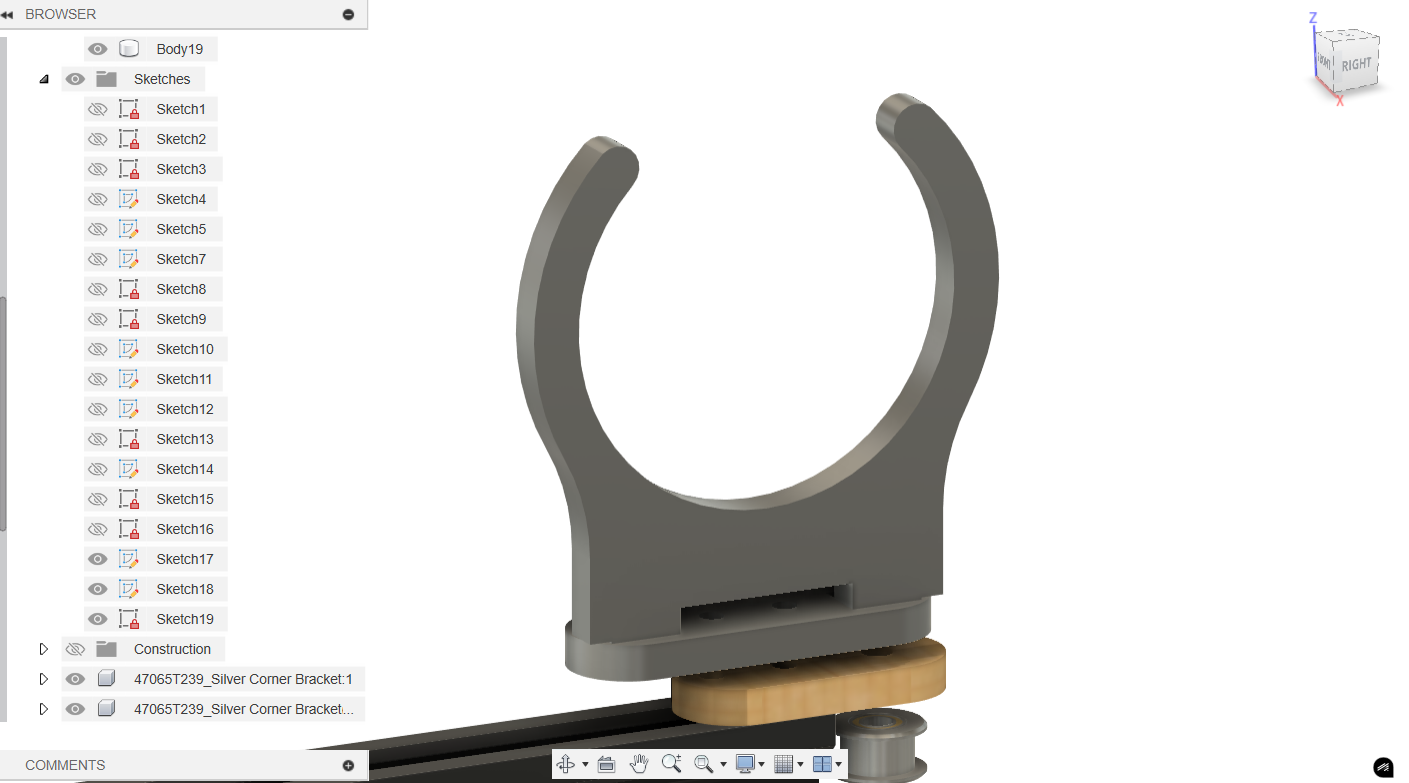
This is how it looked like with some fillets and the gap you see is for the screws heads.
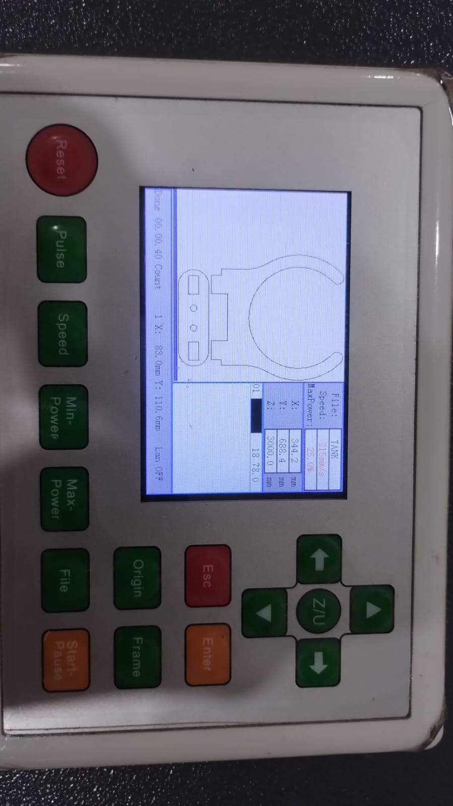
This was my first laser cut for the tank holder but it didn't fit well due to wrong kerf for the 6mm plywood.
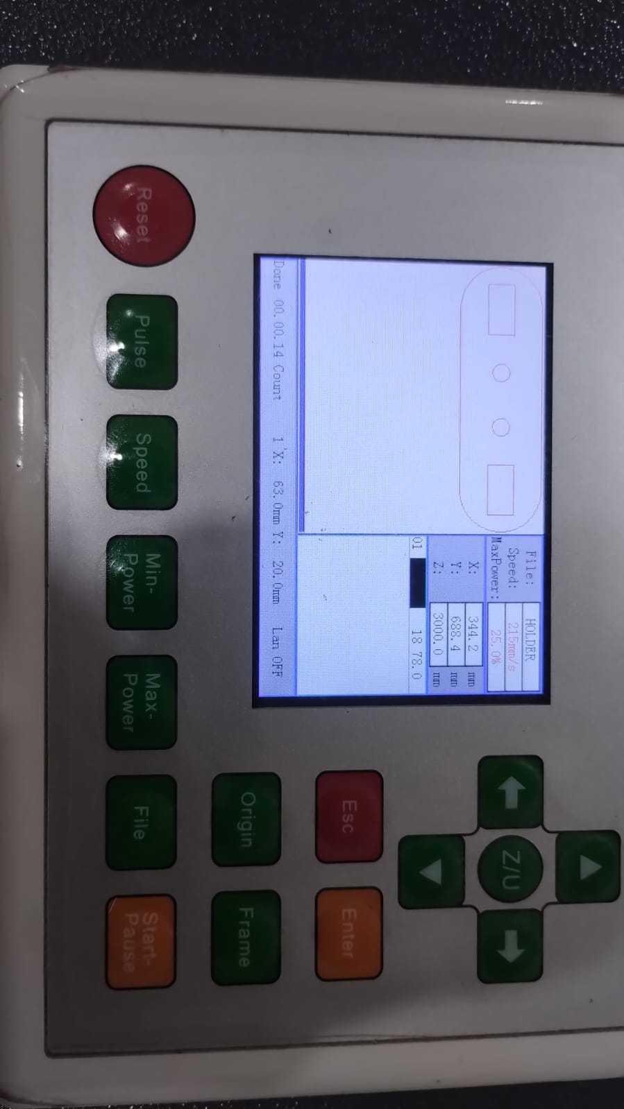
I made the rectangles a little bit bigger by removing the kerf in this part and it did fit perfectly.
--------------------------------------------------------------------------------------------------------------------
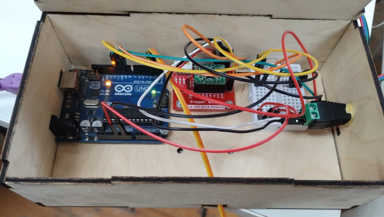
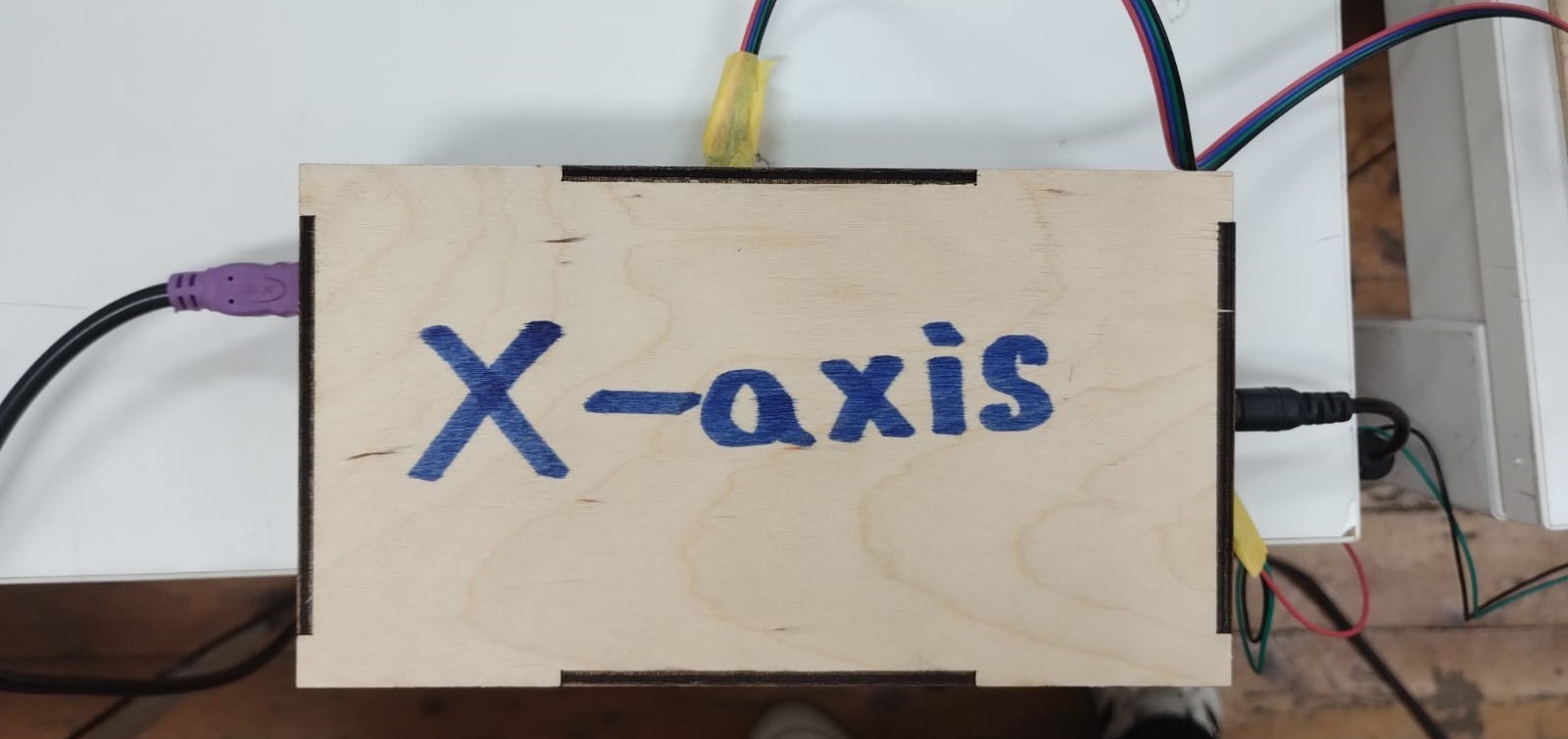
9. Cable Management and Final Wiring
This was the cable management we did at first and I thought it was good and enough. But actually it wasn't. Thanks to Amr's electronics boxes and Saeed's guide to how to make a good looking wiring and reduce the number of wires.
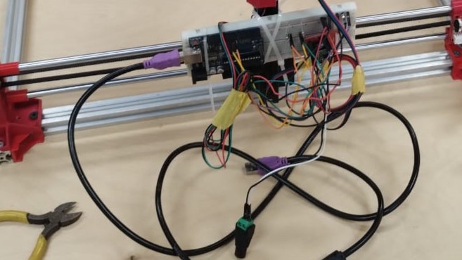
I went from this..
Then to this...
And this...
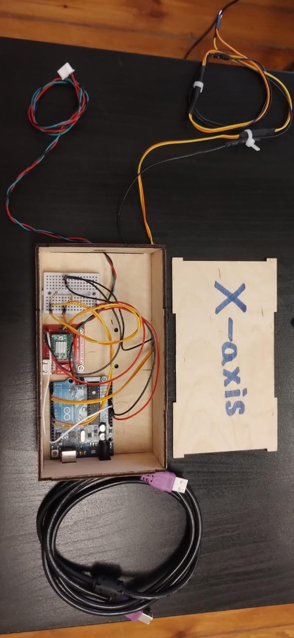
And finally to this....
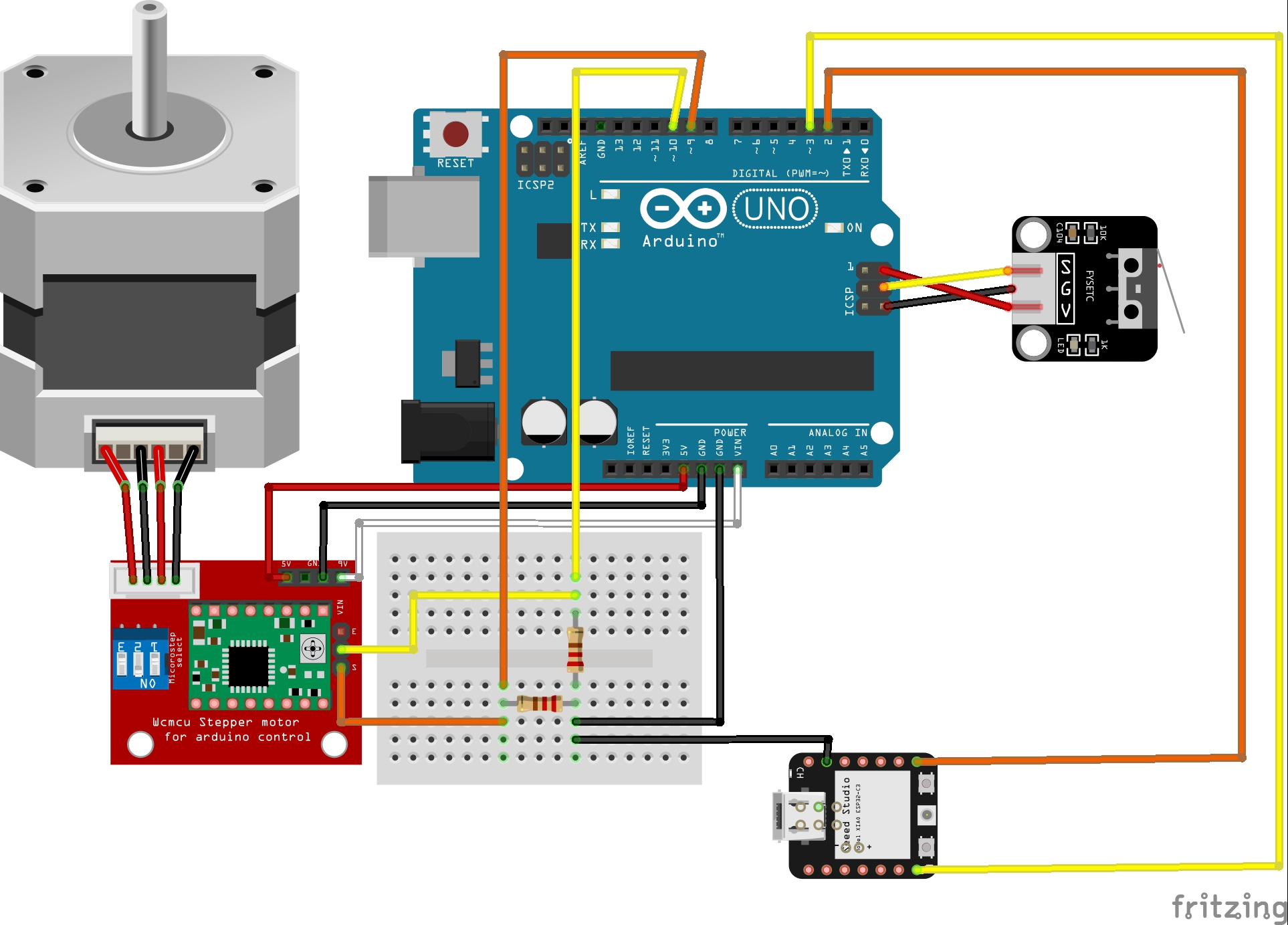
This is the final wiring done on fritzing. The limit switch module is not the same as used but it's the same wiring. Wiring it to these pins was interesting as Saeed told me these pins are actually: GND, MOSI(11), and VCC(5V).