
Embedded Programming
Here's a summary about what you'll see next:
- 1) Group Assignment:
-
- Exploring different toolchains and embedded architectures
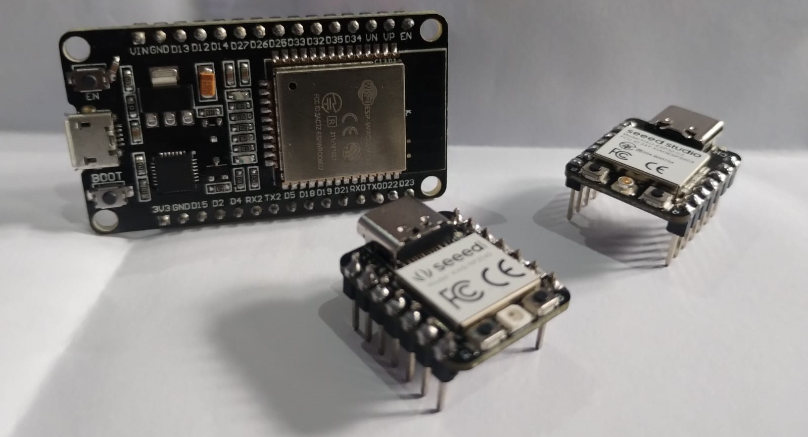
- XIAO RP2040
- EPS32-C3
- 2) Individual Assignment:
-
- Soil Moisture Sensor on OLED Simulation
- Wiring
- Coding
- 3) Extras:
-
- Physical Testing on Real Boards
- ESP-NOW Communication
- Testing components and codes
- Rolling Dice on a Led Matrix
1) Group Assignment
1. Exploring different toolchains and embedded architectures
We started the week by defining what each term mean in the programming language mean. For Example:
- Toolchain: is the software tool used for coding a specific Embedded Architecture
- Embedded Architecture: is the hardware part that we program like microcontrollers. And each one have different features and capabilities.
2. XIAO RP2040
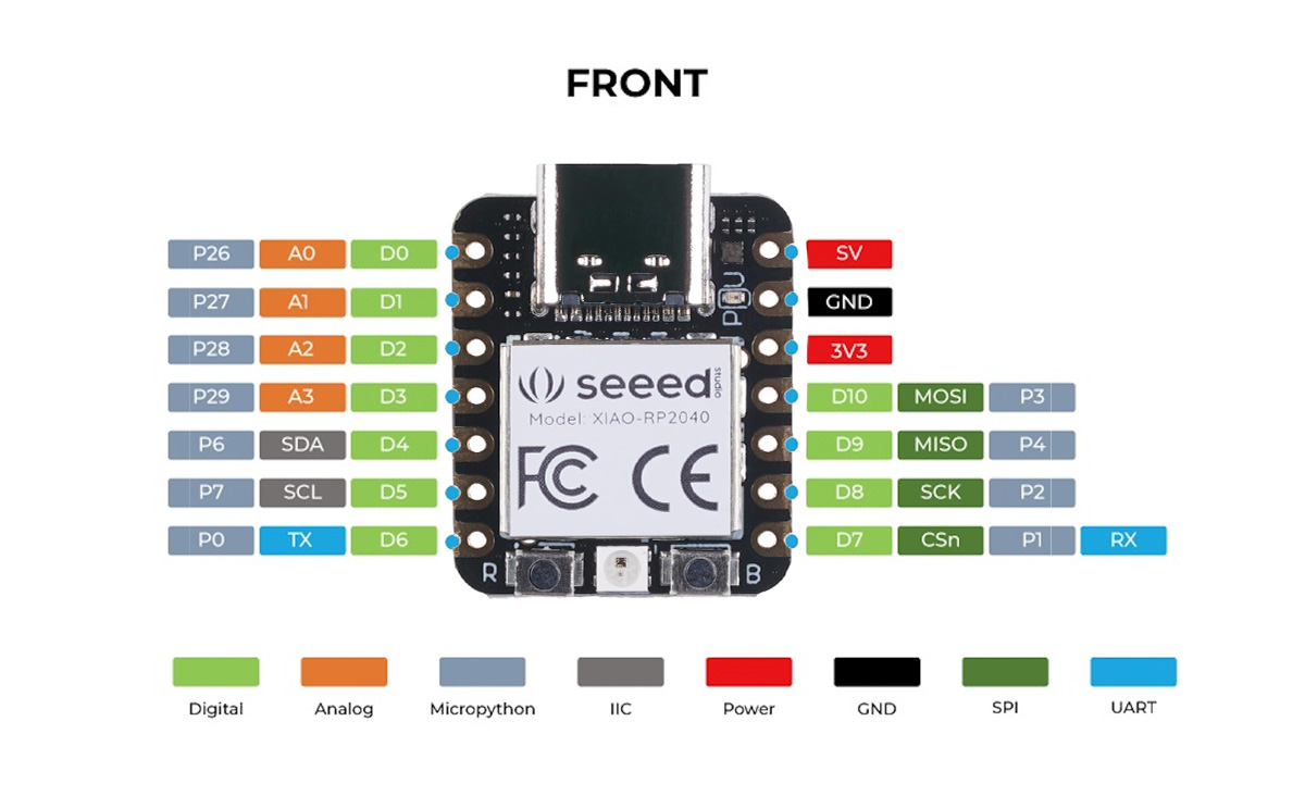
To Start using this microcontroller I needed to know more about it and its pins and other features. As it was made by Seeed Studio, they have a getting started page for each board so I walked through Getting Started with Seeed Studio XIAO RP2040 to know more.
To test this board I walked through This Link which gave me a step by step instructions to coding the XIAO RP2040 using Thonny and MicroPython.
Blinking RP2040
RGB Test on RP2040
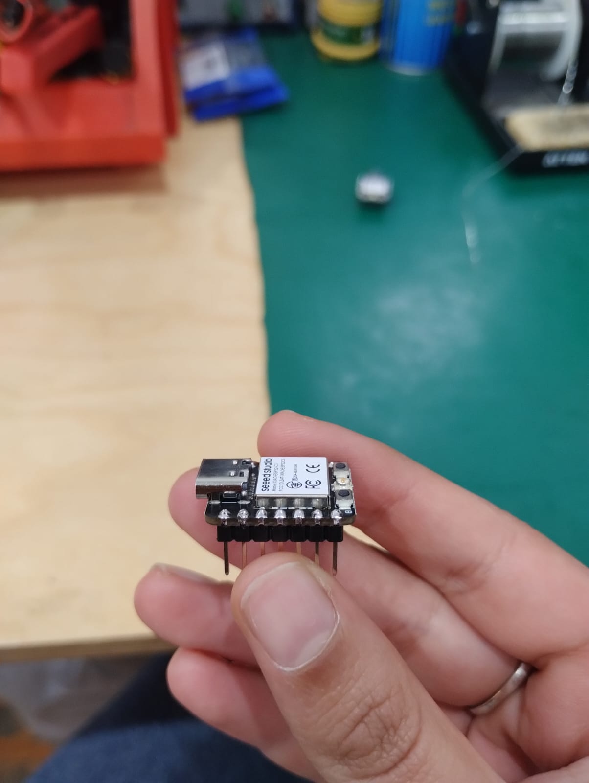
3. ESP32-C3
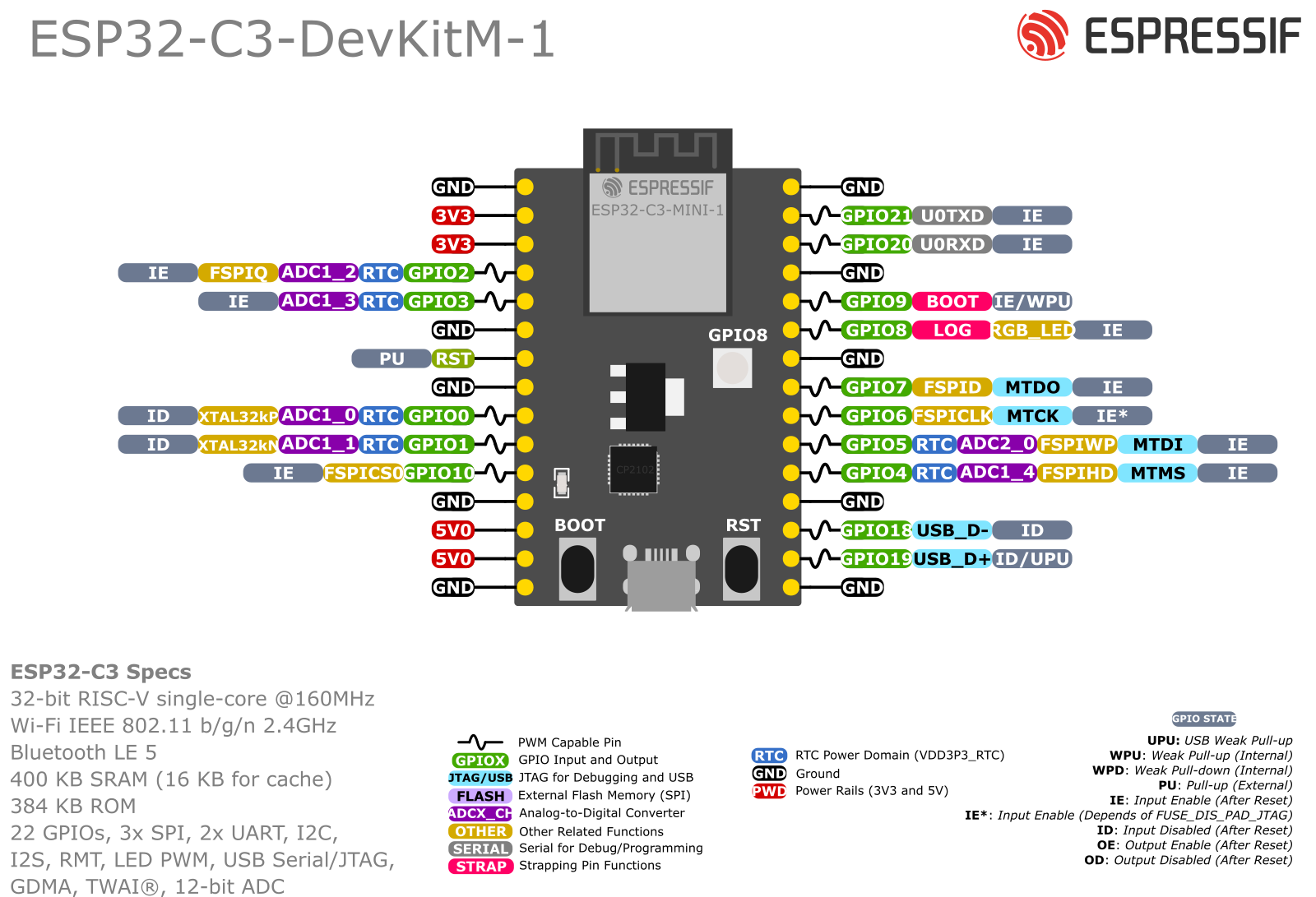
I walked through the datasheet of the ESP32-C3 provided by Espressif. Then followed our instructor Saeed to connect it with Arduino IDE and ran the basic code of blinking to test it's working. Later we tried a code for Rolling Dice on a Led Matrix that I'll mention in the extras section.
2) Individual Assignment
For this week assignment I wanted to get prepared for my final project. As I'm considered a beginner in coding and embedded programming I needed to take it step by step and start by getting to know the soil moisture sensor. I also always wanted to try the OLED so I thought I could add it to my project to show the readings of the sensor and maybe other stuff too.
TBH I had many big dreams for this assignment, waaaaay bigger than I can do in less than a week with my programming skills 😅. I ran to many errors and oled failure and code not working as I want it to do. So, I simplified the code as much as I could to make things work and took it easy on myself 😅.
I need to give a lot of credits to my instructor Saeed and my colleague Amr as they helped me a lot with the code and making things work.
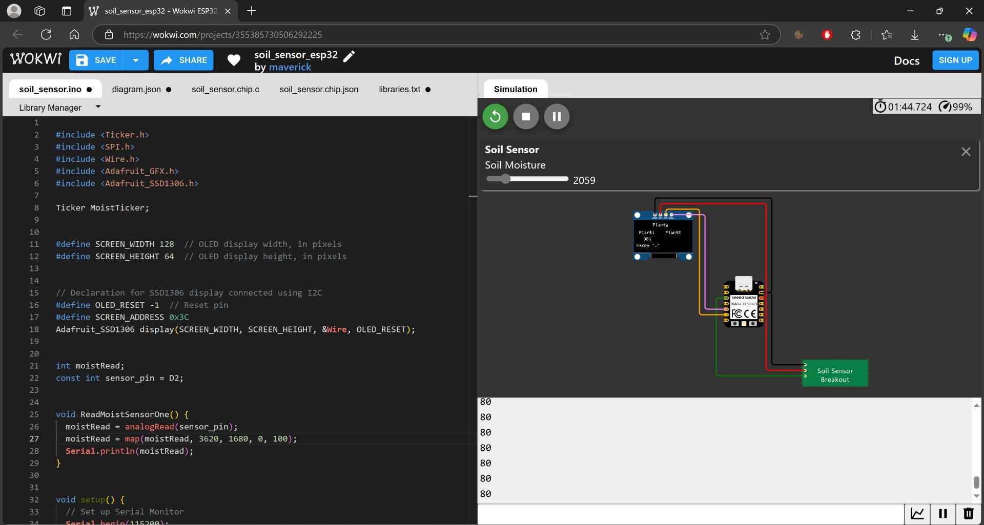
1. Soil Moisture Sensor on OLED Simulation
For this step I used Wokwi to simulate the code running on the components. First, let's know the components I used:
If you click on each component you'll find the websites I used to know more about each one of them like how to connect them to my board and how they work. I couldn't find the soil moisture sensor on wokwi directly so I searched on google writing Soil Moisture Sensor on Wokwi and I found many projects using it and Here is the one I used.
I pasted the XIAO ESP32-C3 from another project on wokwi and added the oled using the plus button then started wiring them together. I also needed to install the project libraries used in the library manager. I then pasted the code I wrote on Arduino IDE and clicked the play button to start simulation.
2. Wiring:
- Soil Moisture Sensor with XIAO ESP32-C3:
-
- GND --> GND
- VCC --> 3.3V
- A0 ---> D2
- OLED with XIAO ESP32-C3:
-
- GND --> GND
- VCC --> 3.3V
- SCL --> D5
- SDA --> D4
3. Coding:
#include < Ticker.h>
#include < SPI.h>
#include < Wire.h>
#include < Adafruit_GFX.h>
#include < Adafruit_SSD1306.h>

Ticker MoistTicker;


#define SCREEN_WIDTH 128  // OLED display width, in pixels
#define SCREEN_HEIGHT 64  // OLED display height, in pixels


// Declaration for SSD1306 display connected using I2C
#define OLED_RESET -1  // Reset pin
#define SCREEN_ADDRESS 0x3C
Adafruit_SSD1306 display(SCREEN_WIDTH, SCREEN_HEIGHT, &Wire, OLED_RESET);


int moistRead;
const int sensor_pin = D2;


void ReadMoistSensorOne() {
	moistRead = analogRead(sensor_pin);
	moistRead = map(moistRead, 3620, 1680, 0, 100);
	Serial.println(moistRead);
}


void setup() {
	// Set up Serial Monitor
	Serial.begin(115200);
	if (!display.begin(SSD1306_SWITCHCAPVCC, SCREEN_ADDRESS)) {
	Serial.println(F("SSD1306 allocation failed"));
	for (;;)
		;  // Don't proceed, loop forever
	}
	display.clearDisplay();
	MoistTicker.attach(3, ReadMoistSensorOne);
	pinMode(sensor_pin, INPUT);
}

void loop() {
	// Main structure
	display.setTextSize(1);
	display.setTextColor(WHITE);
	display.setCursor(40, 2);
	display.println("Planty");
	display.display();

	display.setTextSize(1);
	display.setTextColor(WHITE);
	display.setCursor(2, 20);
	display.println(" Plant1");
	display.display();

	display.setTextSize(1);
	display.setTextColor(WHITE);
	display.setCursor(70, 20);
	display.println("Plant2");
	display.display();


	//Plant 1 Readings
	if (moistRead > 40) {
	display.setTextSize(1);
	display.setTextColor(WHITE, BLACK);
	display.setCursor(12, 35);
	if (moistRead < 100) display.print(" ");
	if (moistRead < 10) display.print(" ");
	display.print(moistRead);
	display.print("%");
	display.display();

	display.setTextSize(1);
	display.setTextColor(WHITE, BLACK);
	display.setCursor(2, 50);
	display.println("Happy ^_^");
	display.display();

	} else {
	display.setTextSize(1);
	display.setTextColor(WHITE, BLACK);
	display.setCursor(12, 35);
	if (moistRead < 100) display.print(" ");
	if (moistRead < 10) display.print(" ");
	display.print(moistRead);
	display.print("%");
	display.display();

	display.setTextSize(1);
	display.setTextColor(WHITE, BLACK);
	display.setCursor(2, 50);
	display.println("SAD :(   ");
	display.display();
	}
	delay(1000);
}
To write this code I combined many codes together and tested many codes first for each module then started editing the code to do what I need it to do. My advice would be to start by testing each module separately and make sure it works then save it in a separate file then start combining all of them together.
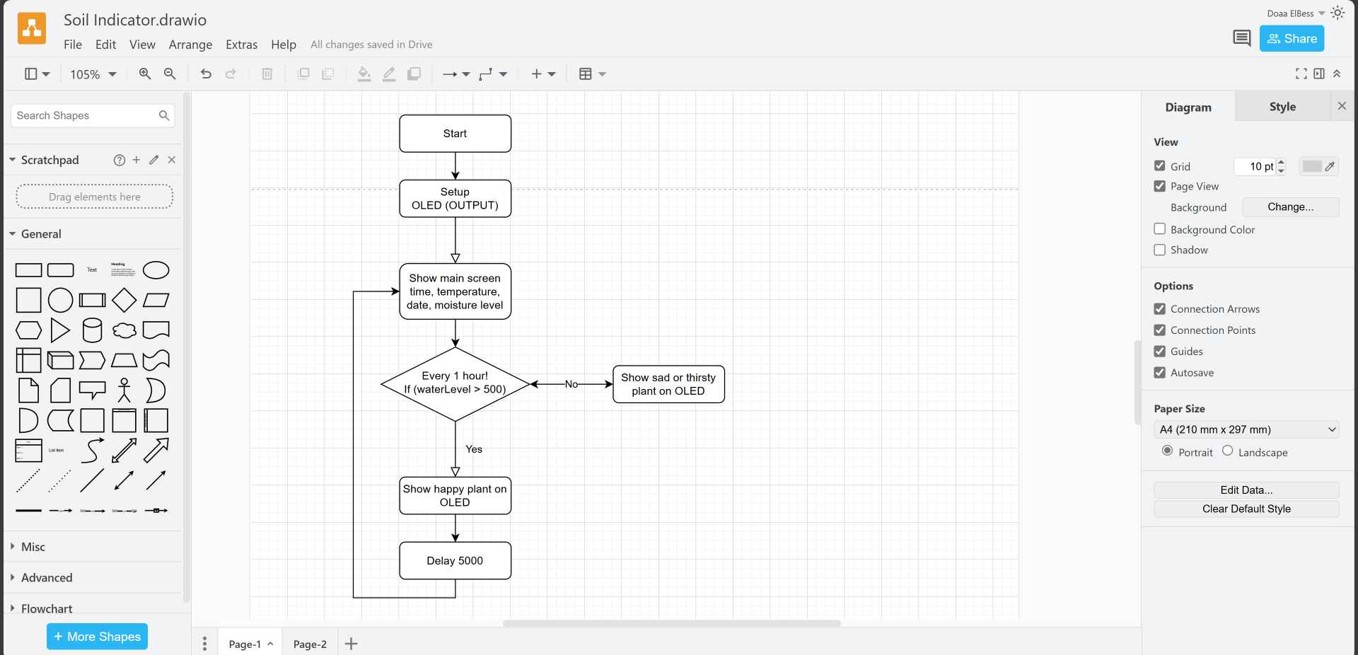
I've tried using Draw.io to visualize the sequence of the code using flowchart. What I ended up making was that when there are main words will be always shown on the display like planty and plant1. And I used Ticker library and function to repeat an action which is getting the sensor reading every one hour for example without interfering with the main loop. And in the void loop it will see if the reading is more than 40%, it'll show the precentage and a happy word ^_^ , else, it will show the precentage and a sad word :(.
// The OLED Code

#include < SPI.h>
#include < Wire.h>
#include < Adafruit_GFX.h>
#include < Adafruit_SSD1306.h>

#define SCREEN_WIDTH 128 // OLED display width, in pixels
#define SCREEN_HEIGHT 64 // OLED display height, in pixels

// Declaration for SSD1306 display connected using I2C
#define OLED_RESET     -1 // Reset pin
#define SCREEN_ADDRESS 0x3C
Adafruit_SSD1306 display(SCREEN_WIDTH, SCREEN_HEIGHT, &Wire, OLED_RESET);

void setup()
{
  Serial.begin(115200);

  // initialize the OLED object
  if(!display.begin(SSD1306_SWITCHCAPVCC, SCREEN_ADDRESS)) {
    Serial.println(F("SSD1306 allocation failed"));
    for(;;); // Don't proceed, loop forever
  }
  // Clear the buffer.
  display.clearDisplay();
}
This is the main and intial code to make the OLED work. And in the void loop or in another void we generate, we can add what we want to show on the display using the functions needed. I knew them from the link I provided earlier for the OLED and used what I needed.
#include < Ticker.h>

int moistRead;
const int sensor_pin = D2;

void ReadMoistSensorOne() {
	moistRead = analogRead(sensor_pin);
	moistRead = map(moistRead, 3620, 1680, 0, 100);
	Serial.println(moistRead);
}

void setup() {
	MoistTicker.attach(3, ReadMoistSensorOne);
	pinMode(sensor_pin, INPUT);
}

void loop() {
	//Plant 1 Readings
	if (moistRead > 40) {
	display.setTextSize(1);
	display.setTextColor(WHITE, BLACK);
	display.setCursor(12, 35);
	if (moistRead < 100) display.print(" ");
	if (moistRead < 10) display.print(" ");
	display.print(moistRead);
	display.print("%");
	display.display();

	display.setTextSize(1);
	display.setTextColor(WHITE, BLACK);
	display.setCursor(2, 50);
	display.println("Happy ^_^");
	display.display();

	} else {
	display.setTextSize(1);
	display.setTextColor(WHITE, BLACK);
	display.setCursor(12, 35);
	if (moistRead < 100) display.print(" ");
	if (moistRead < 10) display.print(" ");
	display.print(moistRead);
	display.print("%");
	display.display();

	display.setTextSize(1);
	display.setTextColor(WHITE, BLACK);
	display.setCursor(2, 50);
	display.println("SAD :(   ");
	display.display();
	}
	delay(1000);
}
And for the Soil Moisture Sensor it was easy to code as I define the sensor pin in global variables which was D2. Also, an int variable to store the analogRead of the sensor in it. And in Void setup I set the pinMode of the sensor pin as an INPUT.
I made the variable moistRead store the data from the sensor reading and made a map for it based on the sensor reading, when it reads 3620, it stores 0, and when it reads 1680, it stores 100. This will be adjusted based on the sensors reading in air and water. as this is the max and min readings of the sensor.
3) Extras:
This week I did a lot of tests and tried different things the biggest of them was testing the code on real board and making 2 boards communicate with each other using ESP-NOW which was totally new topic for me. So, walk with me through my ups and downs in this exciting week 🖤.
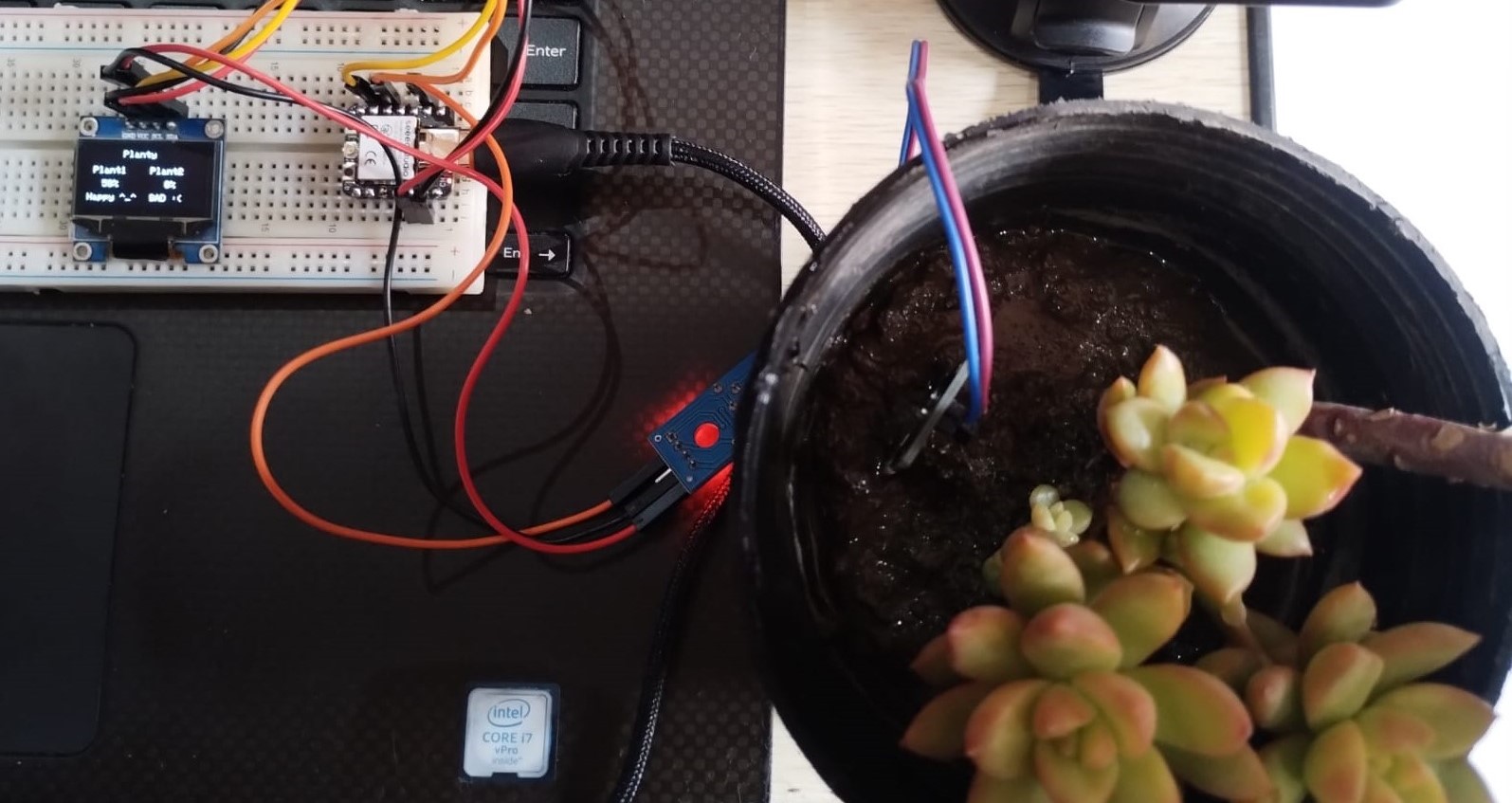
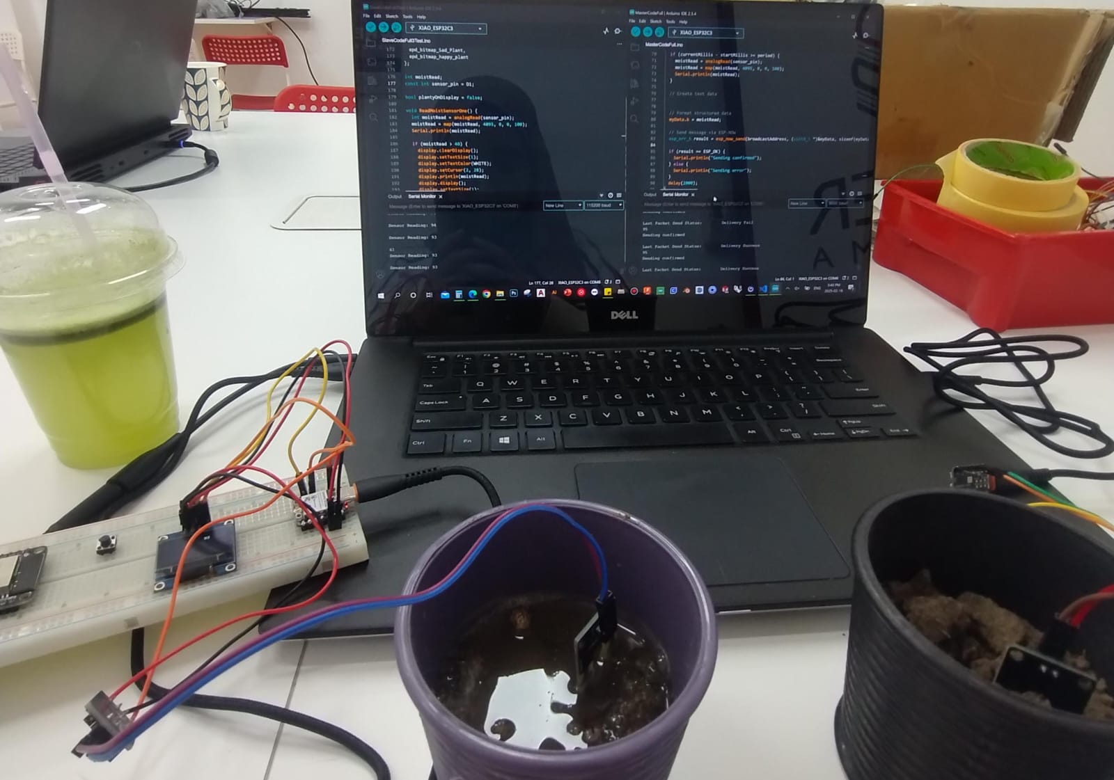
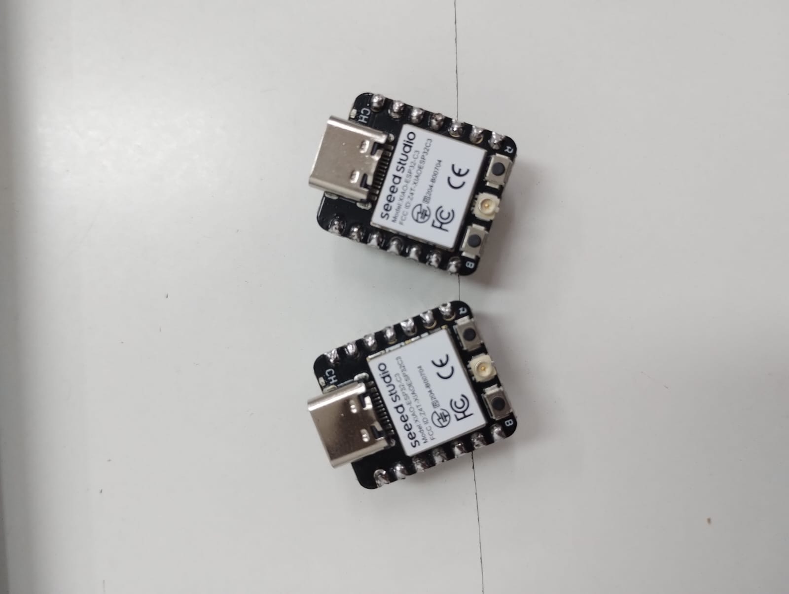
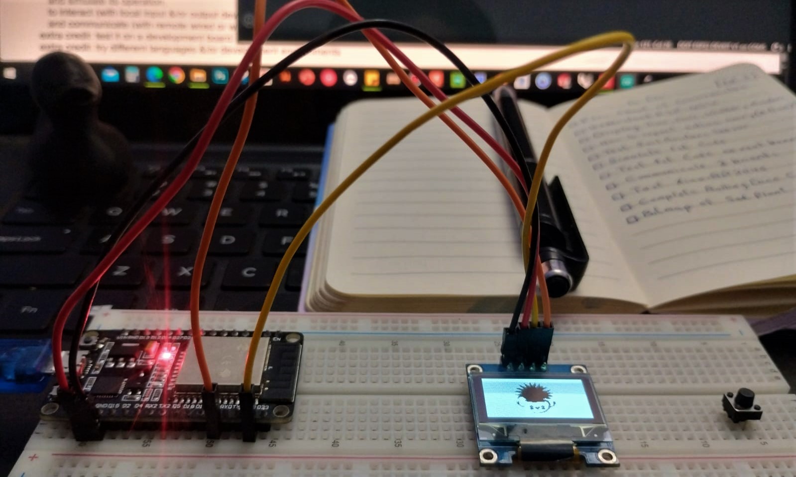
1. Physical Testing on Real Boards:
After making sure everything works perfectly in simulation I wanted to push the limits and test it in real world. I used 2 boards of XIAO ESP32-C3, one with a soil moisture sensor only and the other is connected to another sensor and the OLED. The first board will send the reading of the sensor to the second board using ESP-NOW protocol and display the reading on the OLED. I did this based on Saeed's advice to help me later in modularity and adding more plants to the system.
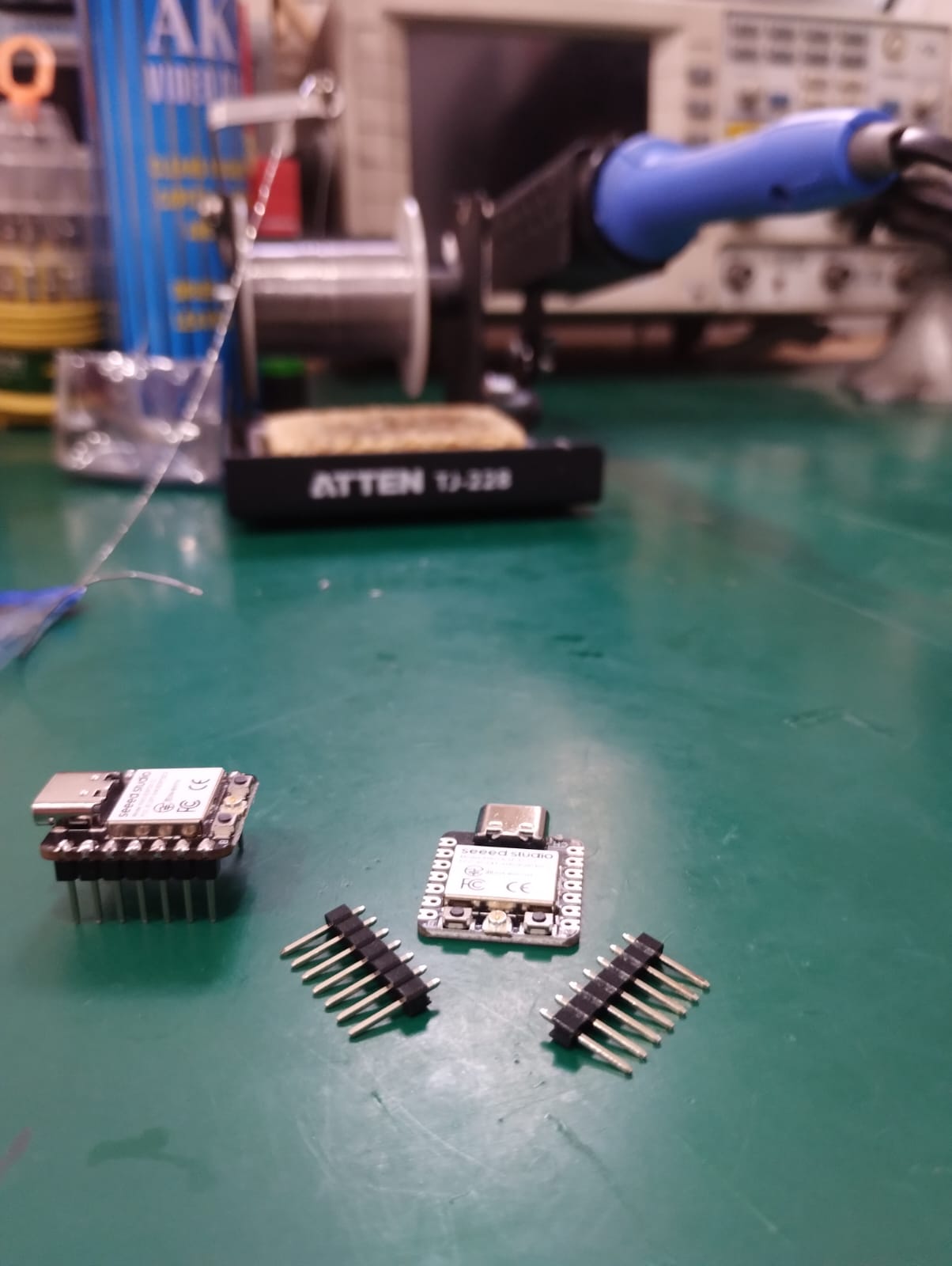
I also had my first boards welding this week and it was really fun. 🖤
2. ESP-NOW Communication:
For understanding this protocol I went through a lot of websites, videos, and even asked ChatGPT but the link which was very helpful for me was sent to me from Amr and saved me. Here it is. He also helped me writing the MAC Address of my reciever ESP and told me that we don't need a code to know the MAC Address, when we run any code using Arduino IDE it shows in the output section 😅.
I used the one way communication code, read and understood it, then changed some lines and data based on my need. The one question I still have regarding to this protocol is would it conflict with the wifi if I wanted to use it for NTP Server for example?
3. Testing components and codes:
Before the final result I had many tests on my components. For example, I've tried to show a bitmap image on the OLED using Image2cpp. First, I downloaded an image for a happy and a sad plant then imported them to Inkscape and put them in a page size of 128x64 px to fit the OLED screen then imported the images from inkscape to the site. You'll find all steps in the OLED site.
I also had to calibrate the soil moisture sensor by putting them in air and in water, in dry soil and in wet soil to see their readings and help mapping the readings. Saeed helped me a lot with this one.
NTP Server: I wanted to test how I could display the date and time on the OLED so I started by exploring NTP Server and tested the code alone with the board and it worked, but when I tried to integrate it with the full code it didn't work I guess because of the ESP-NOW.