
Computer Controlled Cutting
Here's a summary about what you'll see next:
- 1) Group Assignment:
-
- Getting to know about Laser Cutting
- Test Materials Cut Speed and Kerf
- Test T-Slot Joint on Different Materials
- 2) Individual Assignment:
-
- Some Pre-Assignments
- Vinyl Cutting Design
- Jewellery Construction Kit
- 3) Original Files
1) Group Assignment
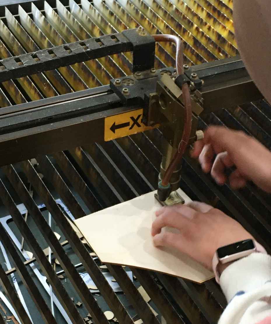
1. Getting to know about Laser Cutting
We started with our instructor Noha Hani Explaining the laser cutting machine we have in Fab Lab Egypt which is El Malky ML149. These numbers mean that the machine workarea is 140 cm * 90 cm. It's a CO2 Laser machine designed and manufactured by El Malky an Egyptian company.
She explained to us what is the focal length of the machine and how to adjust it. Also, she and the whole team explained to me what is a kerf and how to measure it.
Focal Length For our machine, to adjust the focal length we need to put a piece that's about 6mm.
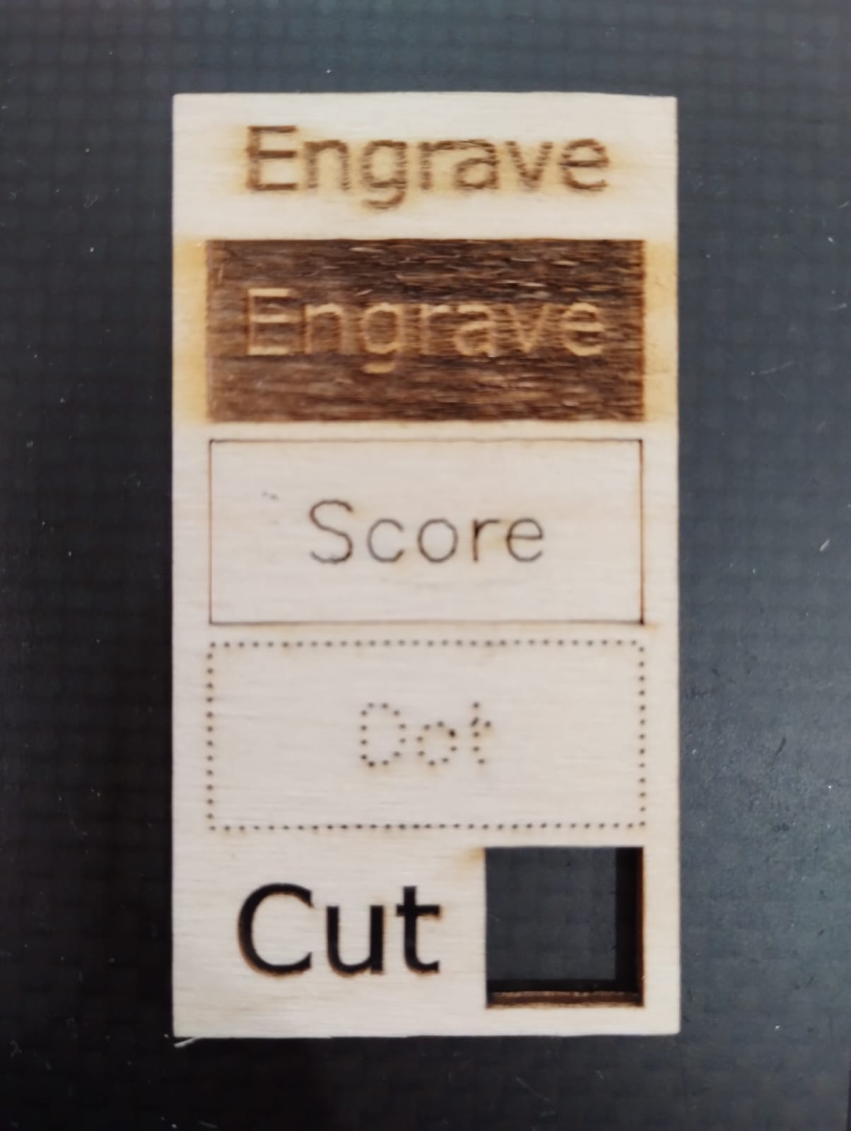
Machine Operations To test what El Malky can do we tested different operations on a 3mm plywood piece.
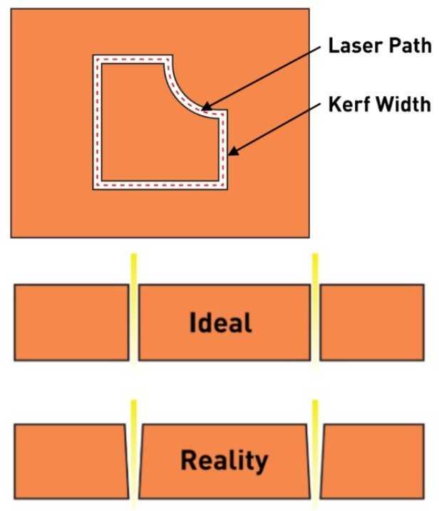
Kerf Simply, we can say that the kerf is the width or thickness of a laser beam. So, for a perfect fit for joints we need to measure and consider it in our design.
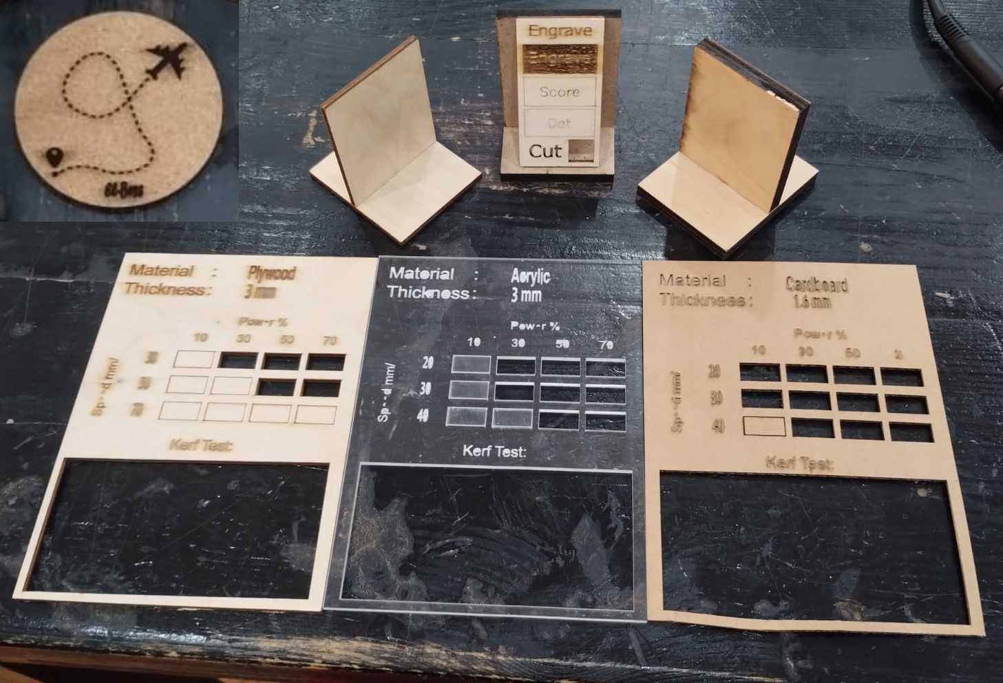
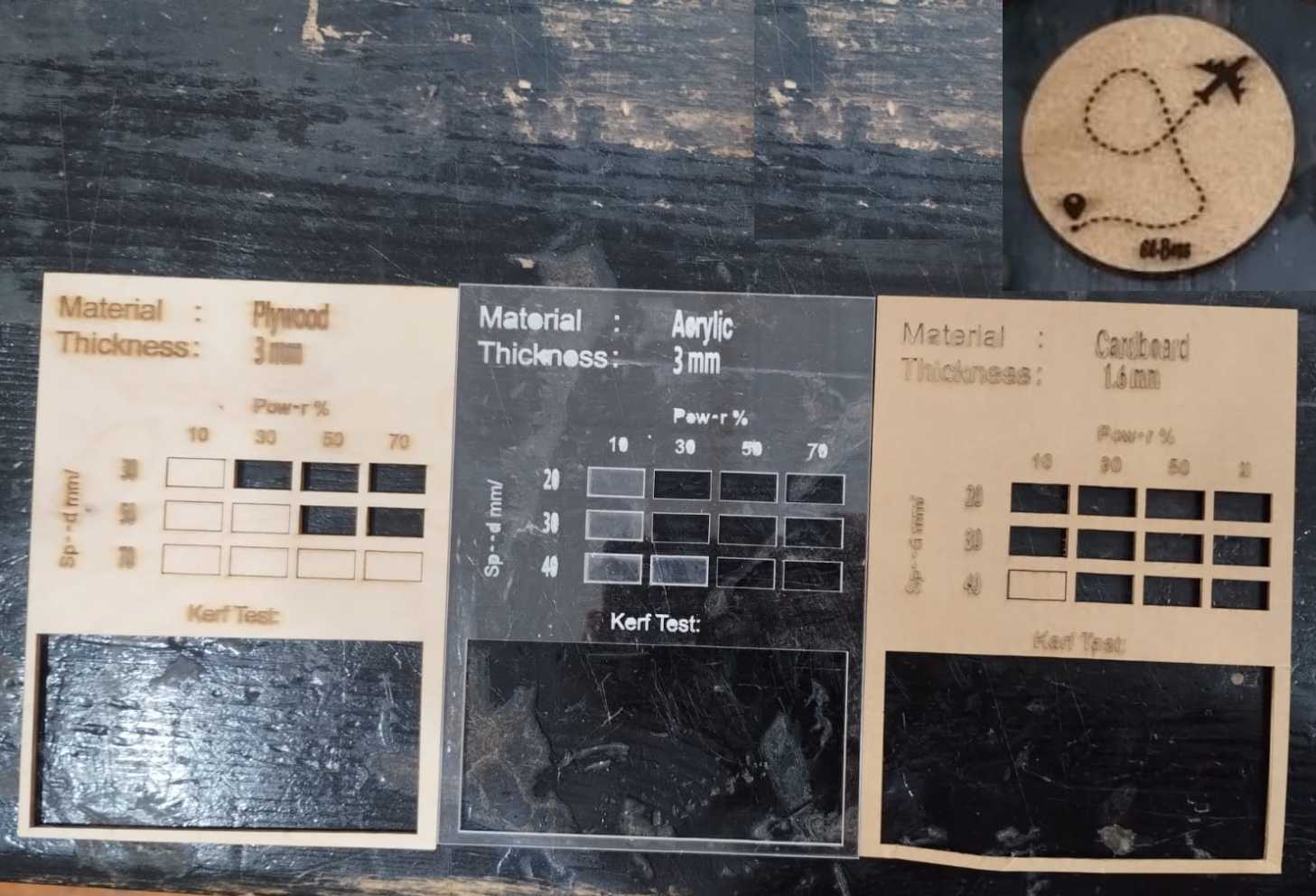
2. Test Materials Cut Speed and Kerf
| Material | Thickness | Cut | Engrave | Kerf |
|---|---|---|---|---|
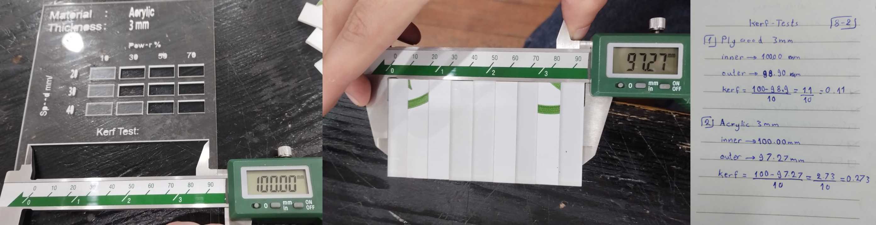
| Plywood | 3mm | Speed: 30Power: 30 | Speed: 300Power: 15 | 0.11 mm |
| Arylic | 3mm | Speed: 20Power: 30 | Speed: 200Power: 15 | 0.273 mm |
| Cardboard | 1.6mm | Speed: 20Power: 10 | Speed: 300Power: 12 | - |
| Cork | 5.7mm | Speed: 50Power: 45 | Speed: 300Power: 20 | - |
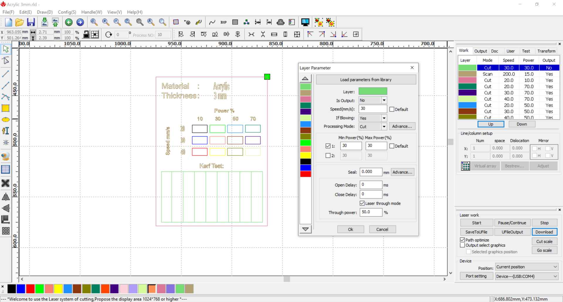
To prepare for testing these materials we downloaded the material test dxf and imported it to RD Works V8. I was familiar with the software before so it was kinda easy to deal with it.
After cutting, we first use the caliber to measure the inner width of the rectangle. Then we measure the width of all the rectangles. We substract these numbers then divide it by 10 "number of lines cut" to get the kerf.
3. Test T-Slot Joint on Different Materials
After each one of us tested different materials and defined their kerfs, it was the time we test diffrnt joints using the kerfs we measured. I worked on the T-Slot joint on plywood 3mm I tested bfore, plywood 6mm which Amr tested, and MDF 5mm which Eman tested. All our measurements worked very fine with the T-Slot and it was perfect joint.
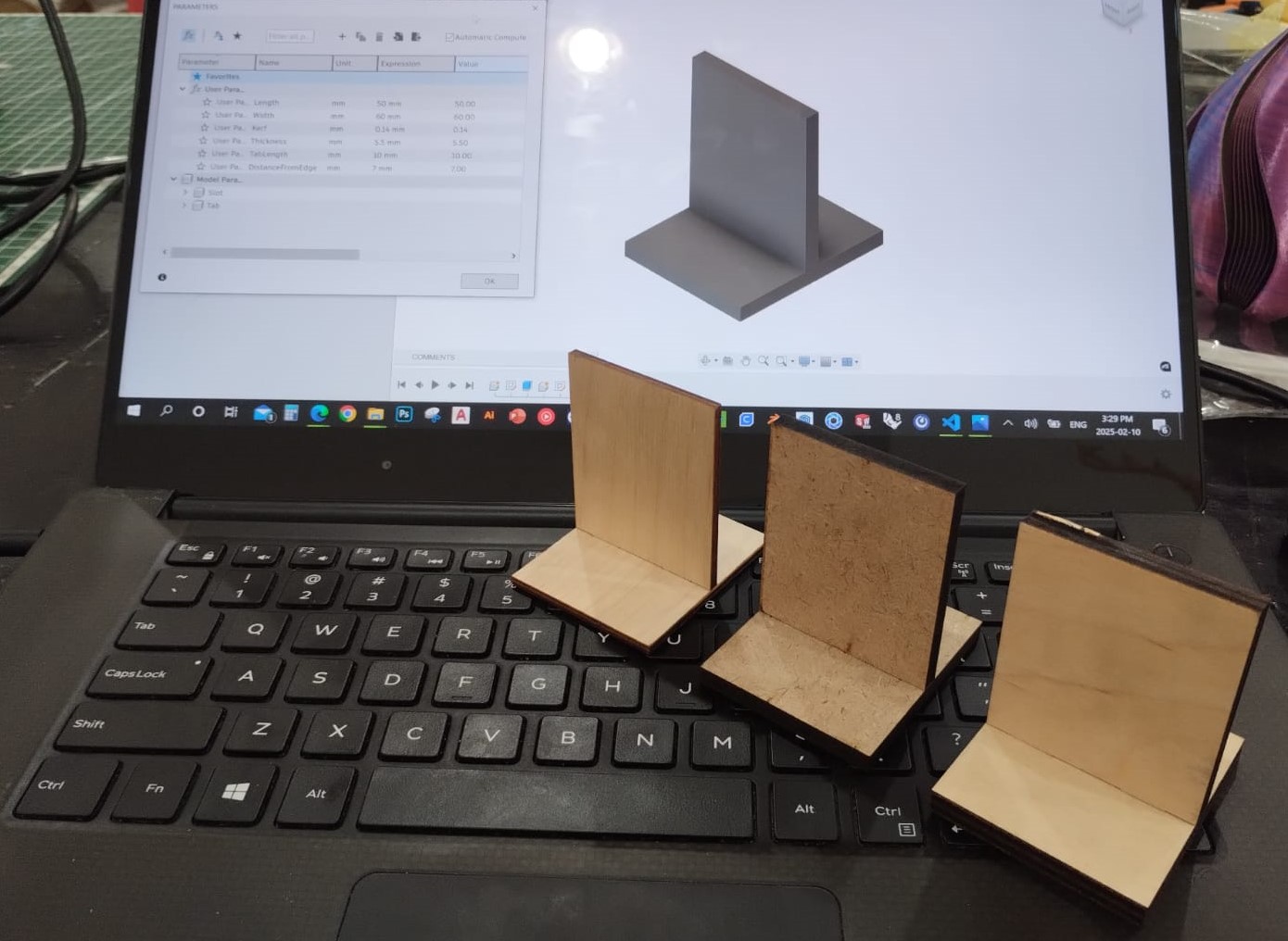
Plywood 3mm Thickness: 2.9mm Kerf: 0.11mm
MDF 5mm Thickness: 5.5mm Kerf: 0.14mm
Plywood 6mm Thickness: 6.68mm Kerf: 0.26mm
2) Individual Assignment
1. Some Pre-Assignments
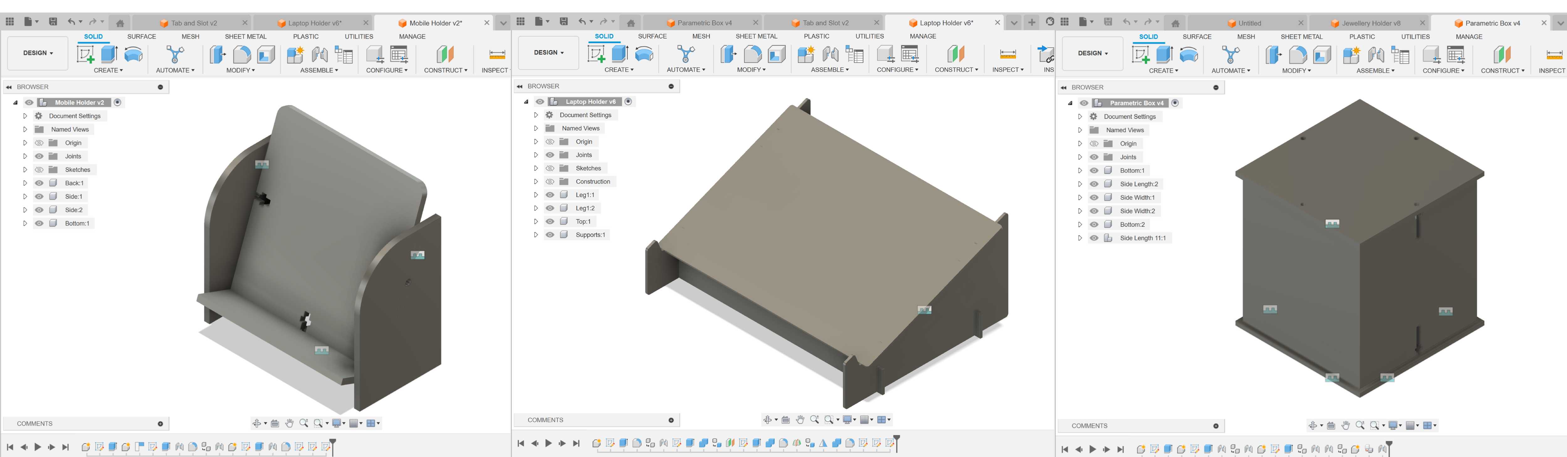
Before starting the individual assignment we went through some pre-assignments to get to know to parametric design. I started at fisrt by following this video of designing a parametric laptop holder. Parametric design meeans that I can bulid the main structure and set some parameters and relations which allow me to change some nubmers later without having to start the design all over again so when I change a parameter the whole design is automatically updated.
I then followed a video making a Mobile Holder using T-slot and captive nut joint. This helped me getting used to make my design organized by creating components for each part and each component has its own sketch.
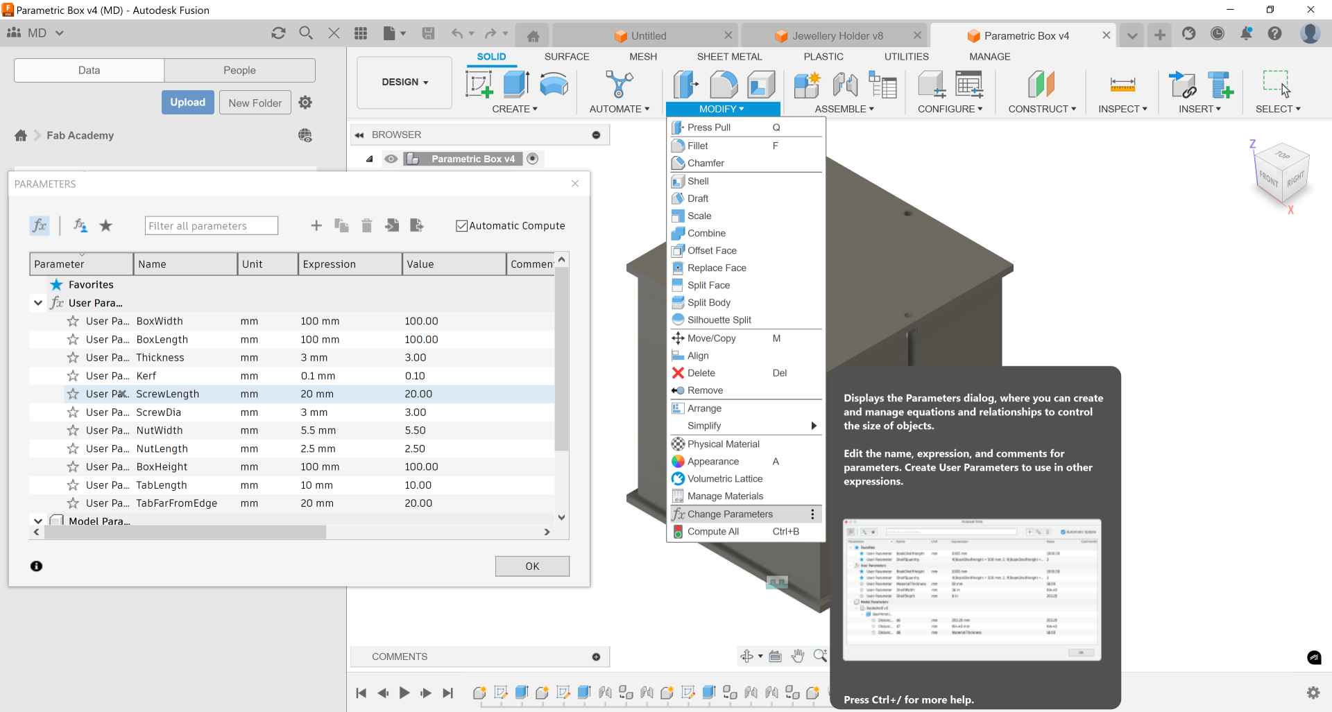
Then I tried to design a parametric box by myself. So, I set these parameters from modify menu then change parameters andd click the + icon to set the parameters I need. And when I make a sketch I can set the dimensions to be equal to the parameters I set before as I write the name of the parameter in the dimension box instead of a number.
2. Vinyl Cutting Design
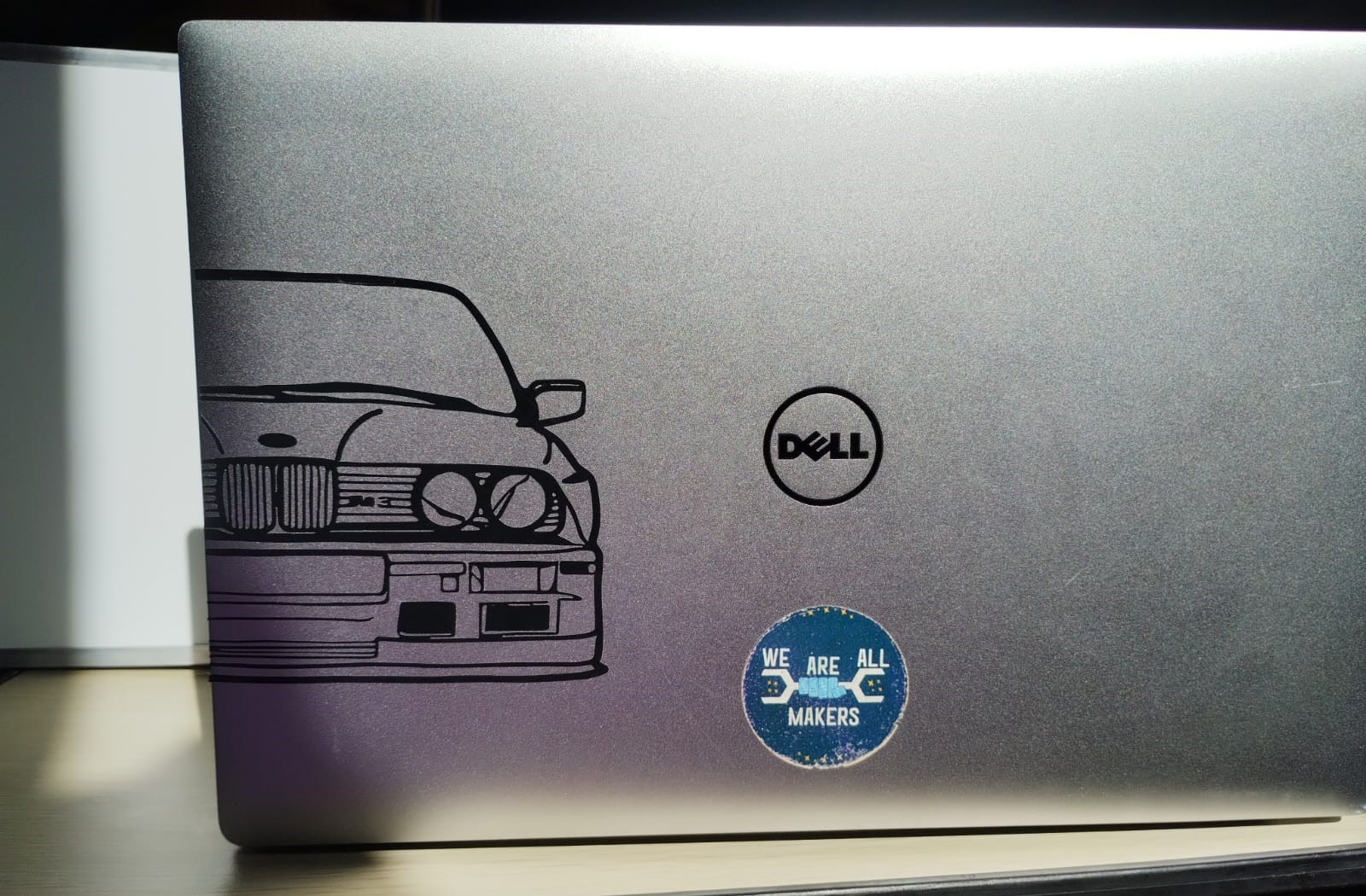
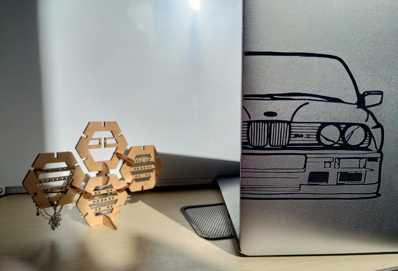
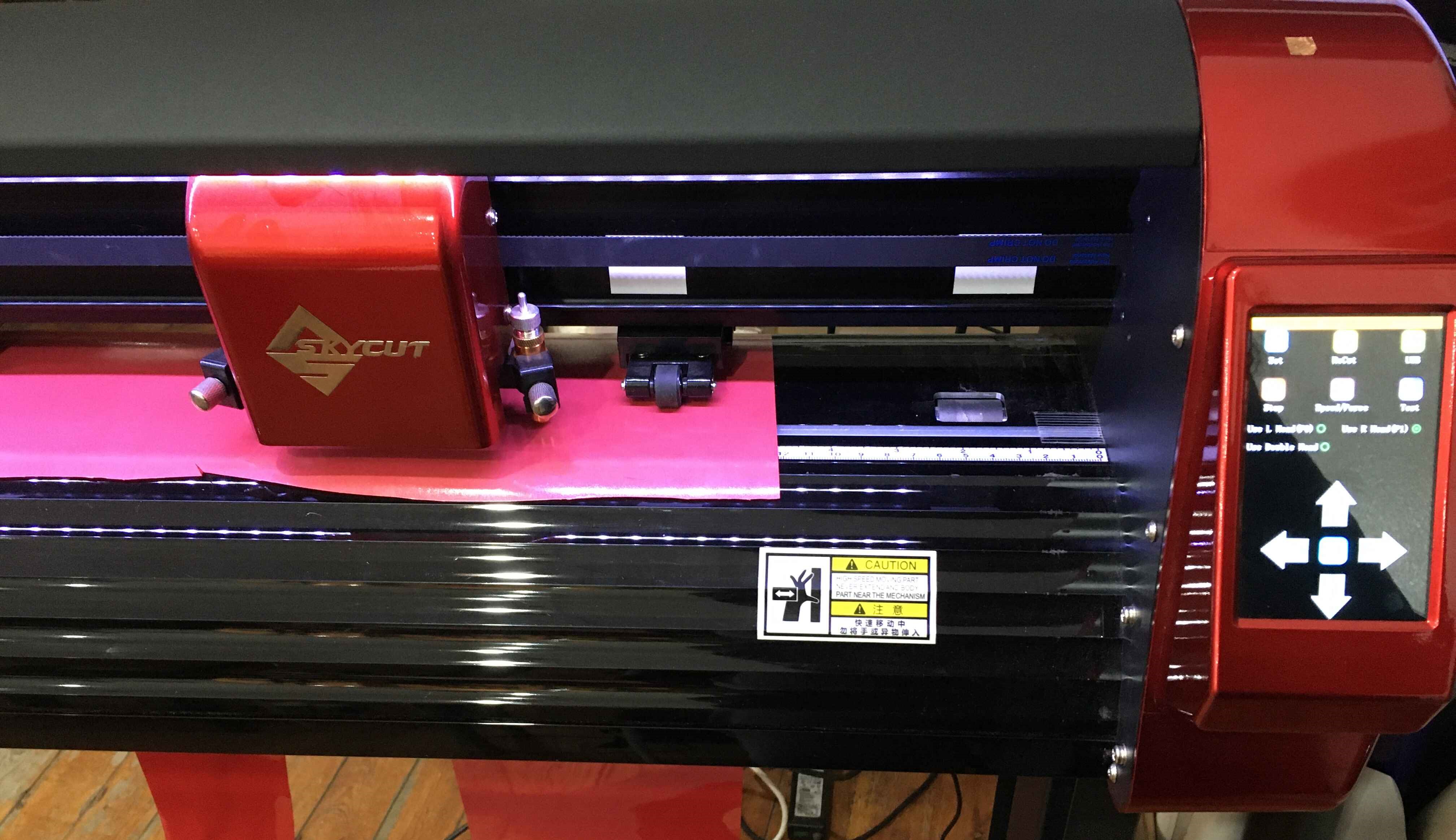
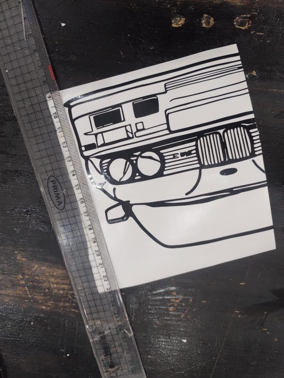
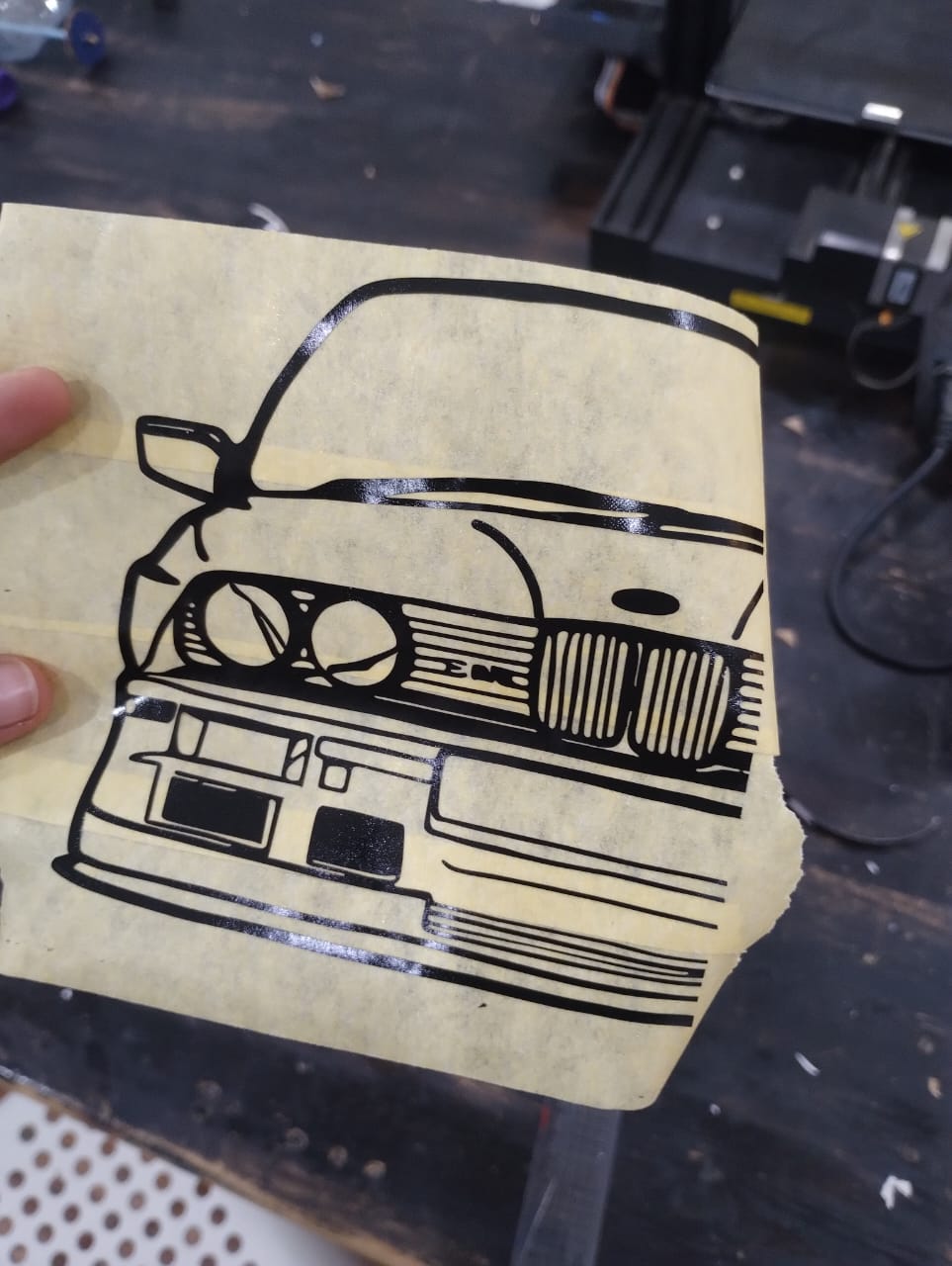
For this assignment I wanted to make a sticker for my laptop. As an obsessed person with cars and specially BMW M3, I decided to make it as a sticker and go through the whole process. I also didn't have previous experience dealing with Vinyl Cutting Machines, so this was a really interesting journey and the hero machine of this assignment is SkyCut D24 Vinyl Cutting Machine.
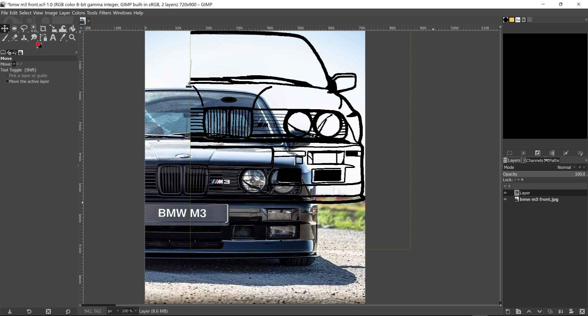
1- I searched for a front view image of the car using google then imported it to GIMP and used the brush tool to track the outline and main lines.
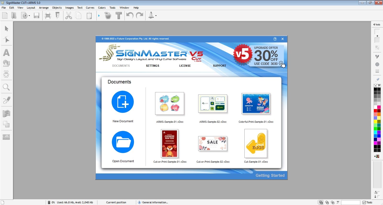
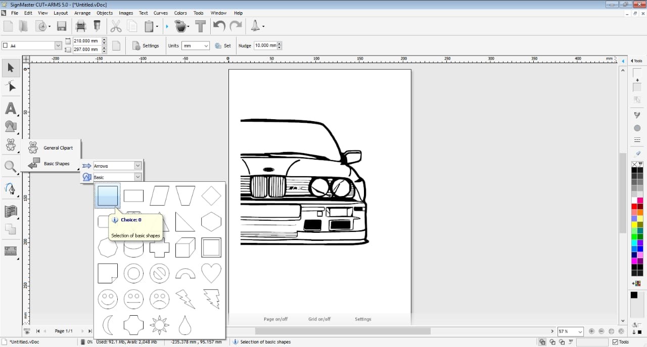
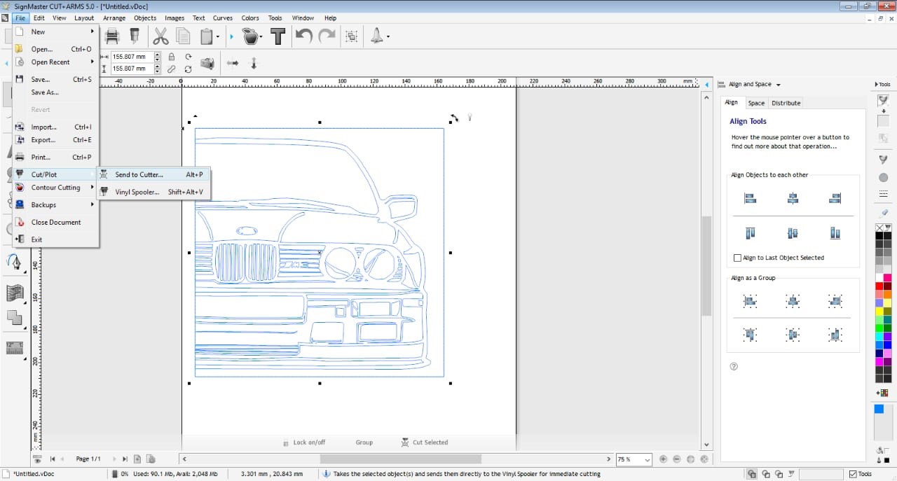
2- I opened the SignMaster program connected to the Skycut vinyl cutter to prepare the sticker for cutting and chose new document.
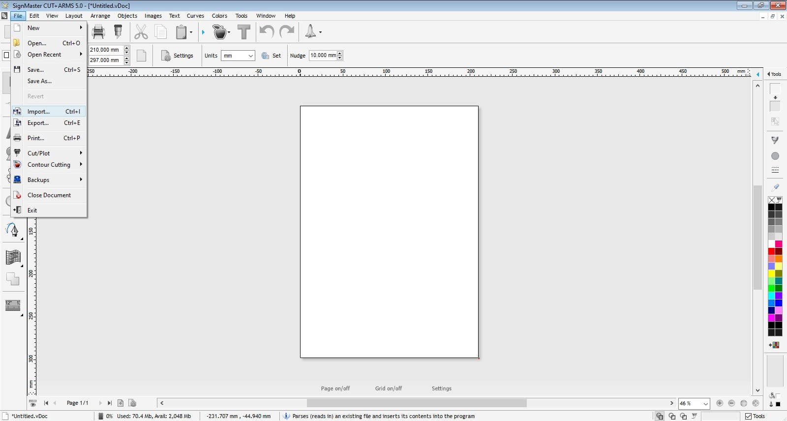
3- From File menu I chose import and imported an svg file of my sticker. It could be jpg also or other formats.
4- I made a rectangle to make a border for the sticker and close the open areas.
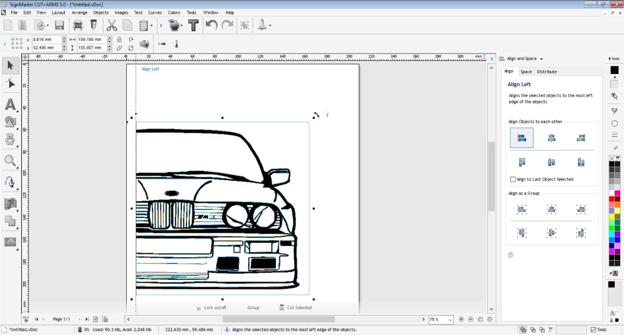
5- From alignment tools I aligned the sticker and the rectangle to the left together.
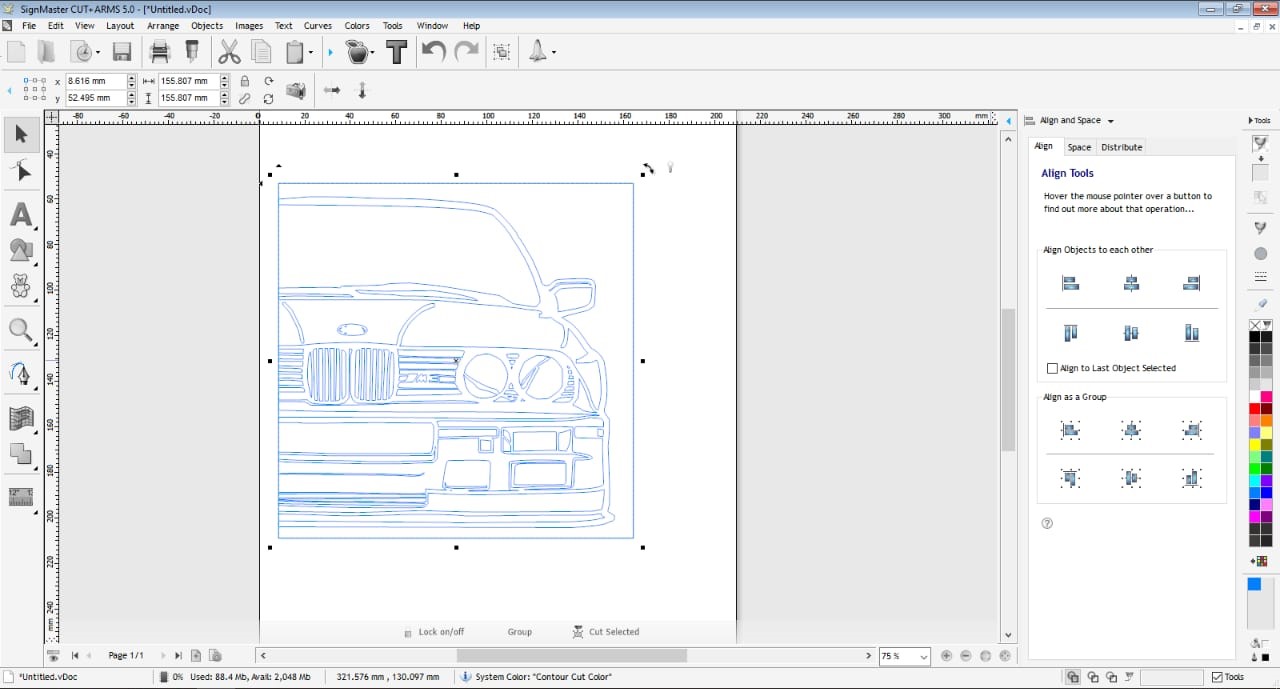
6- In the right where the colors are I made outlines and removed the fill.
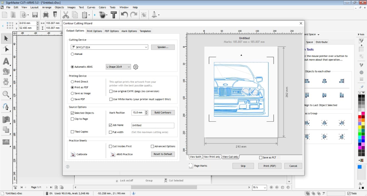
7- From the apple I chose contour cut wizard and selected the machine and we can set more parameters here. Check This link.
8- Now that all things are done we can send the file to the machine.
9- After setting the speed to 250mm/s and force to 12 on the machine it started cutting.
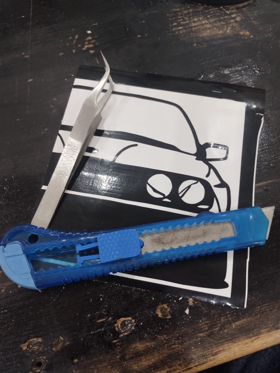
10- Now that the machine is done, it's time for me to work. I used tweezer and cutter to remove unwanted parts carefully as most of them were really small.
11- 3 Million years later 😅 I was able to remove all the unwanted areas.
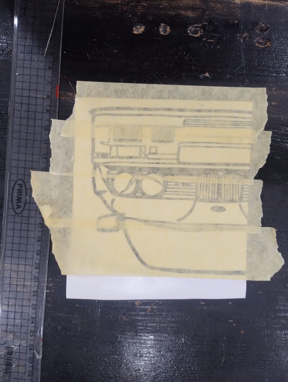
12- To move all the sticker's tiny parts from its place to my laptop I did something called Weeding, which means I place tape on the sticker till I cover it all.
13- Then remove the tape slowly and make sure all the sticker pieces are sticked in place.
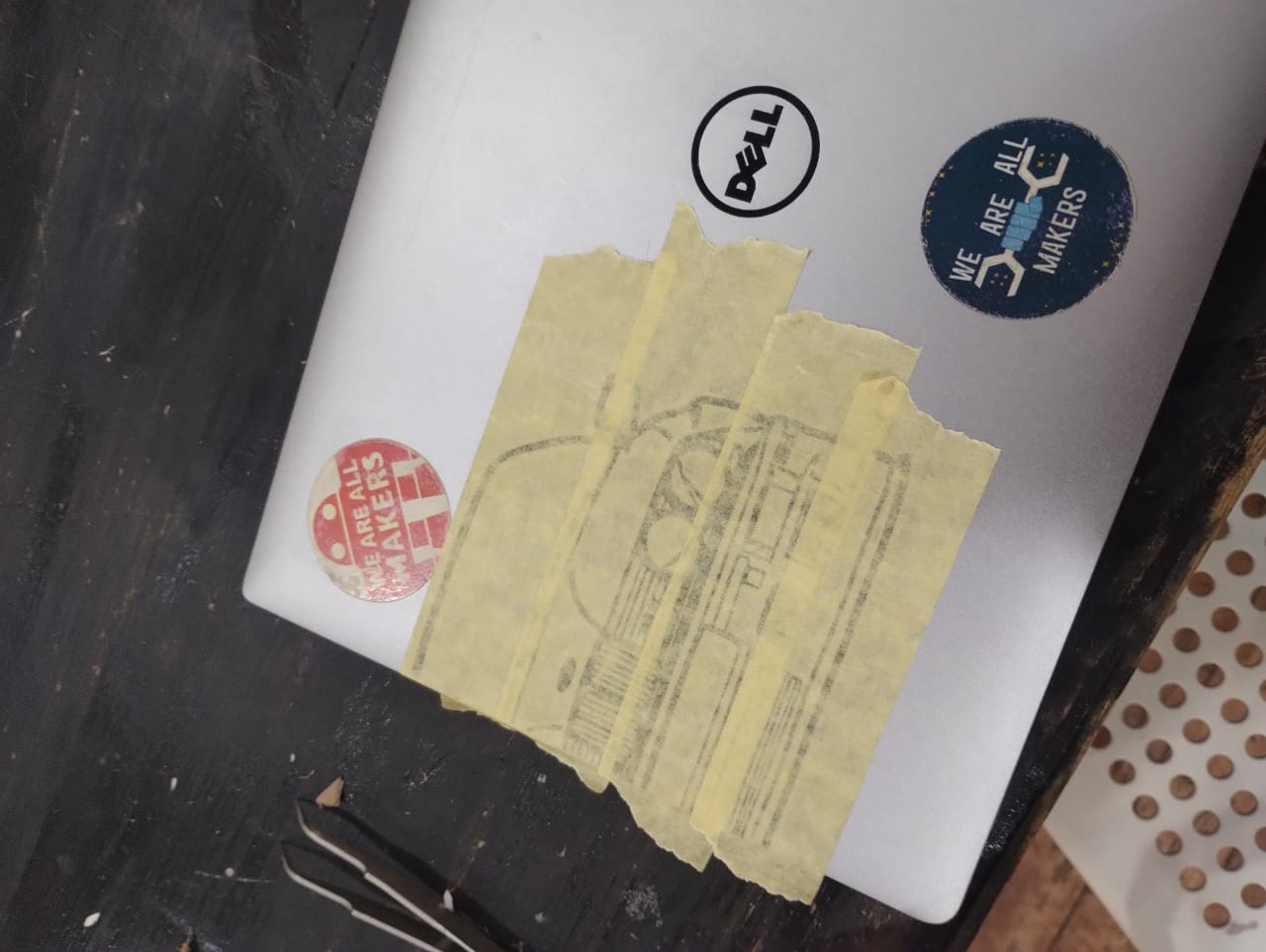
14- I placed the tape carefully on the laptop where I wanted the sticker to be and started removing tape by tape slowly.
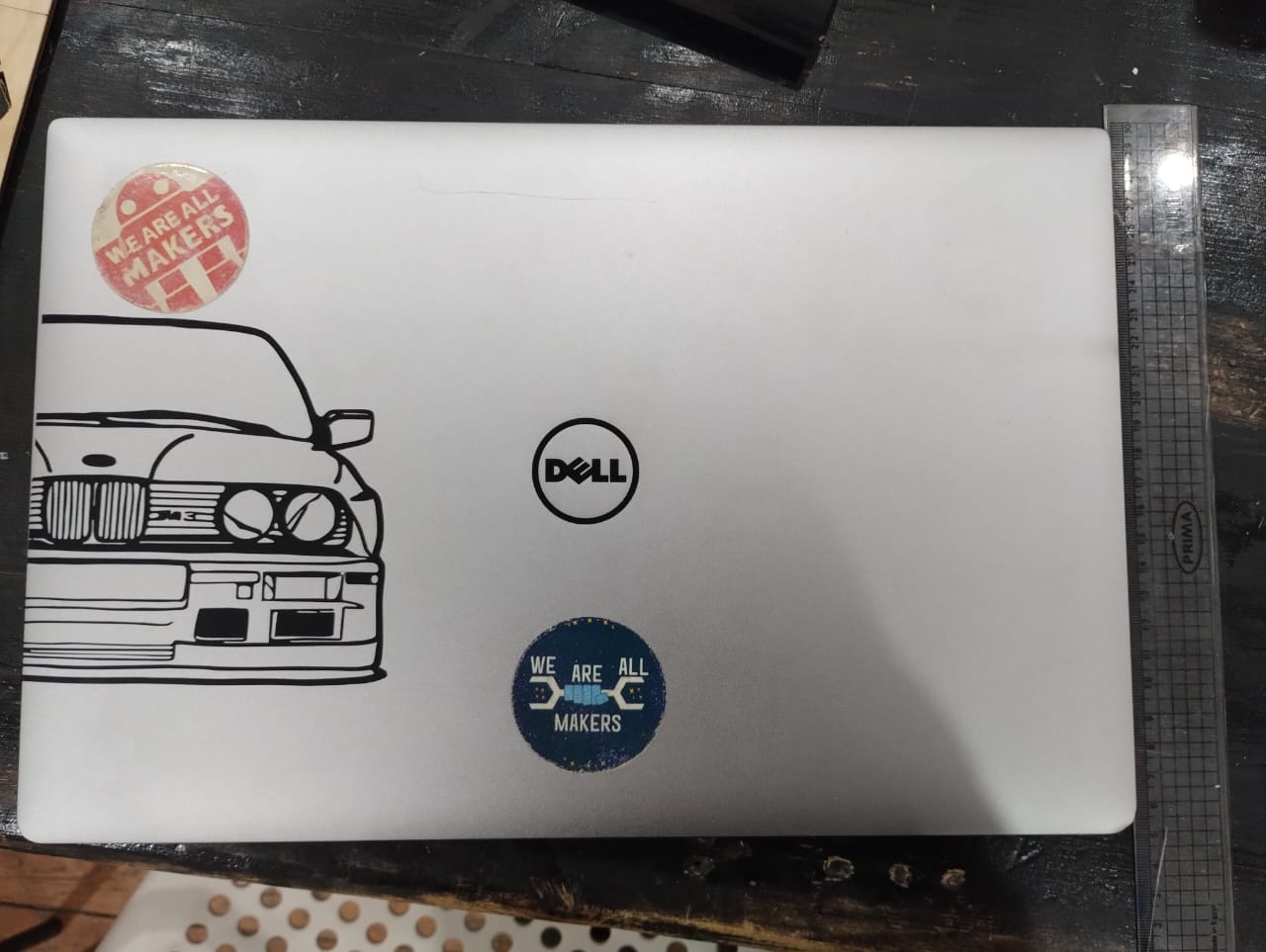
15- Anddd Voilaaaa 🖤.
3. Jewellery Construction Kit
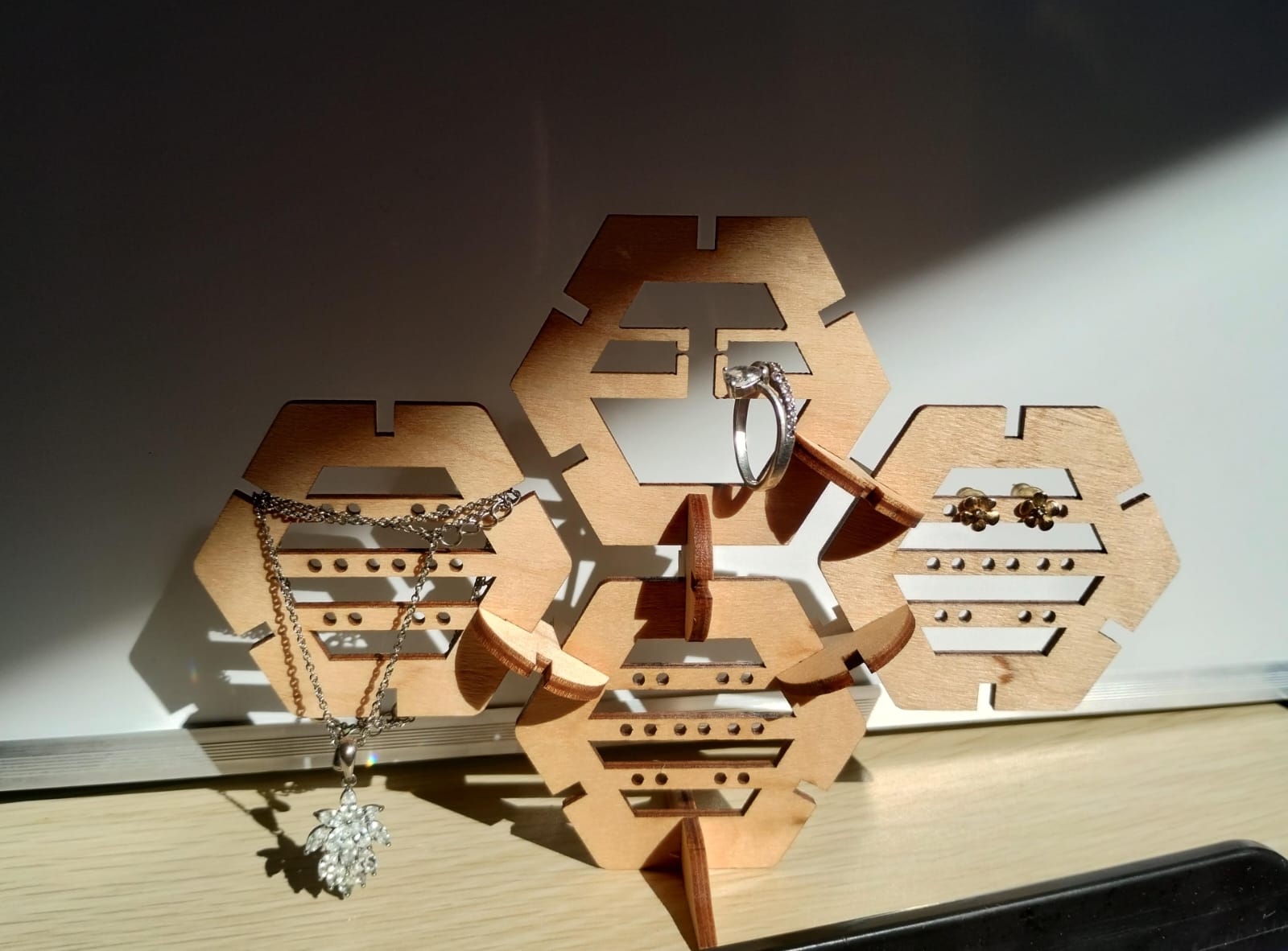
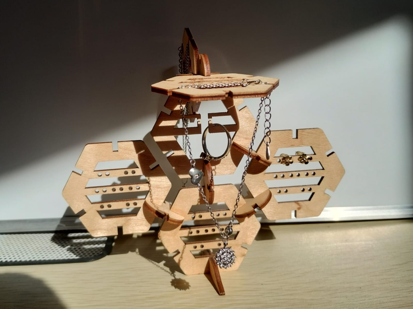
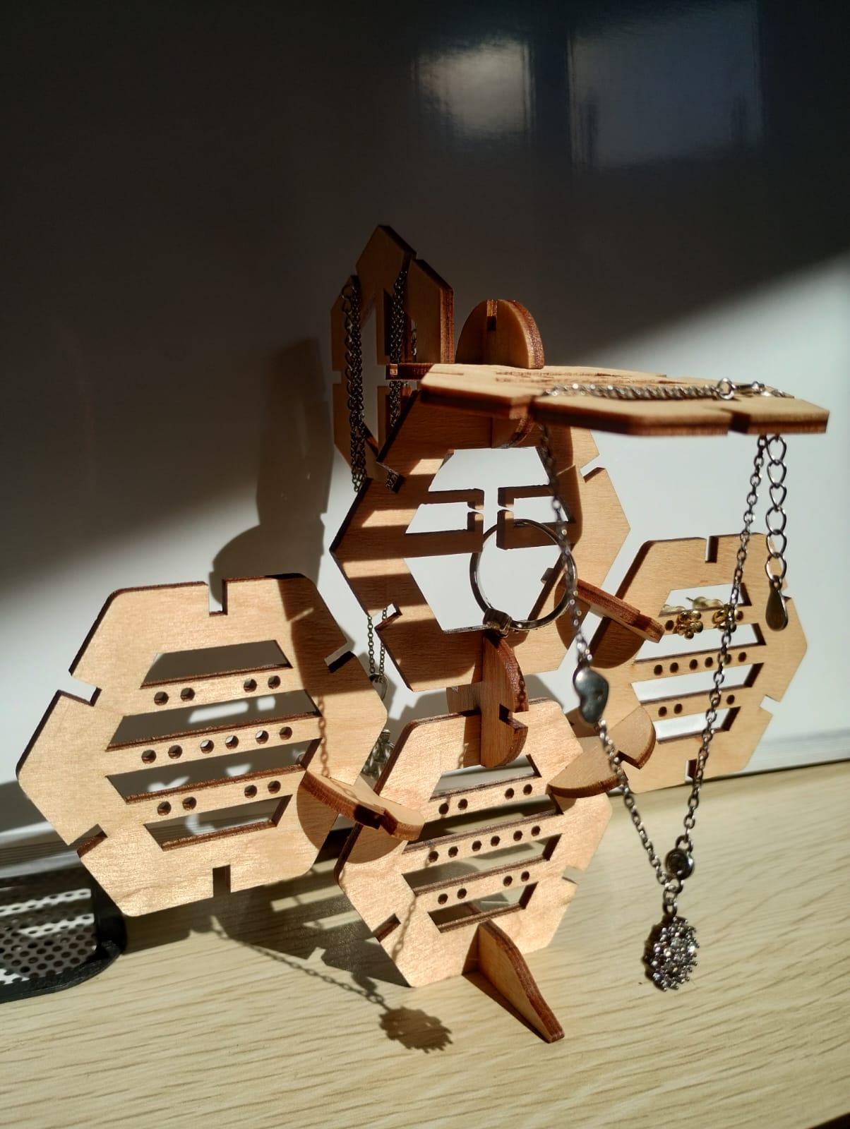
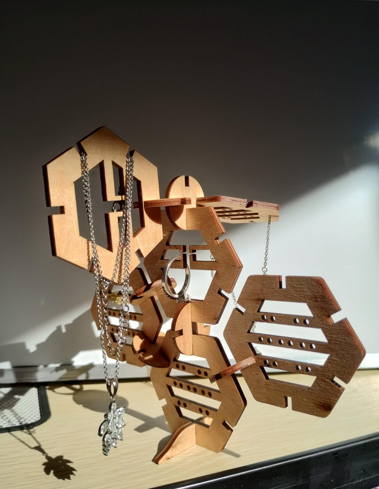
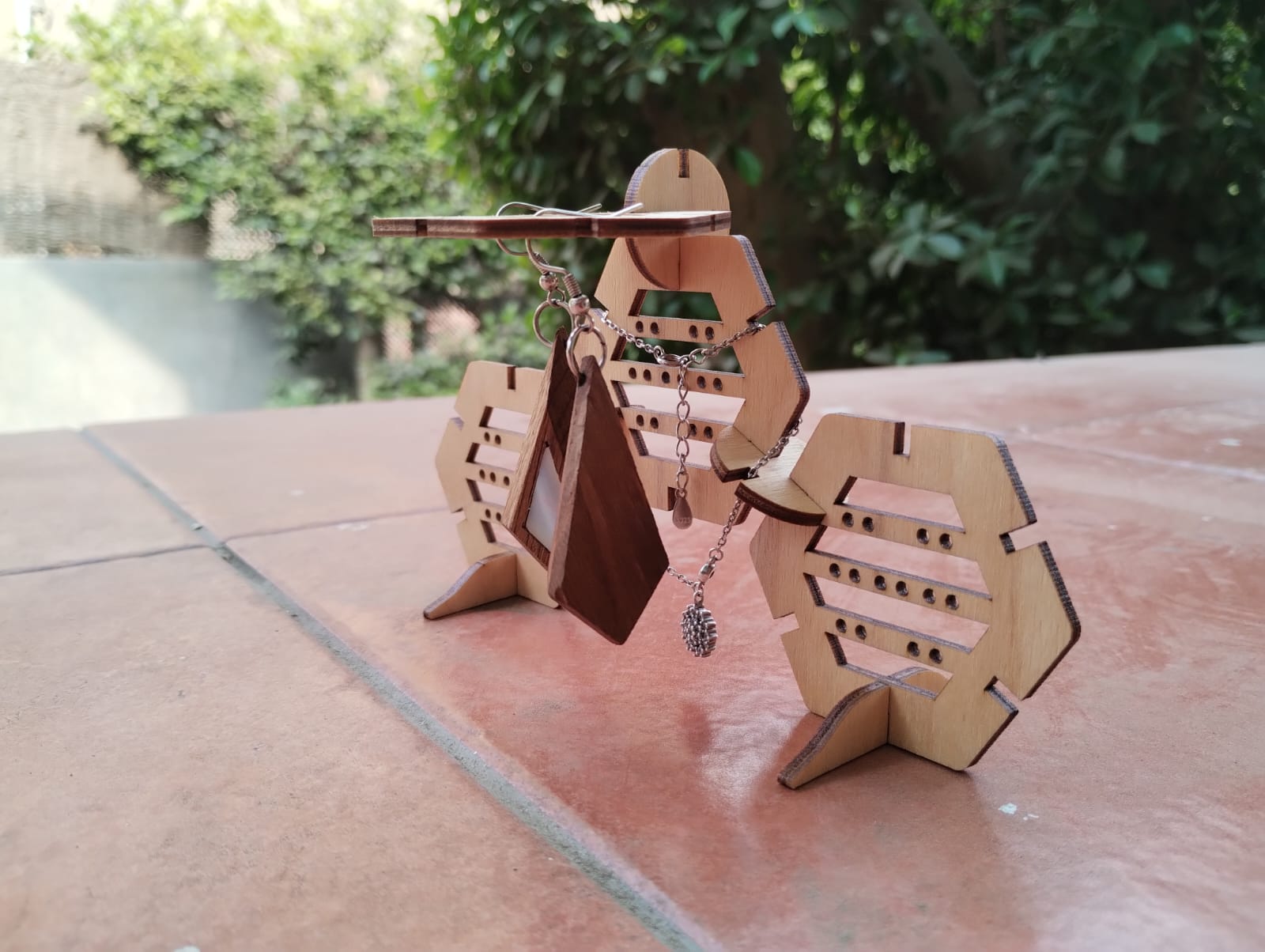
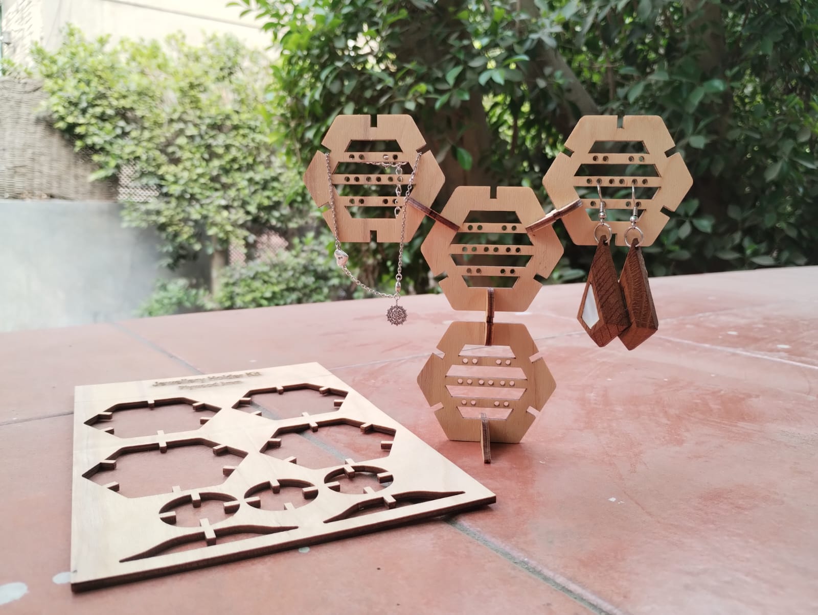
 For this week we needed to "design, lasercut, and document a parametric construction kit,accounting for the lasercutter kerf, which can be assembled in multiple ways".
I searched for ideas using google and pinterest and reviewed previous students work for this week but I wans't able to get to an idea for my construction kit. I sat in the makerspace and started looking around for all the cool stuff around looking for inspiration.
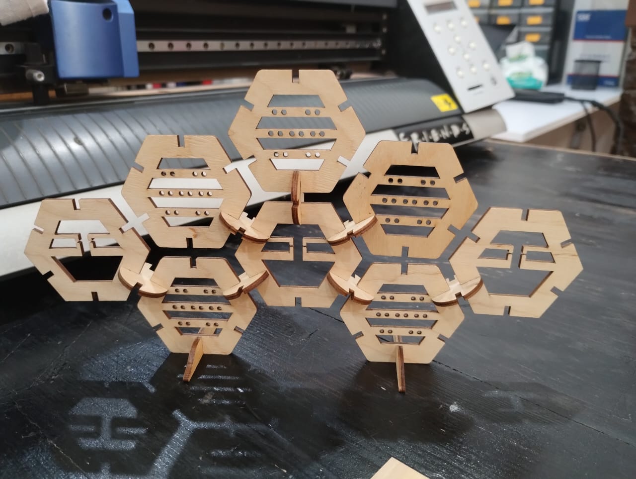
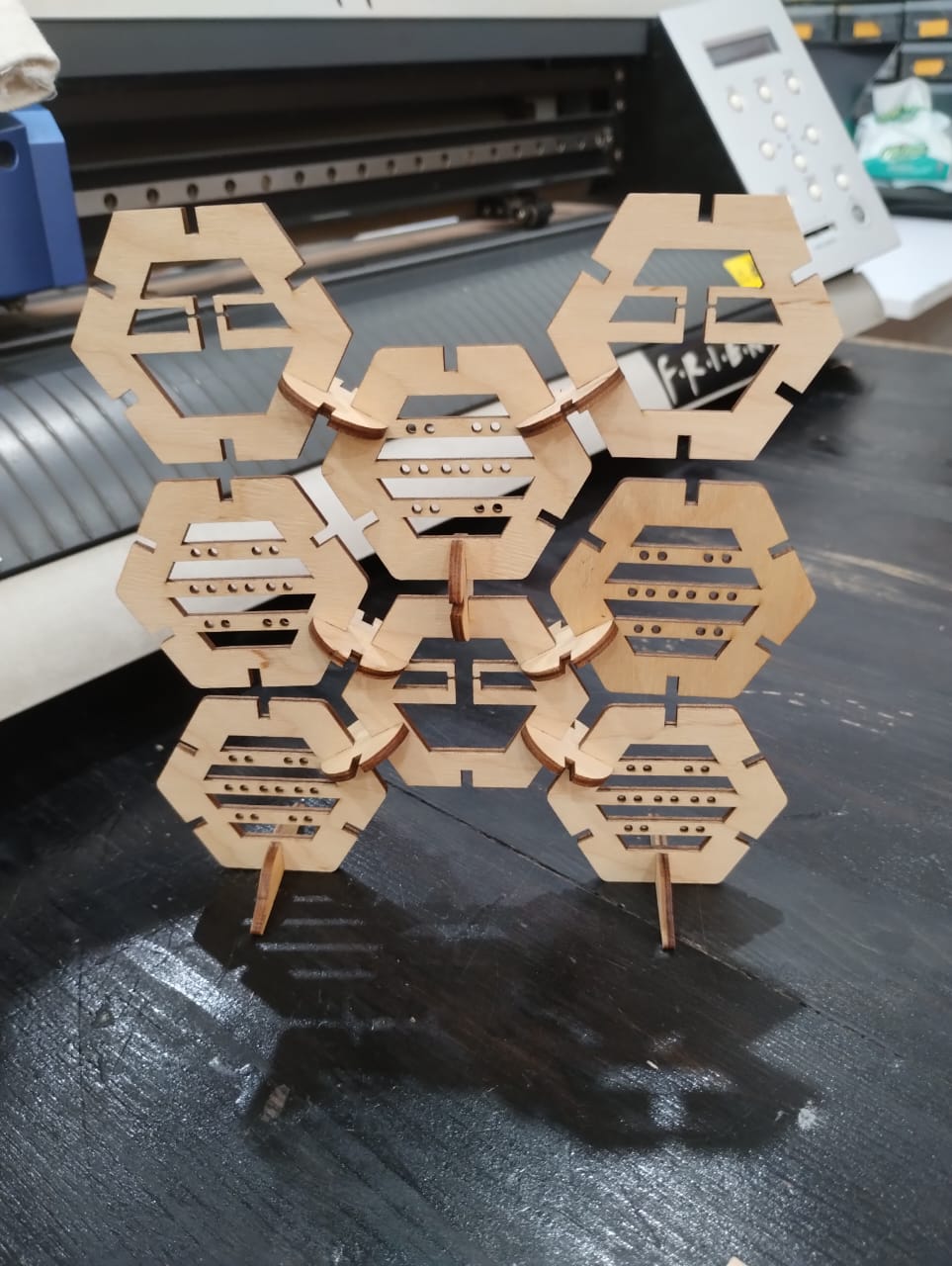
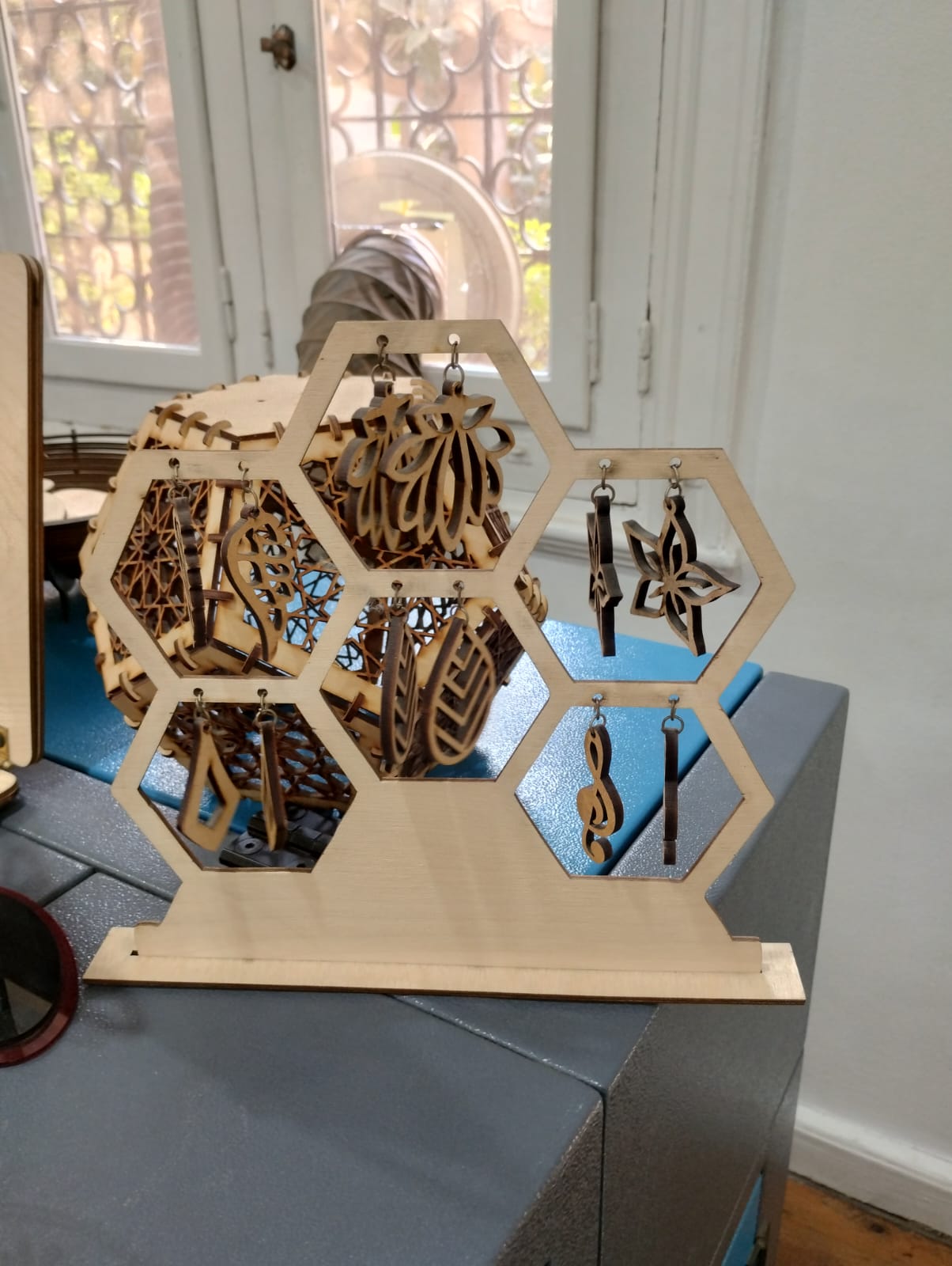
Till I saw this piece 😲 and decided that's ittt. Hxagons are great for making patterns and I will add another piece for connection and another one for support. I searched agian on google for honeycomb jewellery holders and found there were some designs like that but without the ability to shape it in multiple ways.
For this week we needed to "design, lasercut, and document a parametric construction kit,accounting for the lasercutter kerf, which can be assembled in multiple ways".
I searched for ideas using google and pinterest and reviewed previous students work for this week but I wans't able to get to an idea for my construction kit. I sat in the makerspace and started looking around for all the cool stuff around looking for inspiration.
Till I saw this piece 😲 and decided that's ittt. Hxagons are great for making patterns and I will add another piece for connection and another one for support. I searched agian on google for honeycomb jewellery holders and found there were some designs like that but without the ability to shape it in multiple ways.
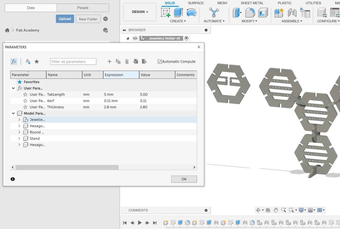
1- I started by setting the parameters for th construction kit and all I really needed was just the kerf and the thickness.
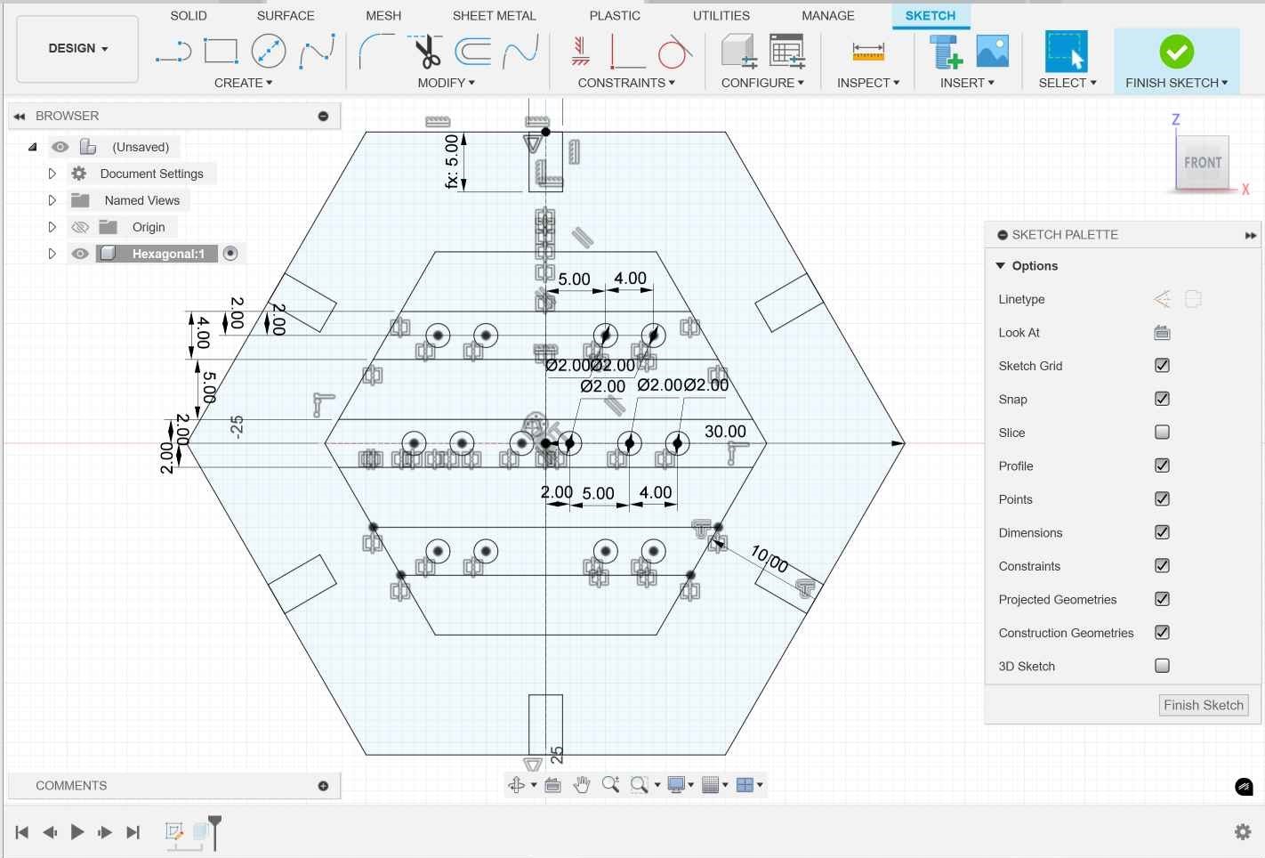
2- I choosed to create new component then sketched the hexagon on the front plane. I made sure the sketch was fully defined using constrains and dimensions.
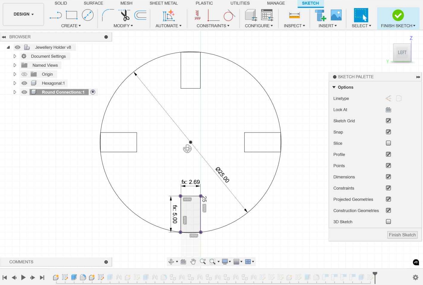
3- The next component was the rounded connection. I sketched it on the inner face of the tab. all the tabs width in all parts was= thickness-kerf as it's a X slot joint.
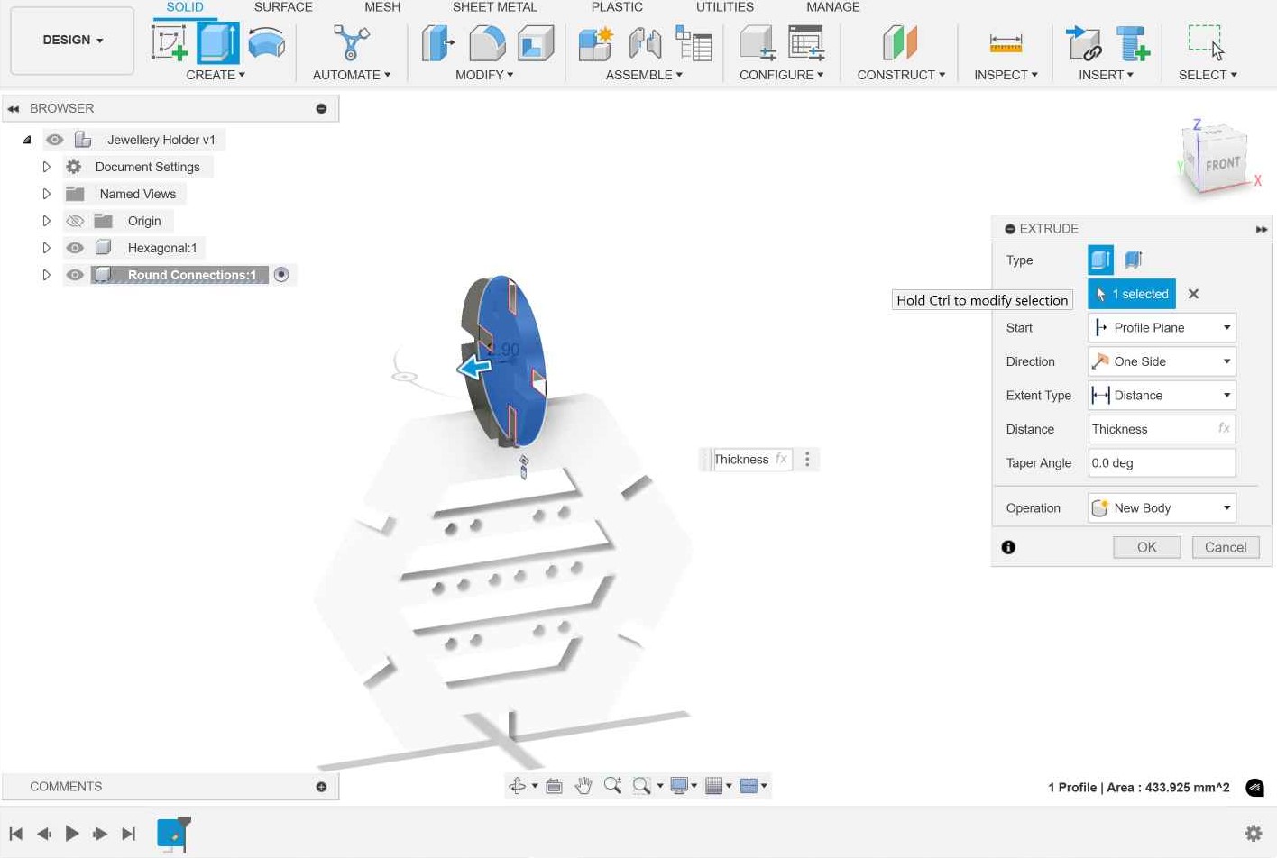
4- I extruded the sketch with the thickness parameter and made rigid joint between the two components.
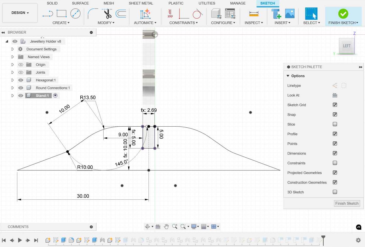
5- I then sketched the support part using lines then making fillets because spline was making it hard to fully define the sketch.
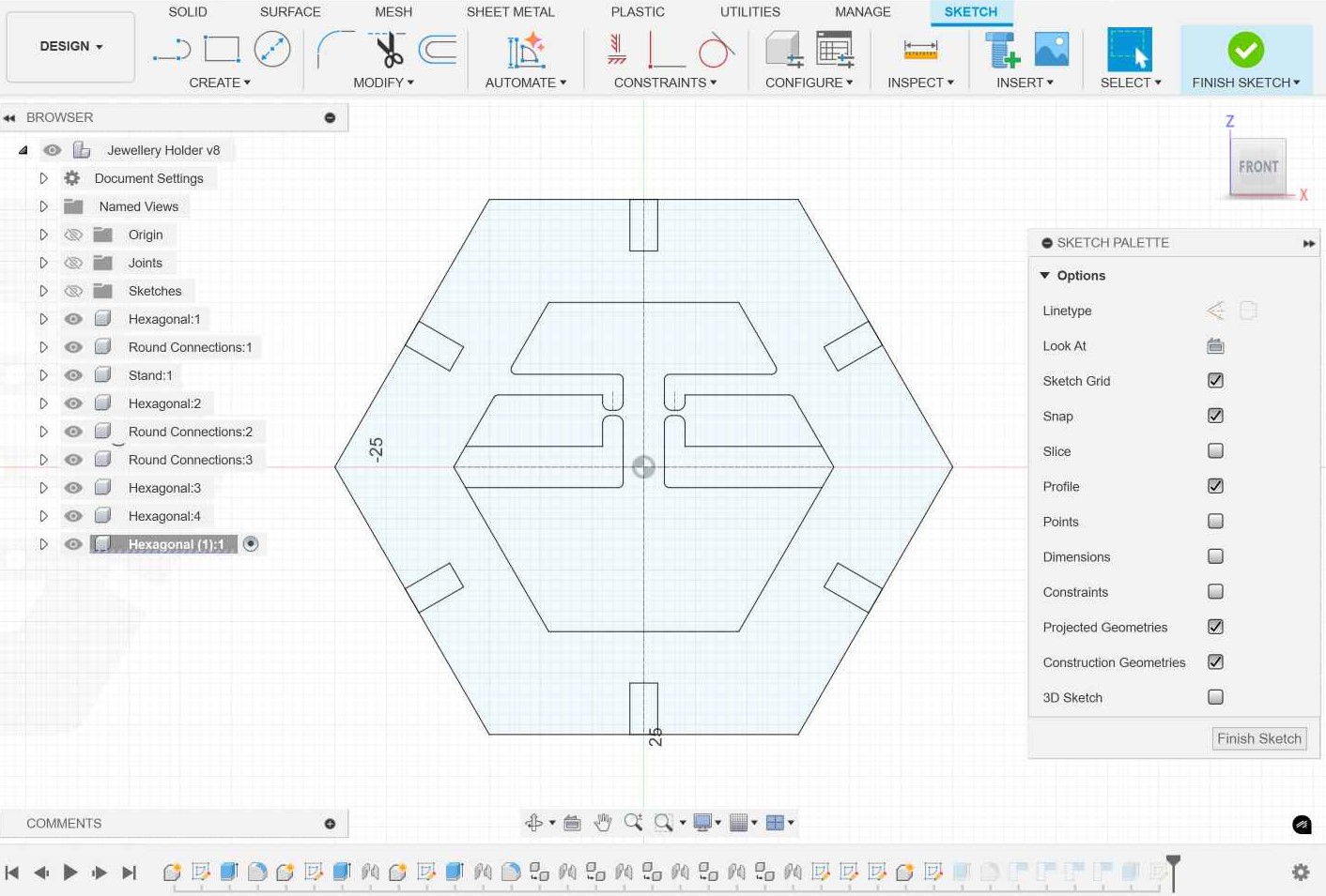
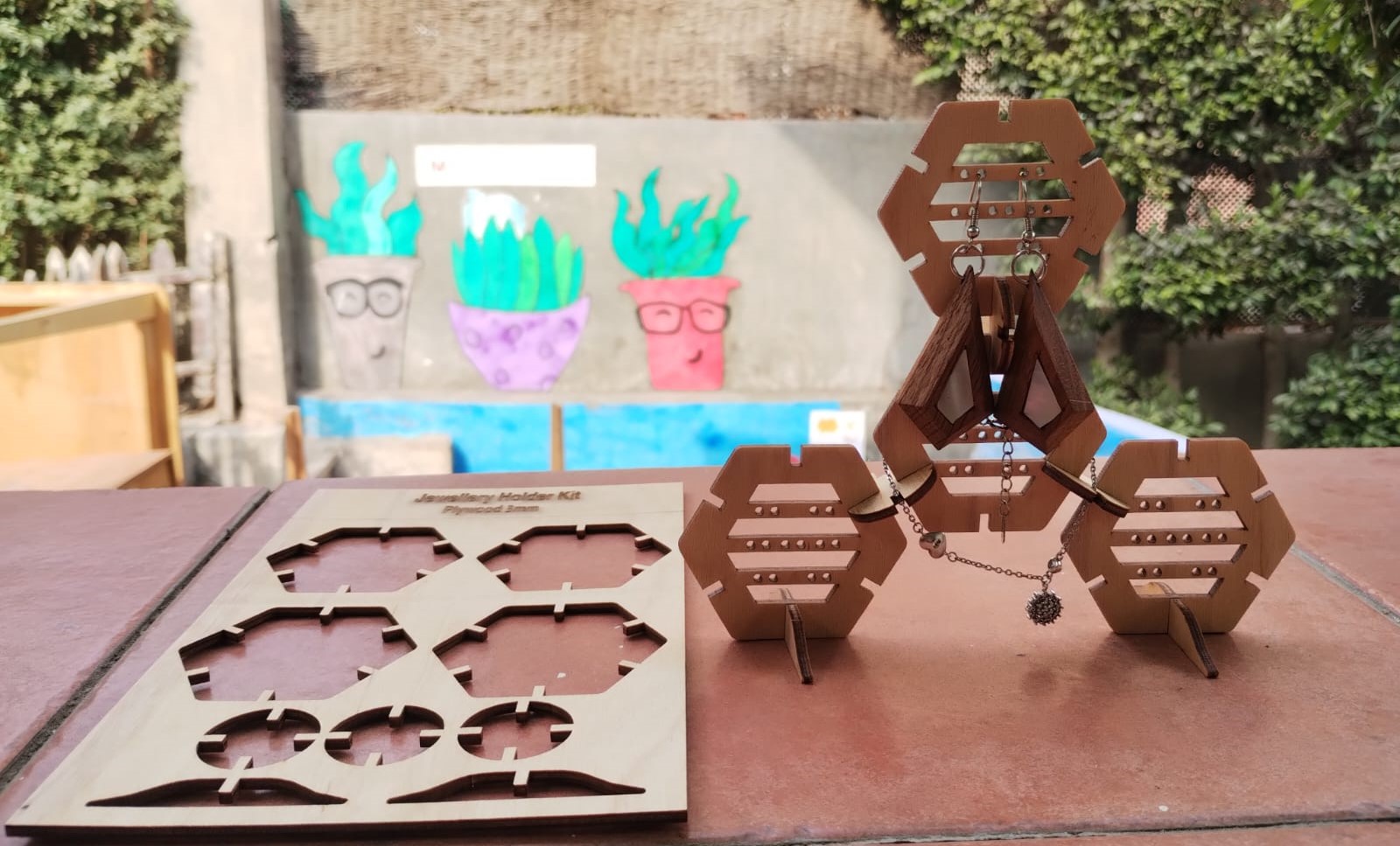
6- My instructor Noha suggested me to make another hexagon that would be suitable for holding rings. So I thought I would apply something inspired from the snap joint to holdd the rings in place without falling when moving the holder.
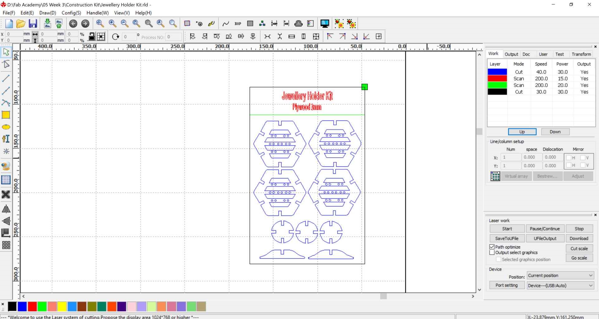
7- After exporting all the sketches as DXF, I imported them to RDWorks V8 and started nesting them. I decided to try making it as a kit card so I set the cutting speed of the parts to 40 instead of 30 to try if it would hold the parts in place without them falling from the card.
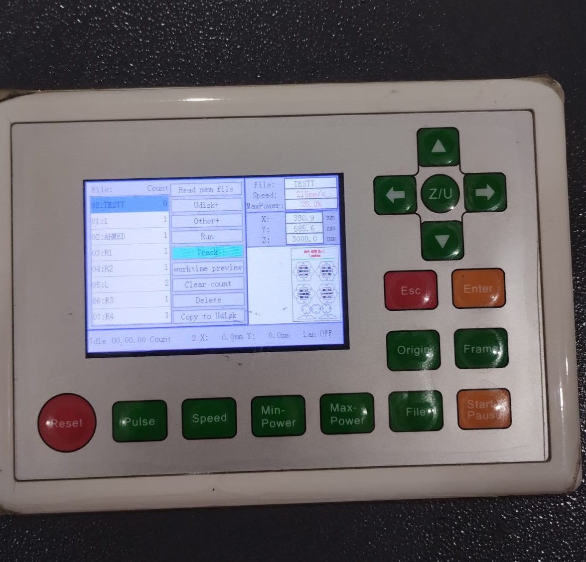
8- I connected my laptop to elmalky through USB. Put 3mm plywood sheet in the workarea. Set the origin and tracked the area of working then choose Run after turning on the laser cutter fume hood.
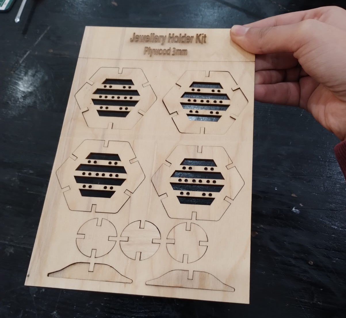
9- Luckily the speed change worked fine and I removed the parts then replaced them again and they didn't fall.
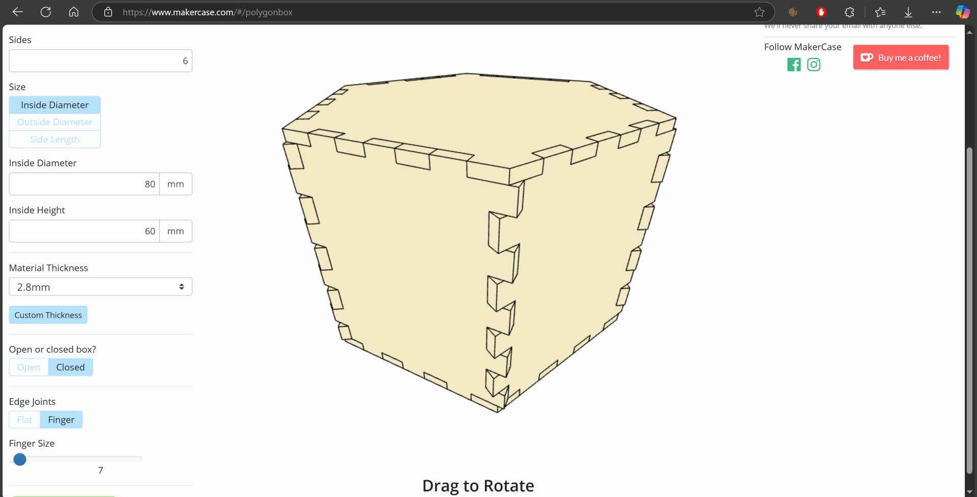
10- I wanted to go bigger and my instructor Noha was viewing a site called MakerCase with us, so I decided to give it a try to make a box for my constrution kit. I chose polygon box and filled the needed info.
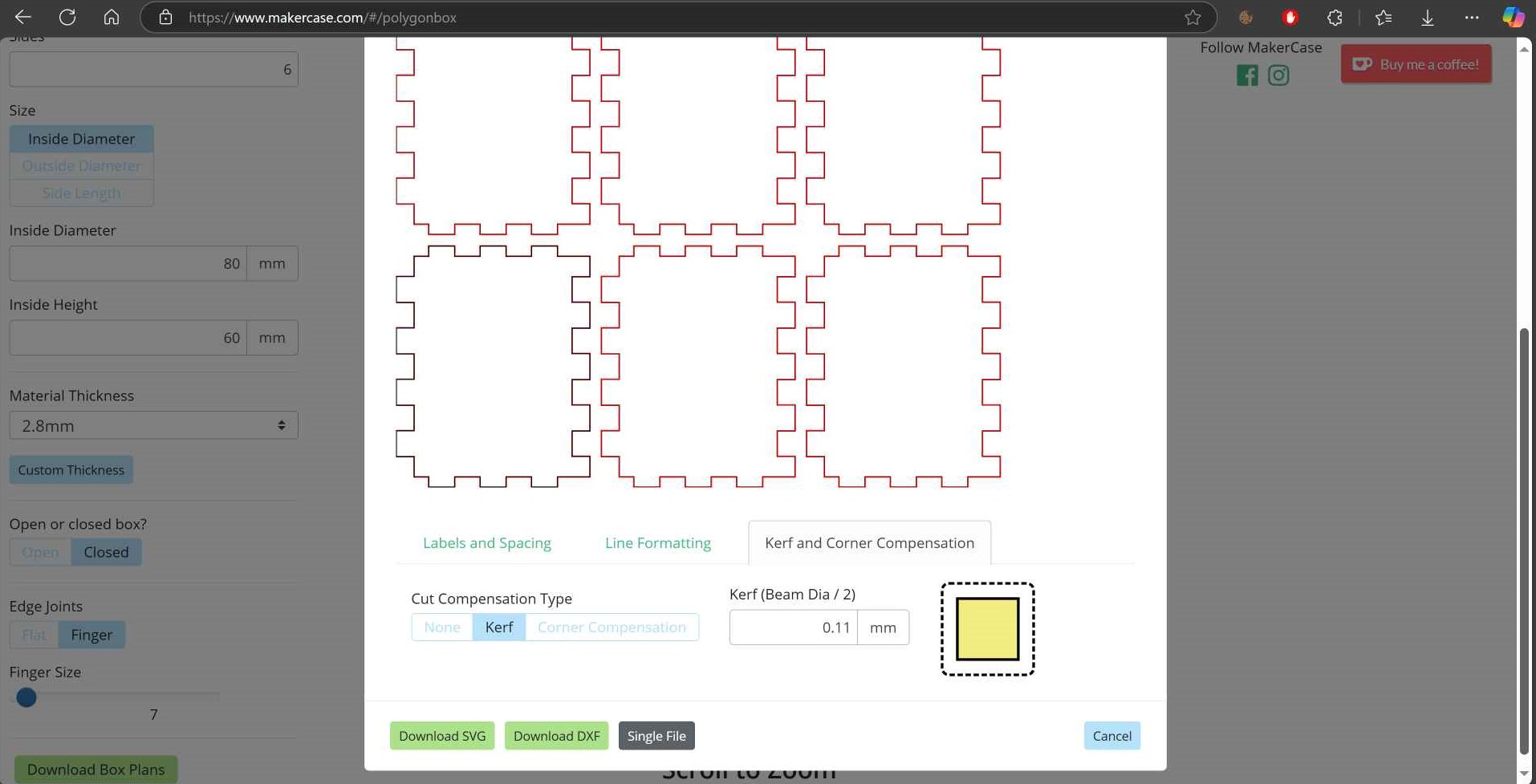
11- I clicked download box plans then set the kerf and downloaded them as DXF. I repeated the same previous steps to cut them on the laser cutter. The box was hammer fit actually and was tricky to assemble it.
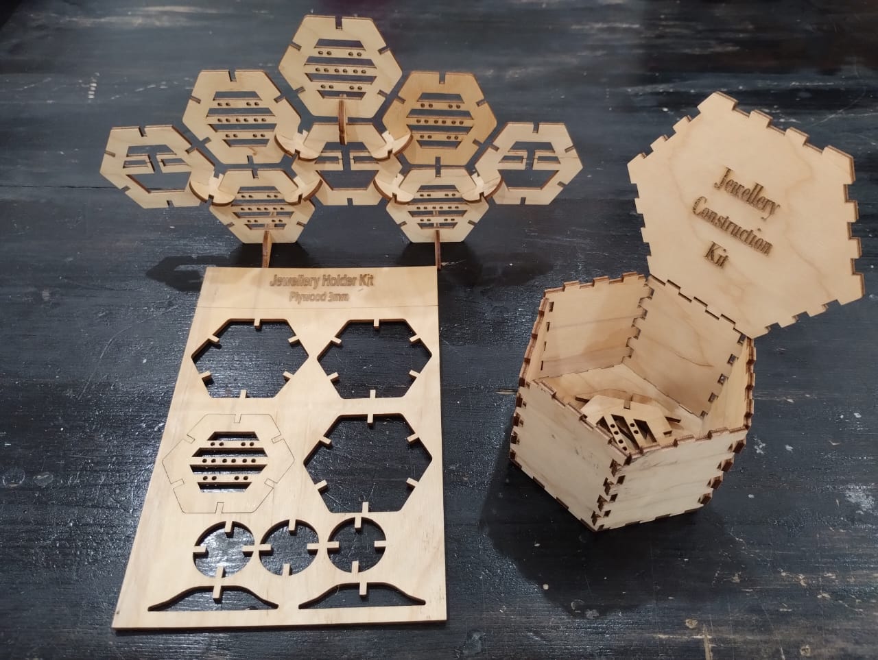
12- But the final output of the whole process was worth it. ^_^