
Electronics Production
Here's a summary about what you'll see next:
- 1) Group Assignment
-
- China Machine and tools
- Traces Test
- 2) Individual Assignment:
-
- Preparing PCB for Fabrication
- Fabricating PCB
- Stuffing and Soldering
- Obstacles along the way and NOT TO DO things
- Planty PCB Upgrade
- 3) Original Files
1) Group Assignment
In this week we should Characterize the design rules for our PCB production process, and get to know how to send a PCB to a boardhouse.
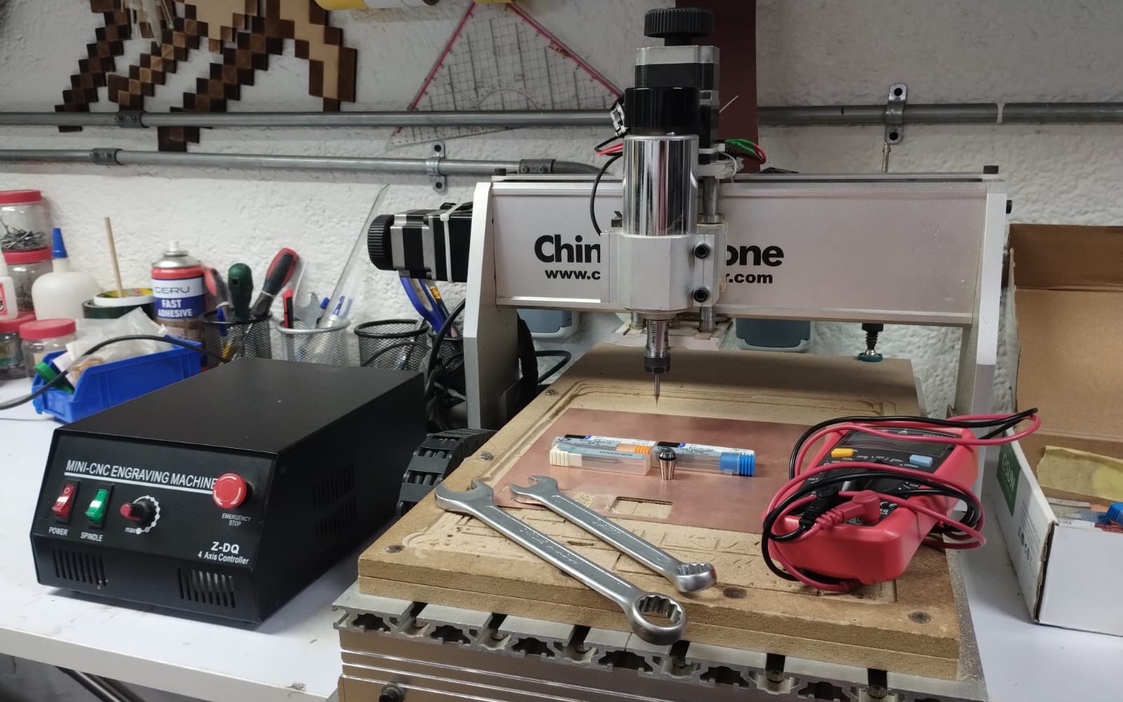
First of all let's get to know our China CNC Router and how to use it. First we power it up from the red switch on the left. We need 15 and 17 wrenches to change collets and tools, our hands get away from each other when we want to loosen the tool, and we bring them closer when we want to thighten the tool and hold it well.
When we start operating the machine we open the green switch to turn on the spindle and we control its speed from the potentiometer next to it. Your saviour and best friend in this machine is the Emergency Stop Button, when you here any weird noise or anything goes wrong, just hit it quickly.. Trust me you'll need it and you should never leave the machine unattended.
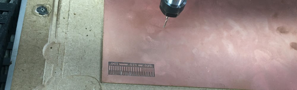
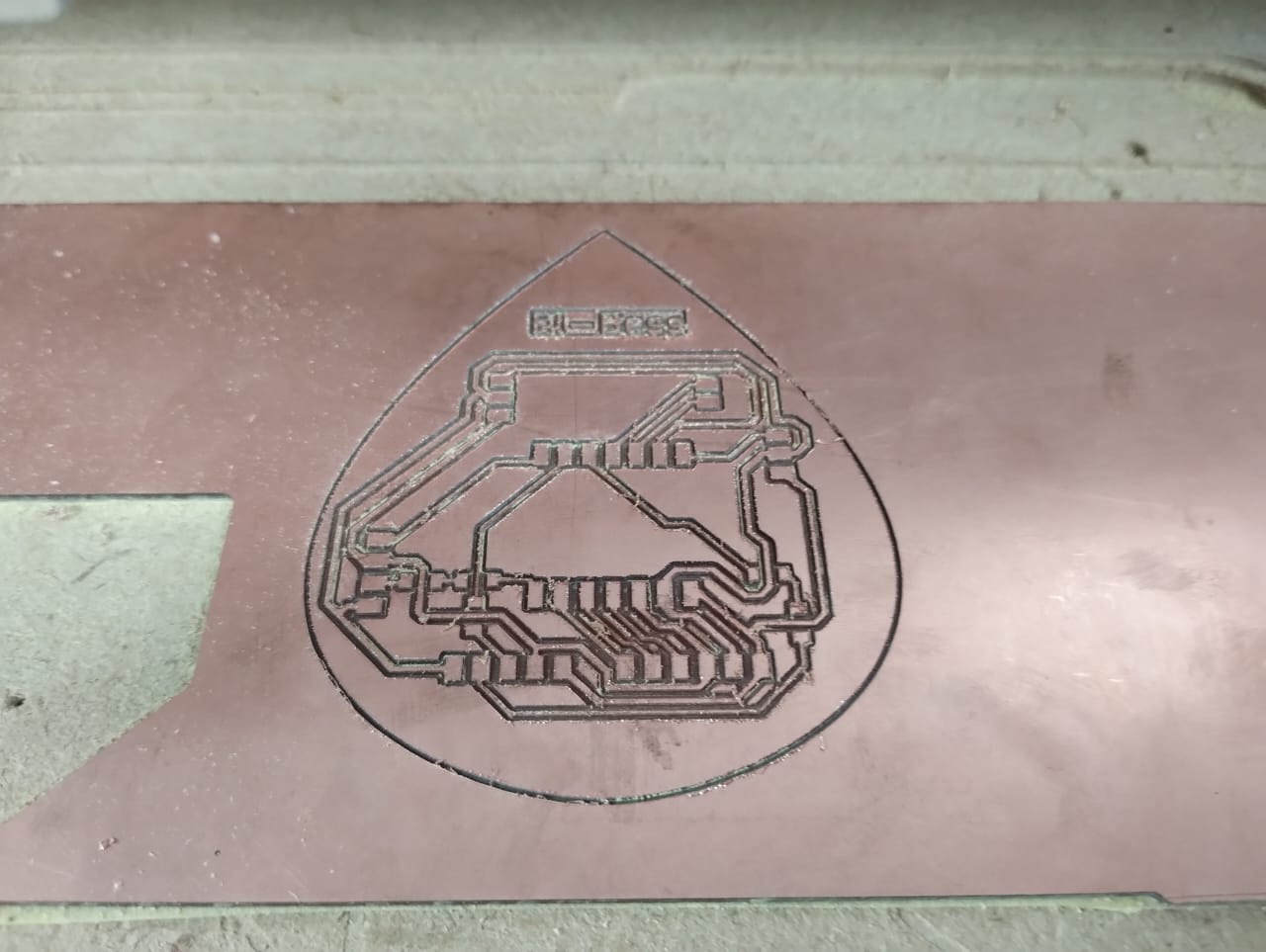
So now for the design rules we used mods to test the traces as Eman prepared the traces file for fabrication. I prepared the fr1 PCB to be mounted on the machine and added the endmill to the machine. We used a 0.4mm endmill and here are the results.
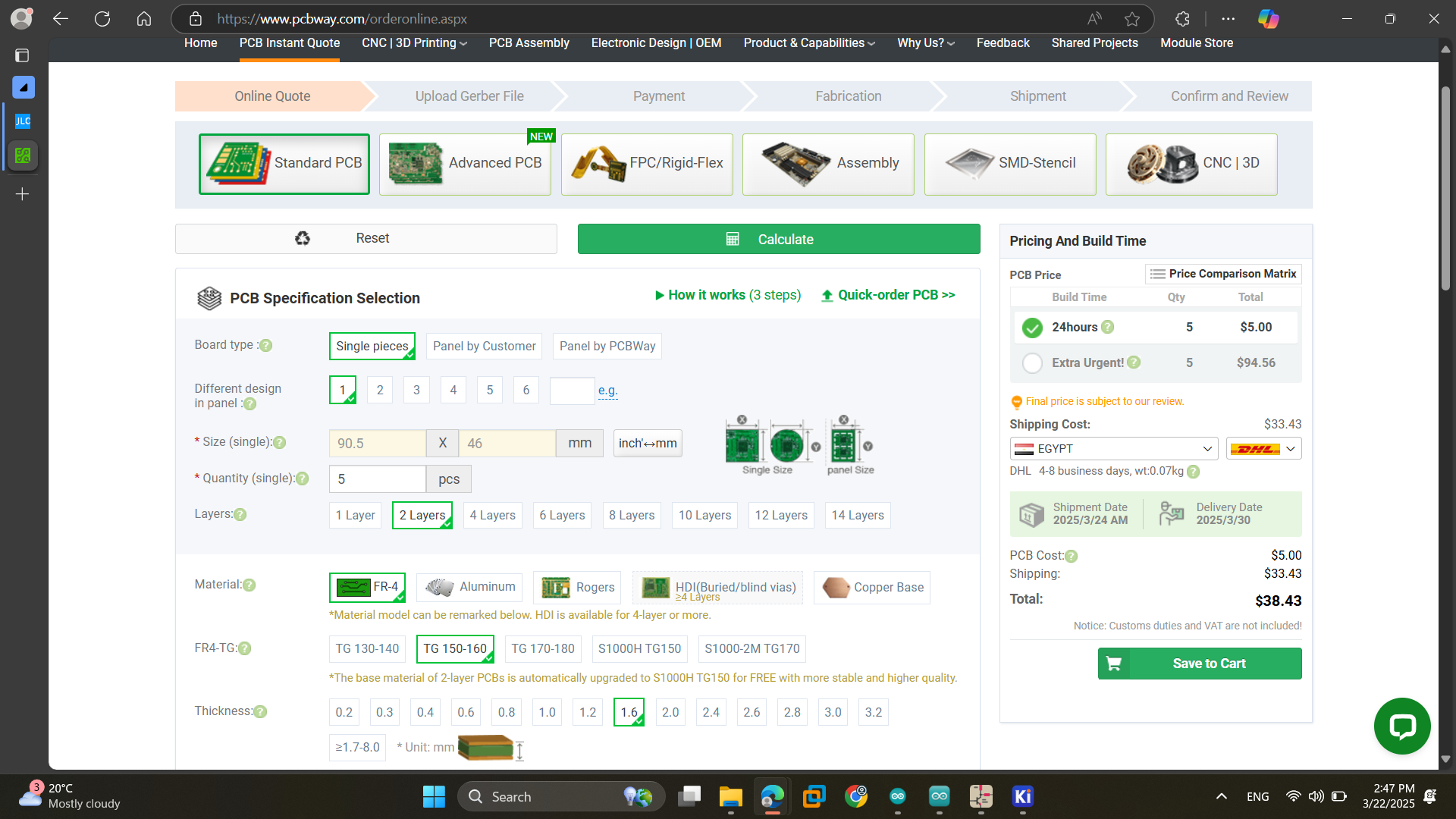
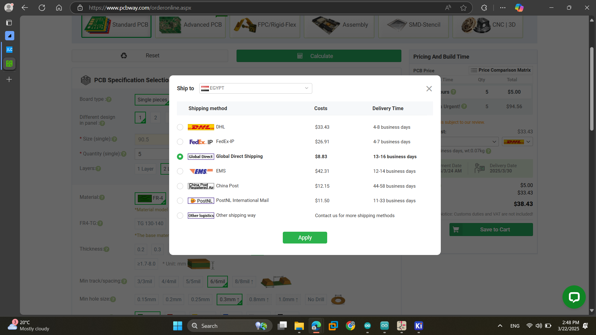
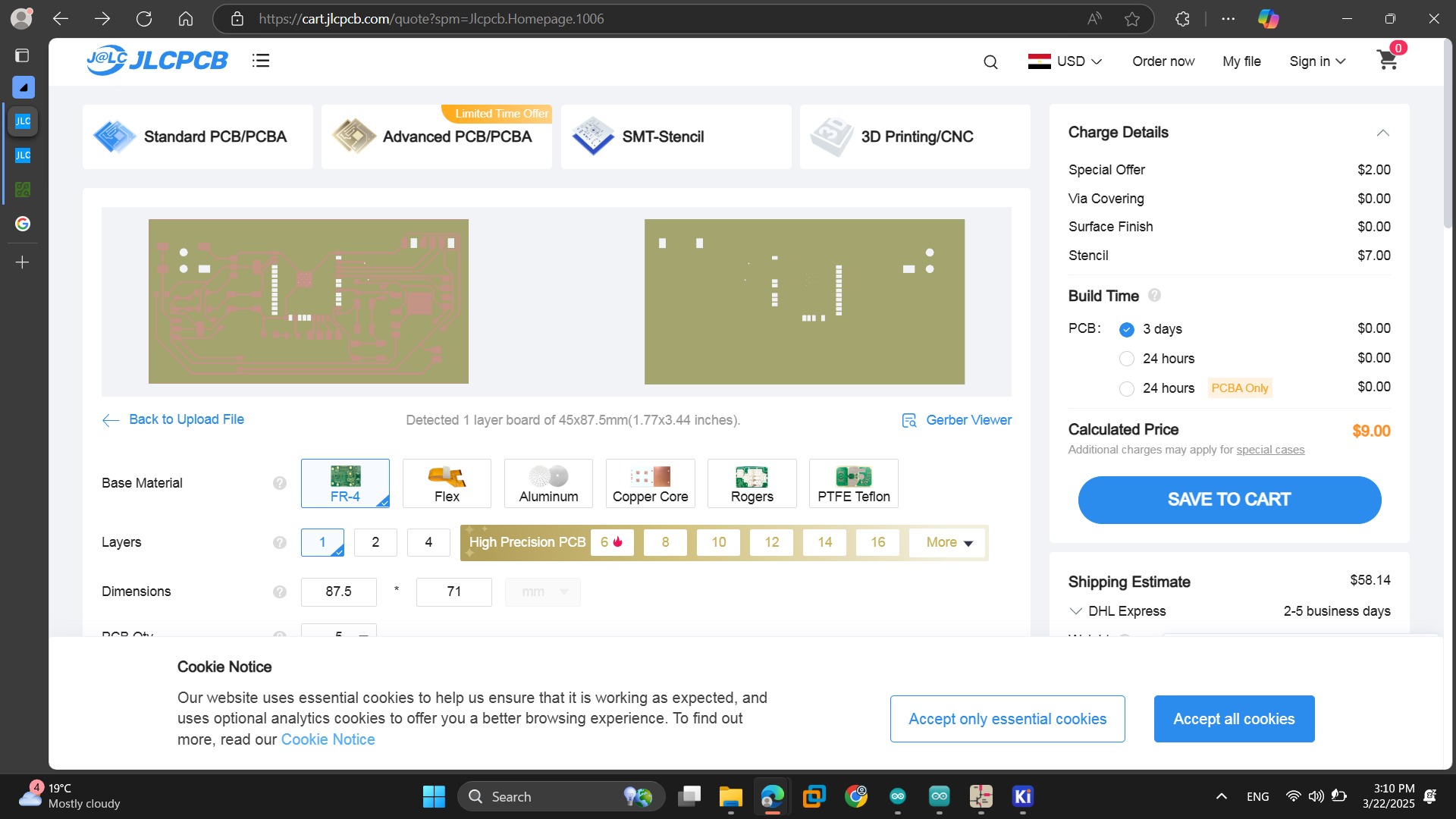
As for submitting the PCB we tried PCBway and JLCPCB. We uploaded the files and set the PCB specifications. We tried different settings and saw different shipping methods to define the best suitable options with best prices and less delivery time.
2) Individual Assignment
This week was exciting and totally new to me as we are working on electronics production and bringing a PCB to life. I produced 2 PCBs one for my final project and the other preparing for the output devices week.
1. Preparing PCB for Fabrication
First of all we have to prepare the PCB to be fabrication.
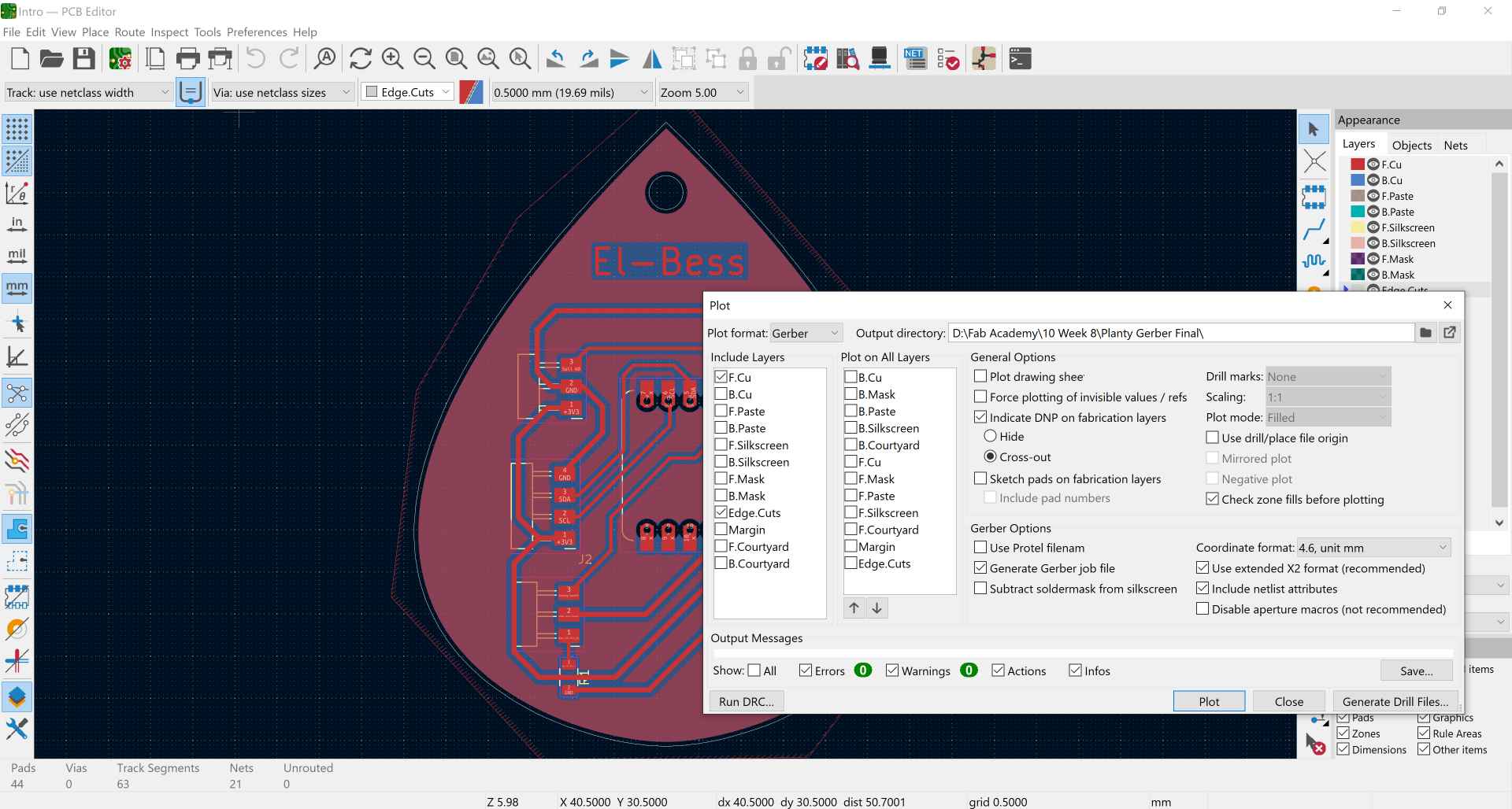
1- In the electronics design week we ended up making the PCB design on KiCAD. Now, we choose plot and select the layers we need which are the traces in F.Cu and outline in Edge Cuts.
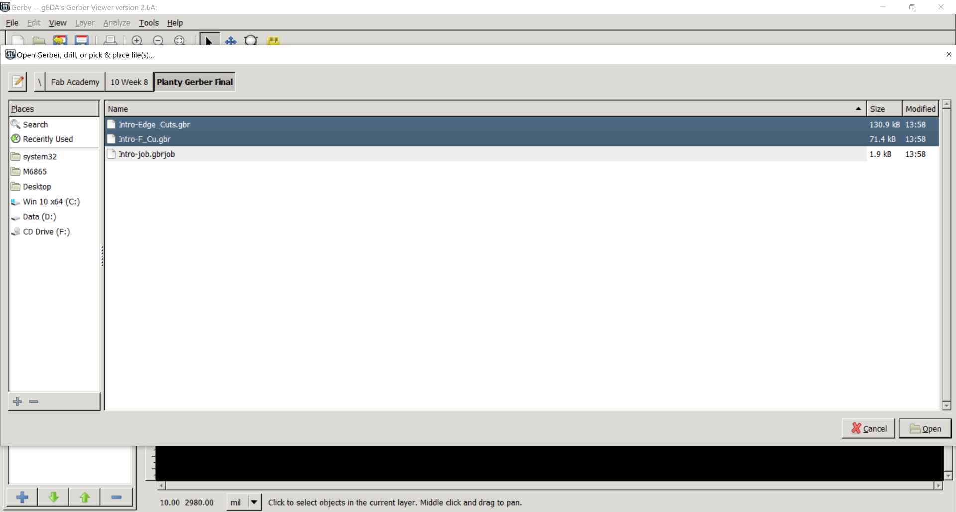
2- After exporting them from KiCAD we import them to Gerbv which is a software like kicad gerber viewer.
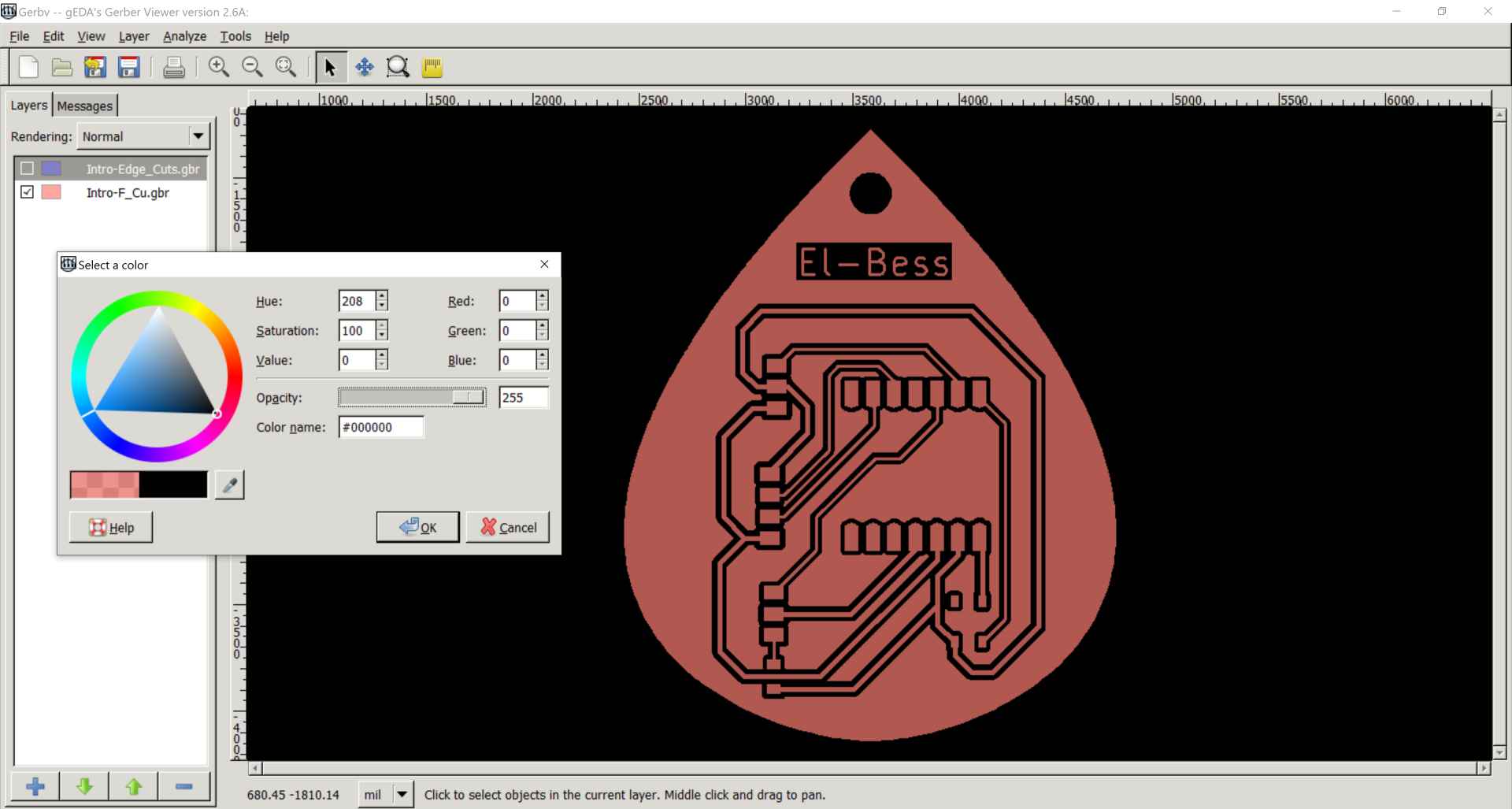
3- By clicking on the colors next to the layers we change the color to black and increase the opacity to 255 then save the 2 layers together as pdf and the outline alone as another pdf and make sure you write .pdf when naming the file.
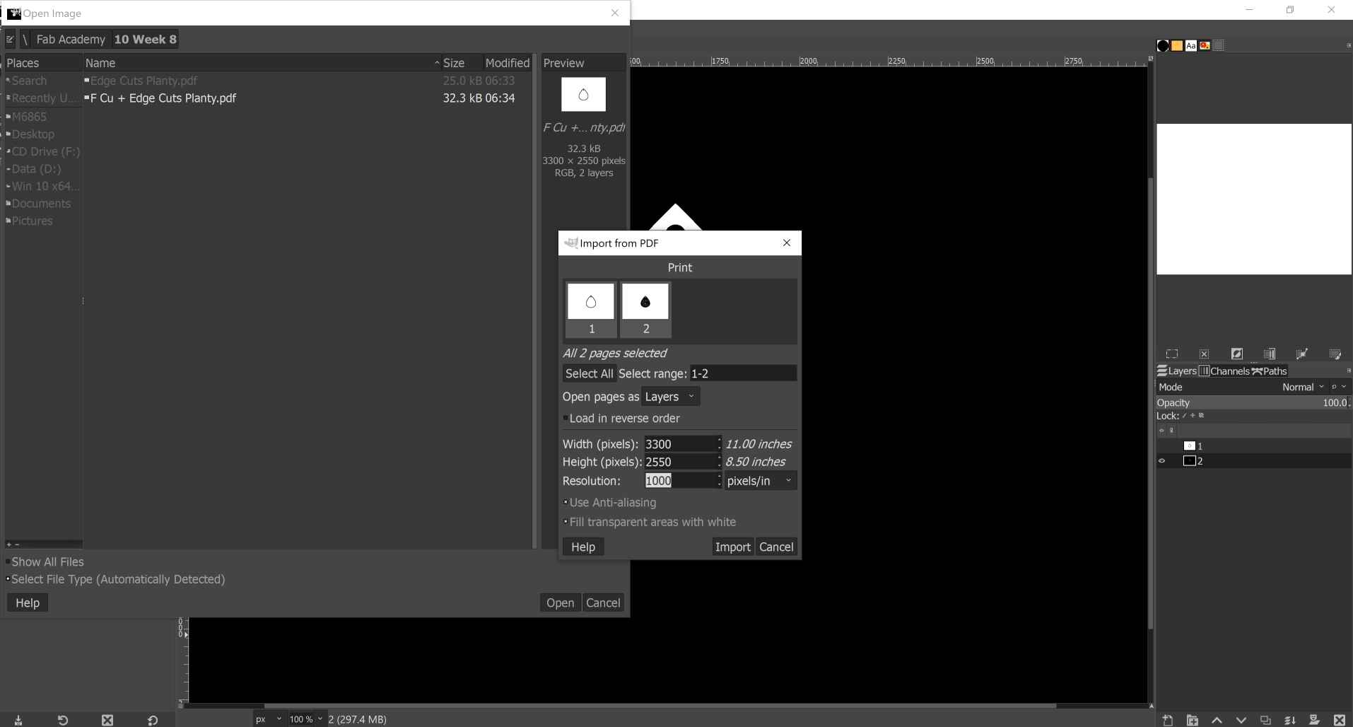
4- Next, we move to Gimp software and import our pdfs and change the resolution to 1000 pixels/in.
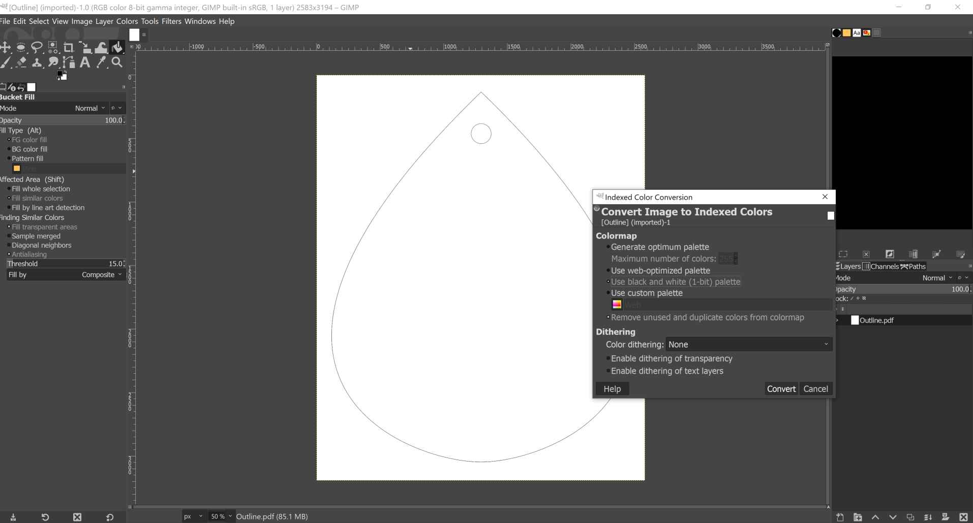
5- By going to image menu then Mode and choose Indexed we make it black and white.
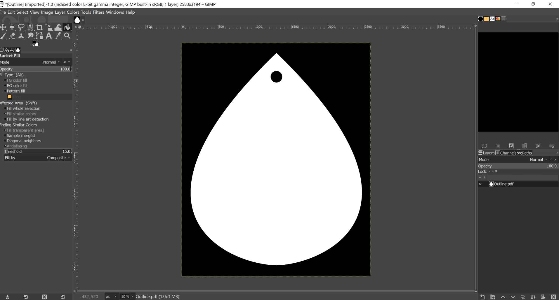
6- After that we use the paint bucket to fill the areas we want to cut with black color.
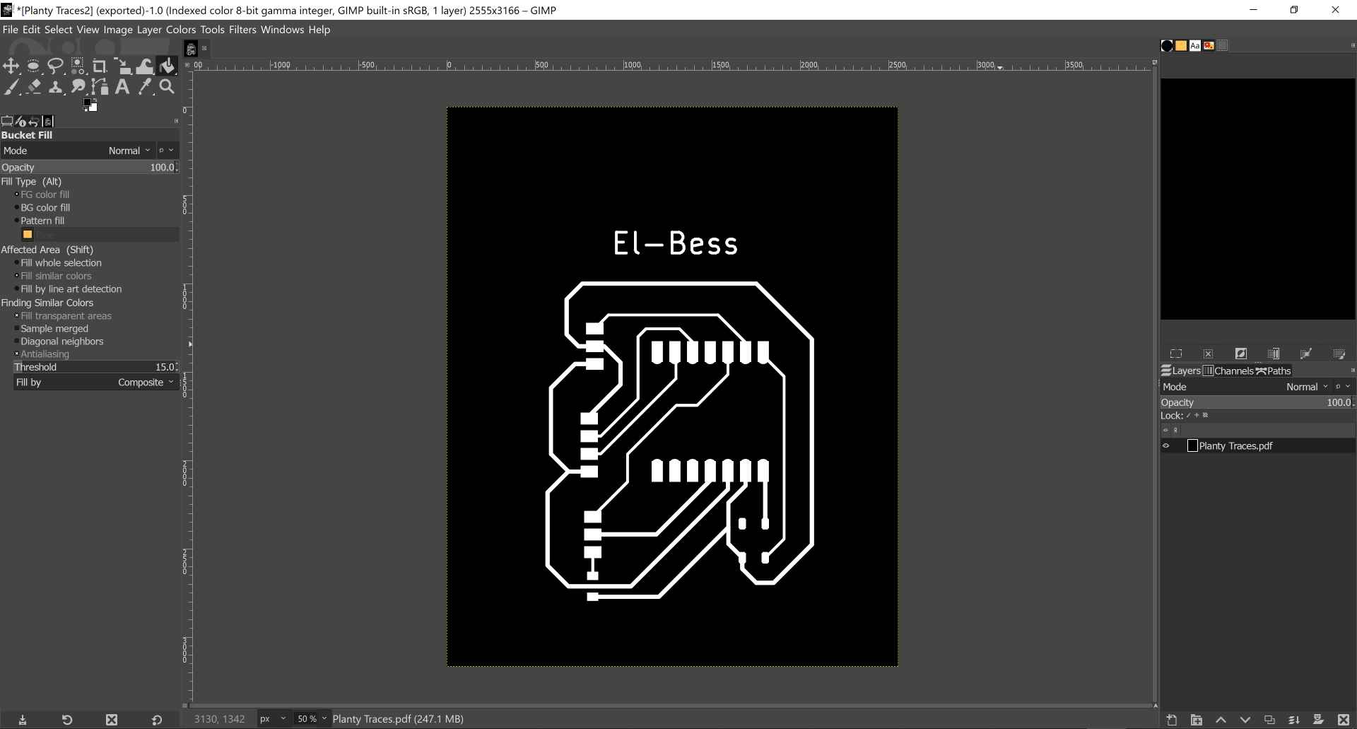
7- In the traces layer we go to colors menu and choose value invert and leave only the traces with white color and remove any other white area by replacing it with black. Then we export them as png. "There's a mistake here will be explained in the obstacles section, could you guess what it is?".
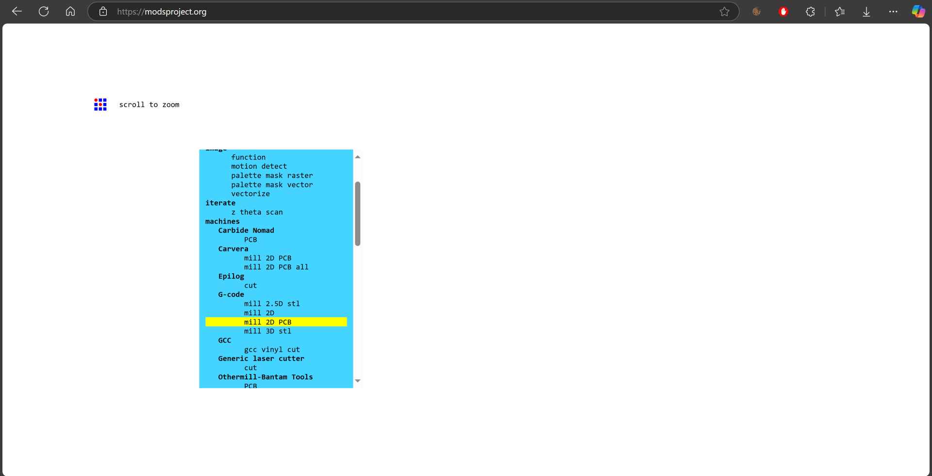
8- Now it's time for final steps to make g-code for the machine. By going to mods you right click any where --> programs --> open program --> machines - G-code - mill 2D PCB.
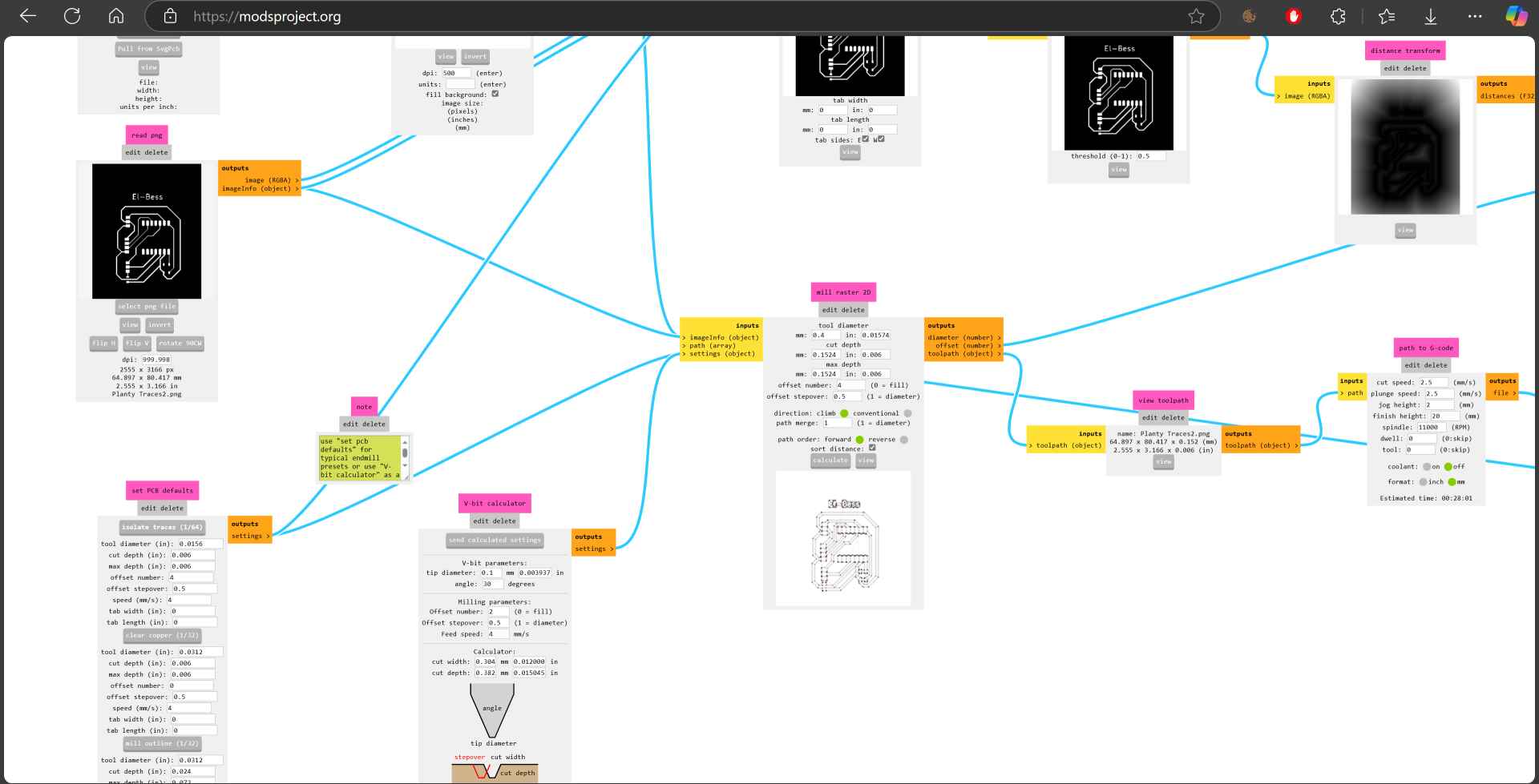
9- First we select the traces png file and in set PCB defaults we choose isolate traces 1/64. Then in mill raster 2D we define the tool diameter which is in our case 0.4mm then calculate and the nc file will be downloaded automatically.
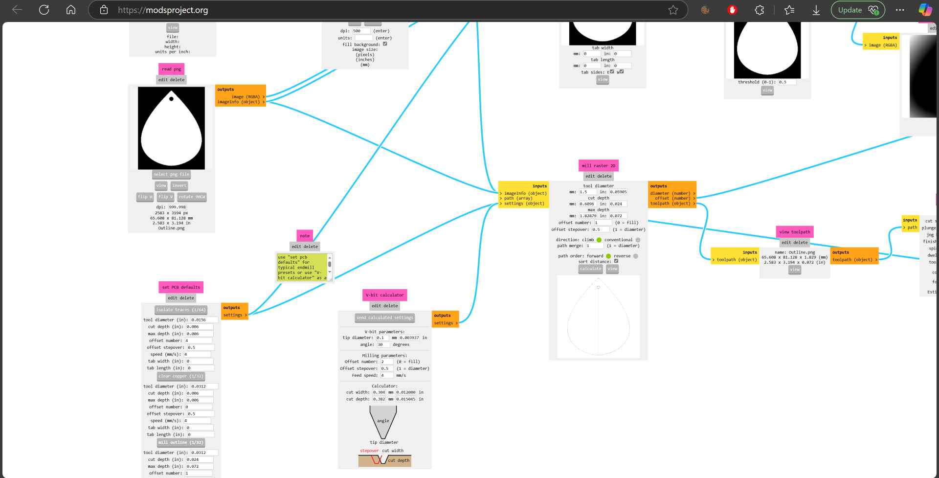
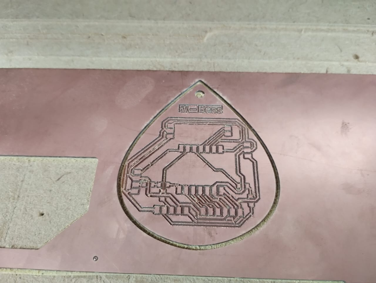
10- Then we import the outline png and choose mill outline 1/32 and in the mill raster 2D I made the tool diameter 1.5mm then clicked calculate. Now we are ready to jump to the next stage to fabricate the PCB.
2. Fabricating PCB
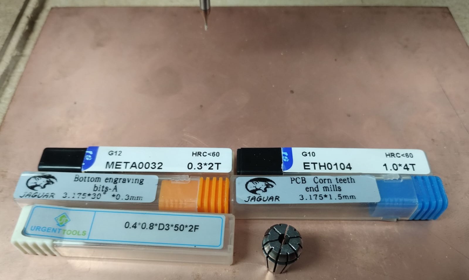
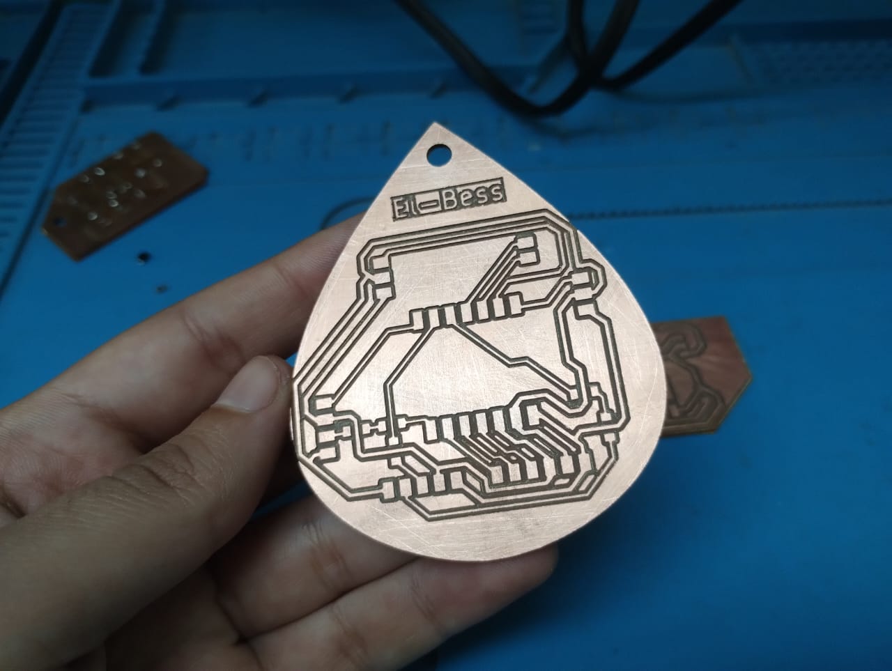
To start fabricating let's get to know more about the tools that we use in this machine. We have endmills and V-Bits. For milling the outline we can use the 1.0mm or 1.5mm but I used the 1.5 here. And for isolating the traces we could use v bits but it needs caution in the z position as it should barely touch the PCB to isolate good traces and not too much, so I used the 0.4mm endmill which was better but could break easily.
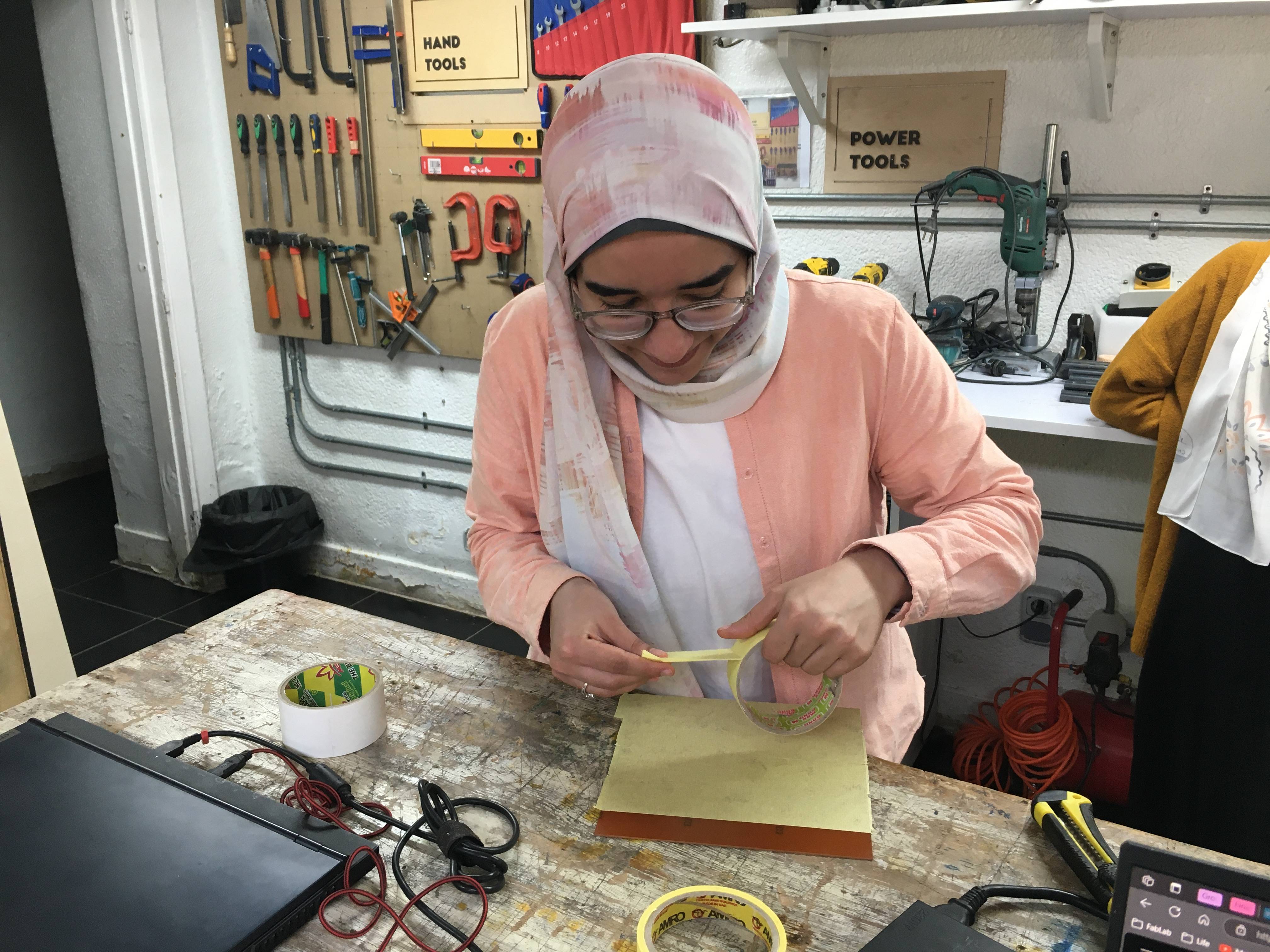
To secure the workpiece on the wasteboard on the machine, I first put yellow tape next to each other on the back of the workpiece, don't overlap the tapes and don't leave any gaps, you want a smooth surface. After we finish the scotch or the yellow tape we put double face on it the same way and press on the workpiece well to the table to hold everything together. Last but not least we remove the other side of double face and secure the workpiece on the waste board.
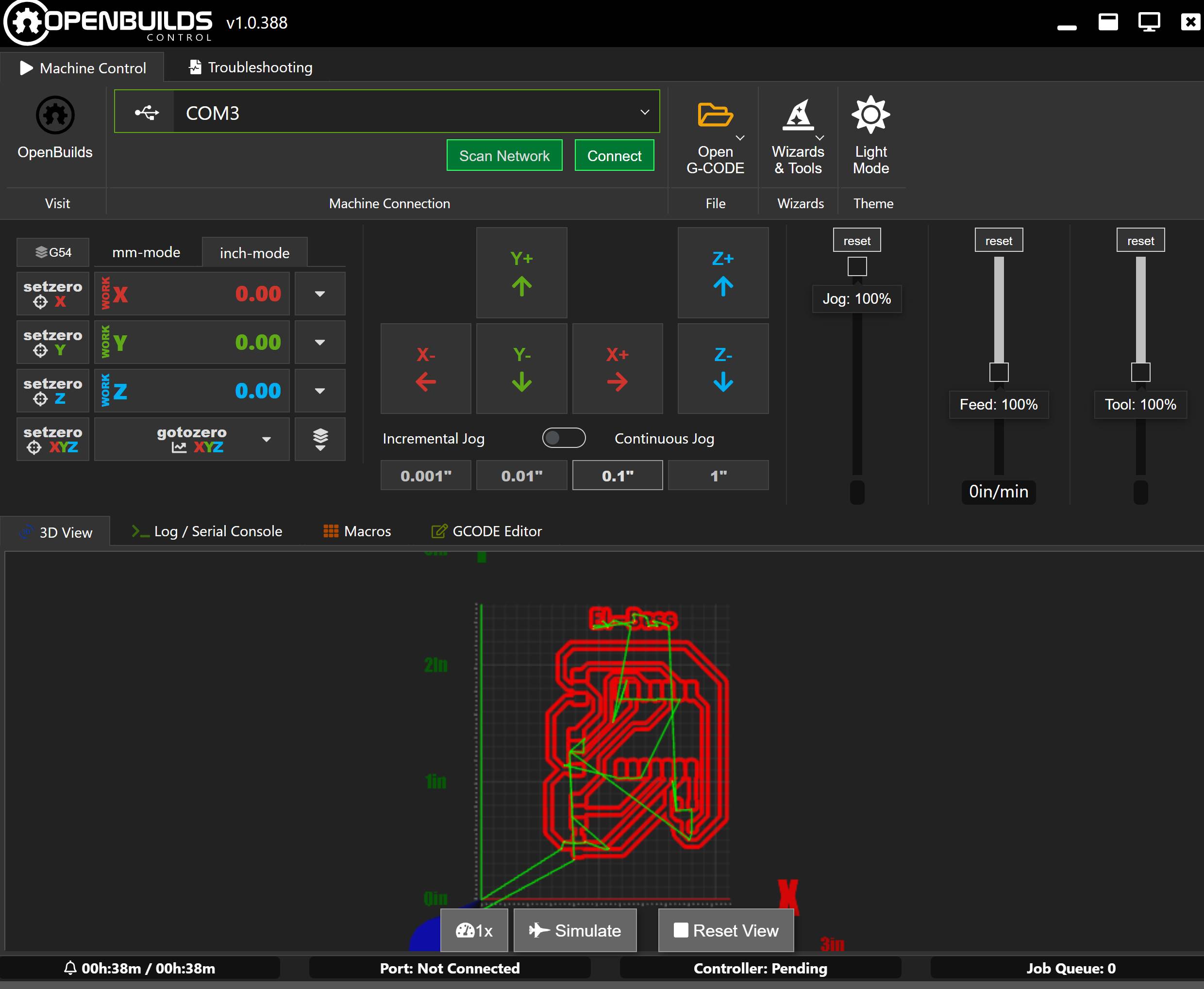
We control the machine using Openbuilds Software. This is the interface of the program, after we connect the laptop to the machine via USB we click on connect. I open the G-Code I need which is first the traces. I switch to mm-mode, then I start moving the spindle around using the mid section and control how far I want the axis to go from the 4 buttons under it. When I'm satisfied with the tool position I set zero x and set zero y then turn on the spindle and start going down in the z little by little till it barely touches the workpiece and now I set zero z and I'm ready to go.
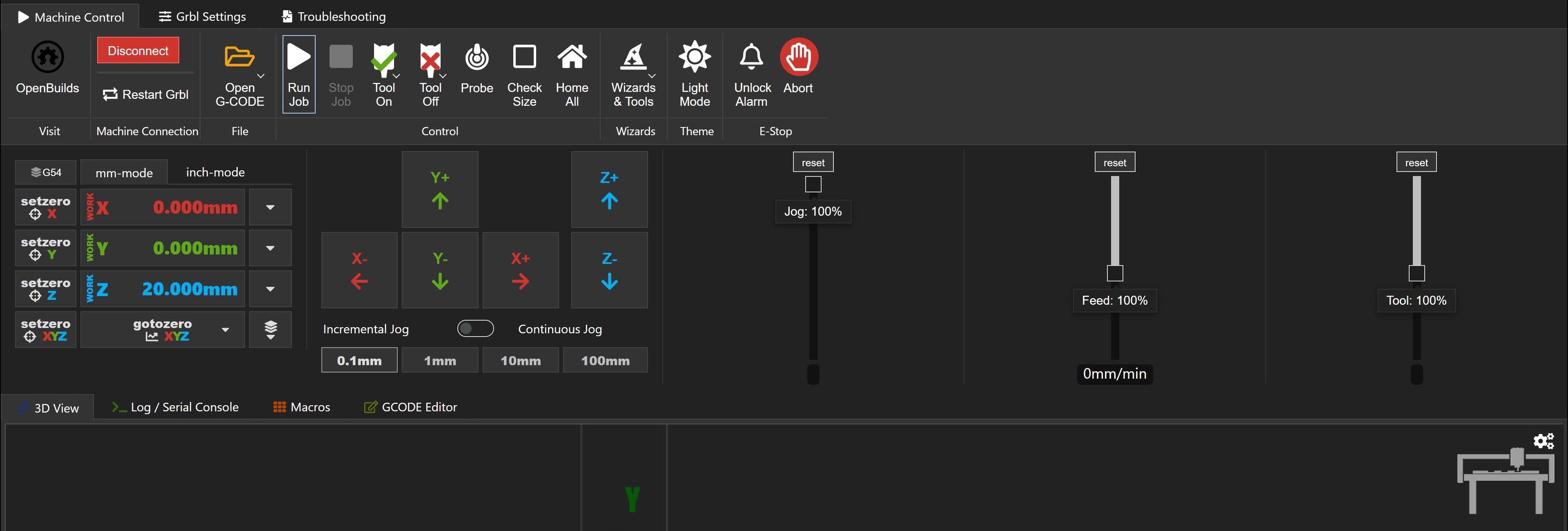
When you connect to the machine there are more options that appear. If you try to move the axis and they don't move check the unlock alarm button. If you want to check the size of your workarea you can lift the tool up in the z axis and click check size. When all set just click run job and keep your eye on the machine while working, sure thing while wearing safety goggles.
When the traces are done we clean up the workpiece and then change the tool to 1.5mm endmill to start making the outline or drill first if there's any.
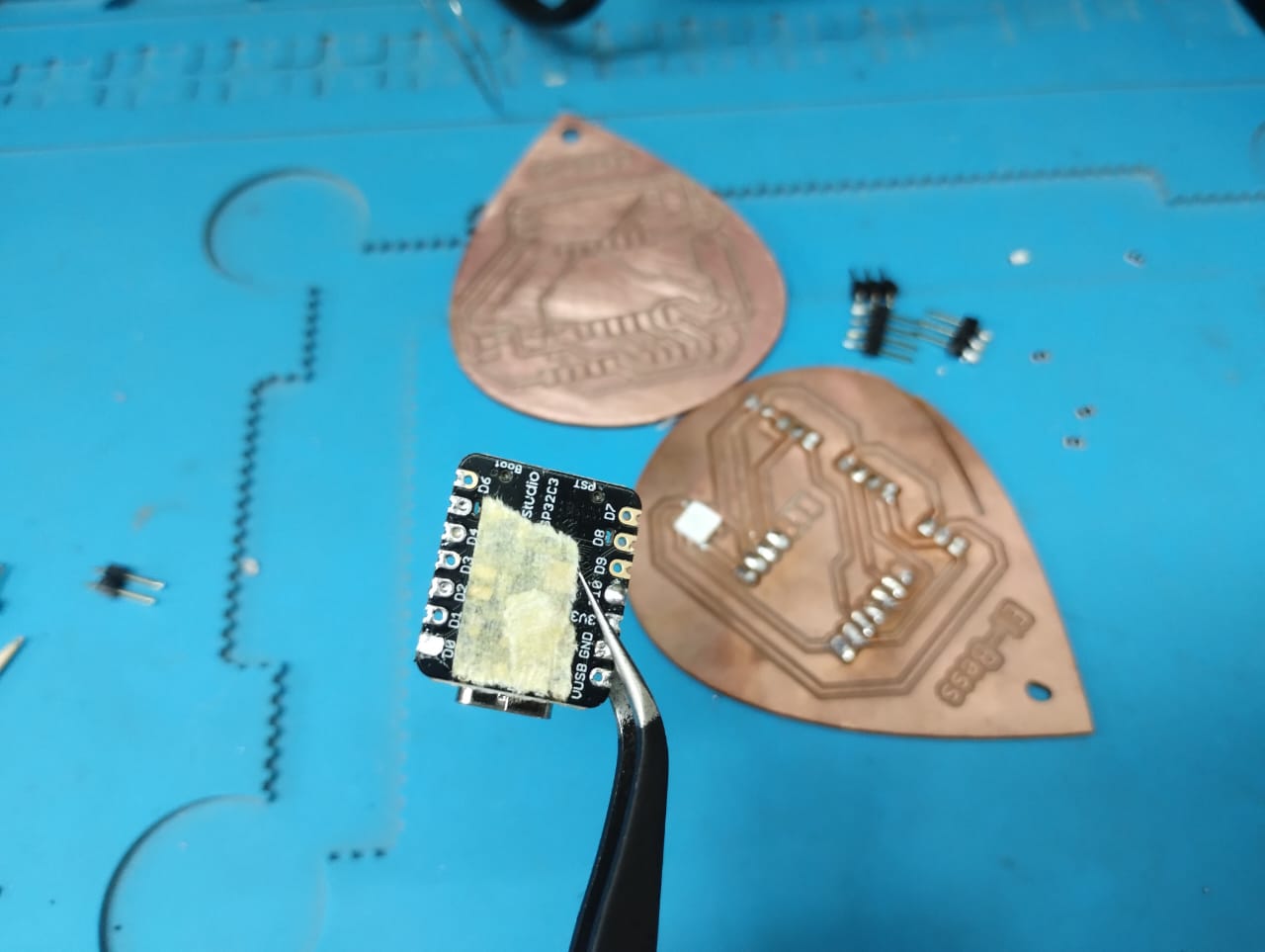
3. Stuffing and Soldering
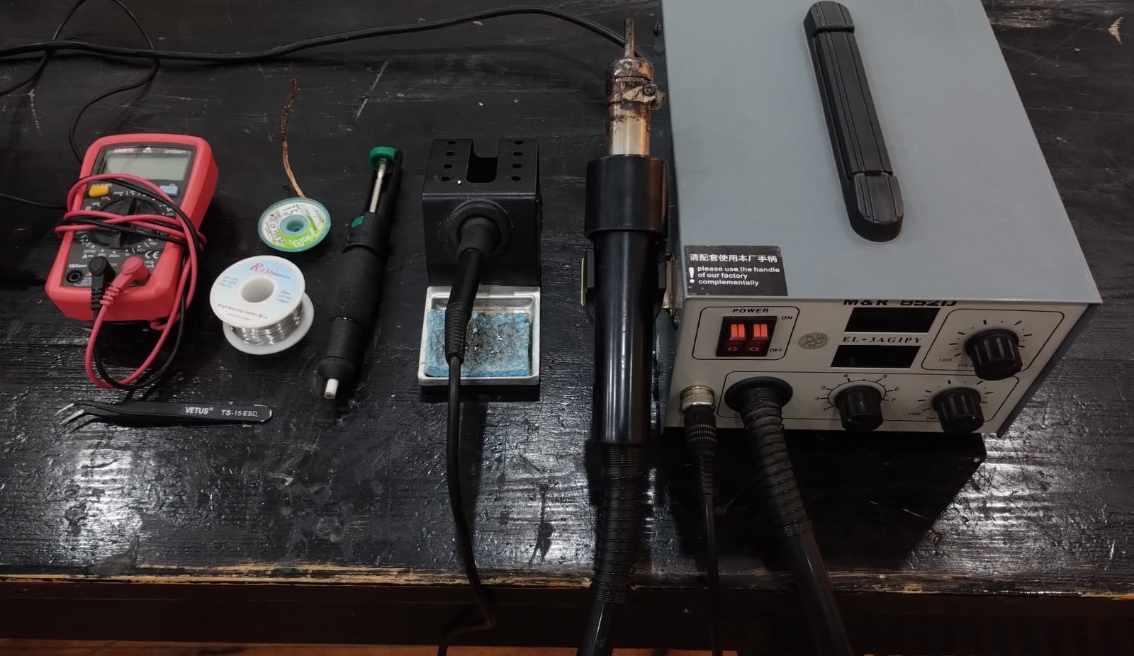
Now another fun part comes which is soldering. We need soldering station that has soldering iron and a heat gun, cleaning sponge, solder wire, insulated tweezers, solder wick, desoldering pump,solder paste, toothpick, and multimeter.
We start by doing a Continuity check using the multimeter to make sure all traces are good.
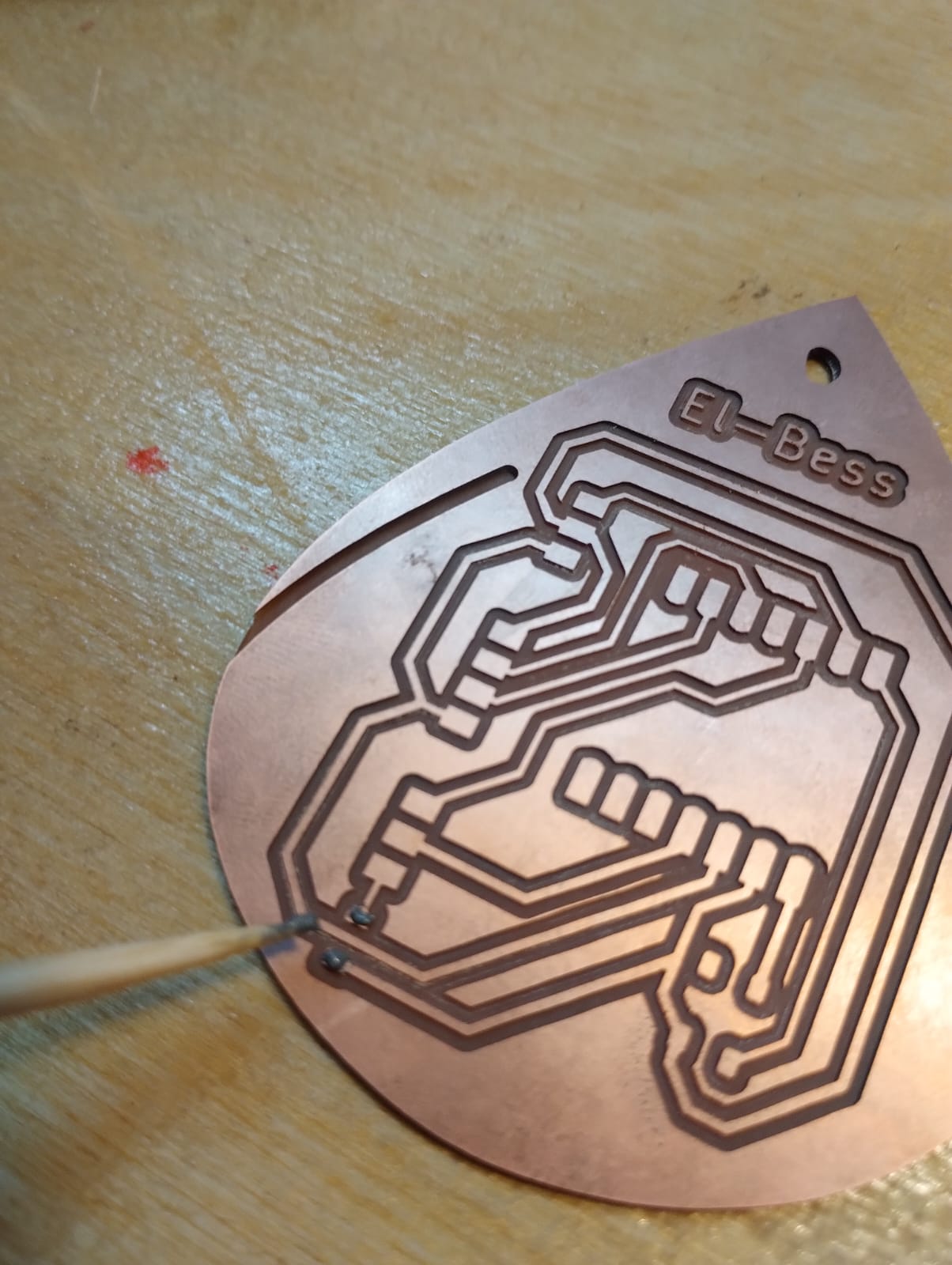
1- For small pads I used a toothpick and soldering paste to put it on the pads then hold the small component on it using tweezers then heat it up with the heatgun.
2- This was my first 0 ohm resistor to solder and my first time using soldering paste. ^_^
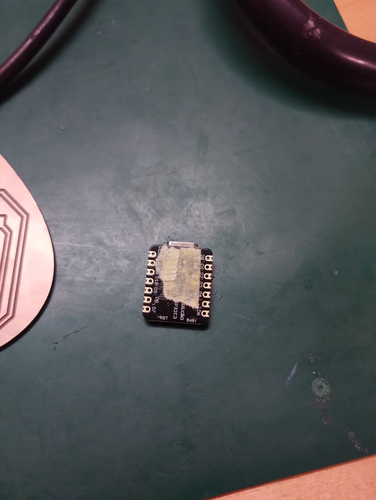
3- I was worried when I solder the xiao that the pads on the back of it will be connected together so Amr suggested I put a yellow tape on them to isolate them.
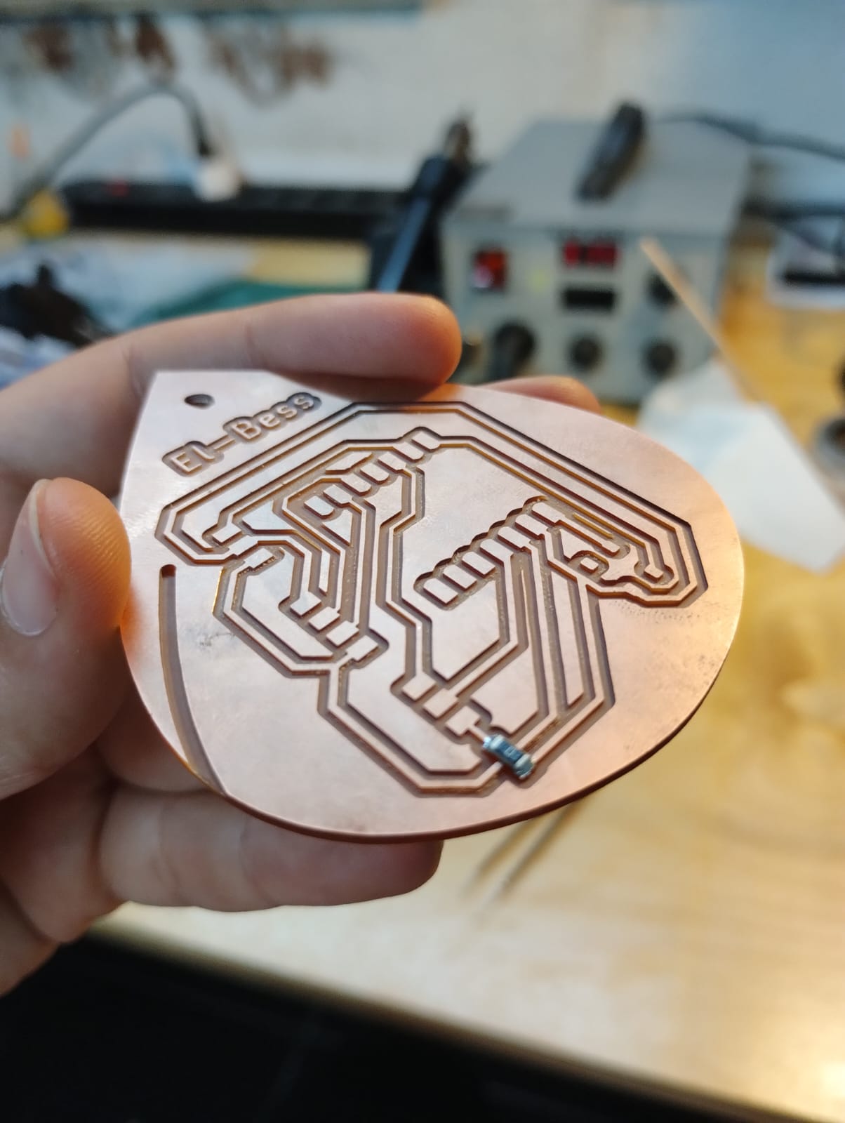
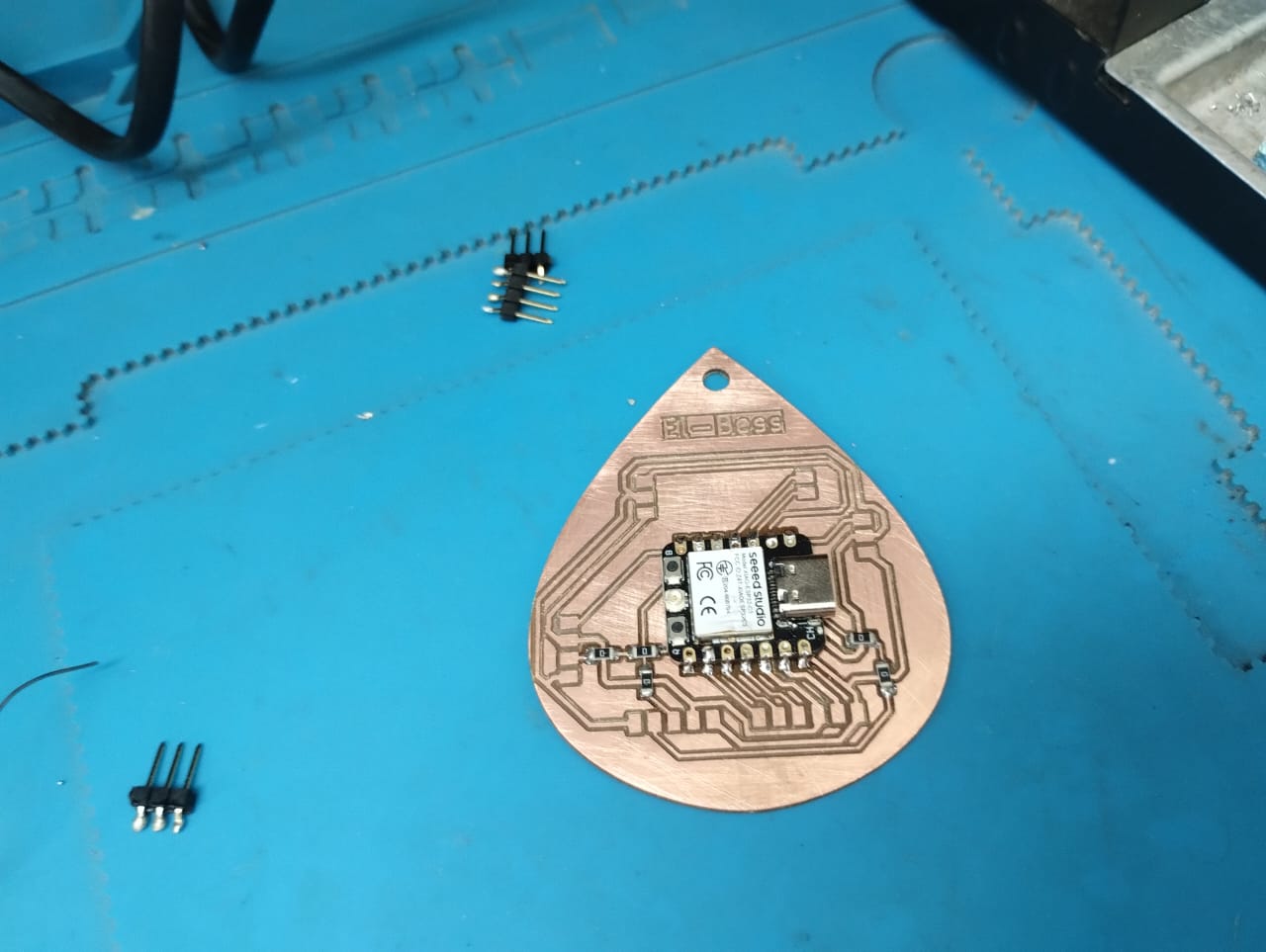
Here you can see the PCB soldered successfully. Some tips and tricks of how to solder:
- Heat up the pad first for about 2 secs and add some solder on it. Add the component by holding it with tweezers and heat the solder you added. Now you can add solder to the other pins after having the component in place.
- If you have a lot of solder added you can use the solder wick to absorb it or use the desoldering pump to suck it up.
- Start from inside to outside. Meaning, solder components in the middle first then go wider to help you solder easier.
- Use soldering paste and a toothpick for small pads.
Now we can see that my PCB is working well. ^_^
The other PCB will be documented in the output devices week.
4. Obstacles along the way and NOT TO DO things
1- Here was my first problem dealing with the machine as I heard unfamiliar sound while the machine was working and when I looked I saw the workpiece moving and not well secured to the waste board so I ran to the emergency button. This made me make sure I clean the waste board very well and press with force on the workpiece to make sure the double face holds it in place.
2- My second and third problems are shown here in this video. Frist one of them that you notice there were a track started and didn't finish. This is where I hit the emergency button because the origin point wasn't correct. If you noticed earlier when I was preparing the traces I didn't have the outline with the traces. So I guess this was the problem so in only the outline the origin point wasn't the same and the track wasn't where it should be. To temporarily fix the problem I tried to move the origin point myself by sense to where it should be. Luckily it went well and I was saved.
3- When the machine was finishing it made the hole after it did the outline. So for sure the part moved and it wasn't a circle. To fix this later I made the drill alone first in a file then I make the outline.
5. Planty PCB Upgrade
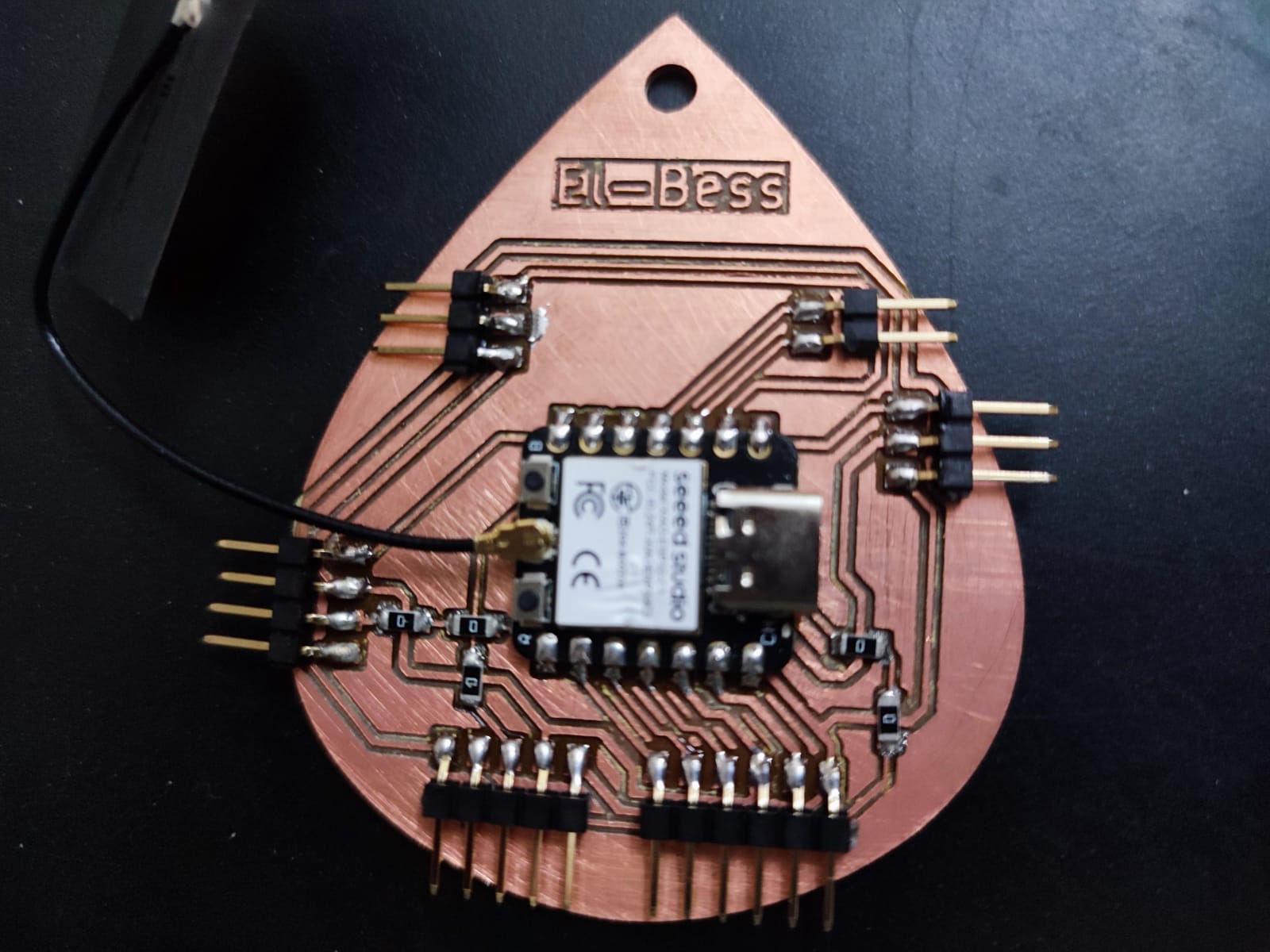
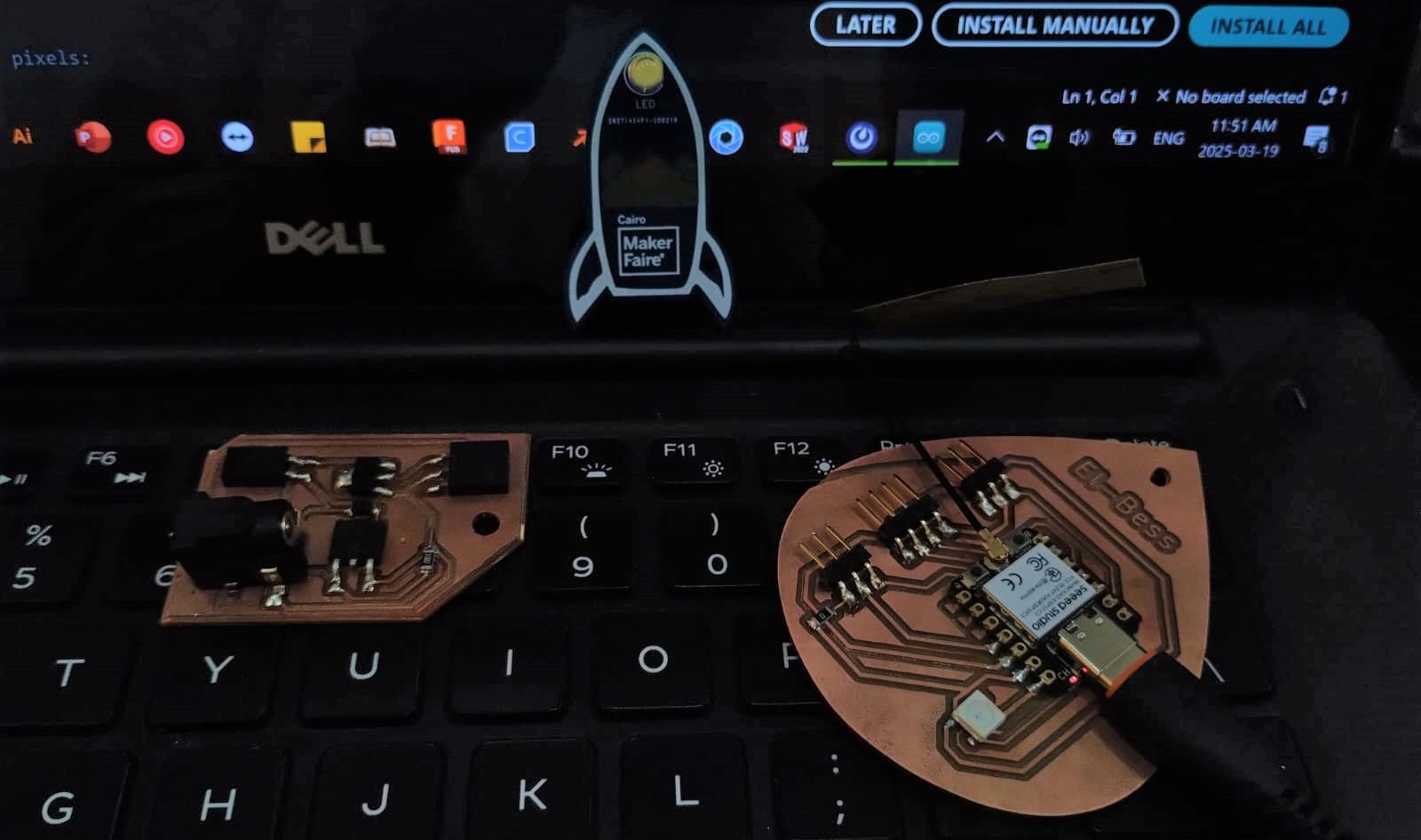
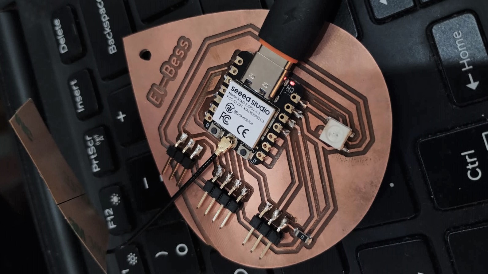
After some work in the next weeks I figured that I need to have a board with full pins out from the xiao to use it in different assignments. So I made this version 2 which I think I'll upgrade it to a final version for the final project soon.
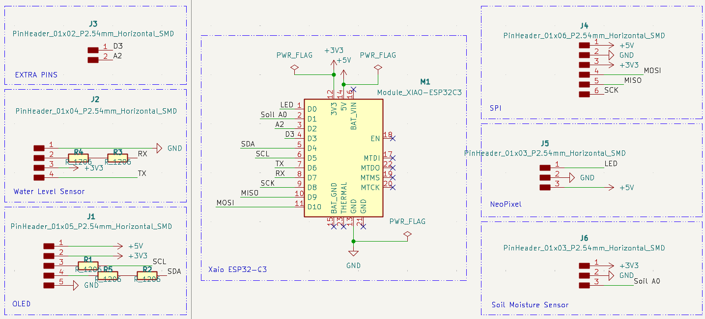
1- I updated the schematic to add more pins out for different components and added more power pins.
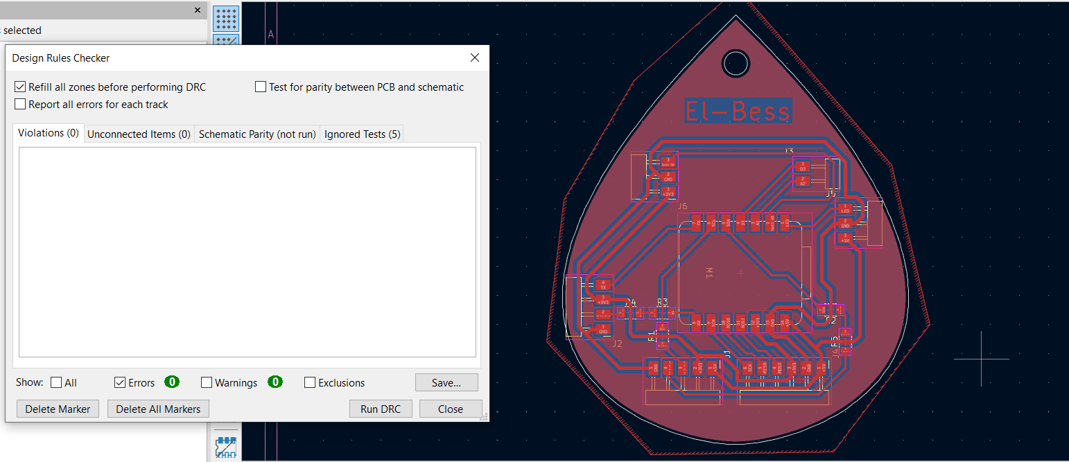
2- I updated the PCB and needed to add more 0 ohm resistors to help me routing.
3- After the same steps I described above, this was the look of the traces using the 0.4mm endmill.
4- Now you can see the outline and drill went well this time as I learned from my mistakes.
5- My colleague Amr suggested me I sand the PCB under running water to make it look nicer after the milling process.
6- Here I desoldered the components from the old PCB by using the desoldering pump and the heatgun.
7- I started soldering again and started with the smallest components using the solder paste and from inside of the PCB to the outside.